

Page 1

January 2006 350 Series Electrohydraulic Actuators
350 Series Electrohydraulic Actuators
(Obsolete Product)
Obsolete products may not be manufactured again in
any Fisher location under any conditions.
Recommended spare parts availability is guaranteed for
10 years after the last production on manufactured trim
replacement parts and 5 years of best effort on die cast
parts, elastomers, buyout
components, and electronic components. Postsale documents (such as instruction manuals)
will be available on CD Rom and the Fishweb.
Pre-sale documents (such as bulletins) for
obsolete are not included on the Fishweb or CDROM.
Fisher is a mark owned by Fisher Controls International LLC, a member of the Emerson Process Management business division of Emerson
Electric Co. The Emerson logo is a trademark and service mark of Emerson Electric Co. All other marks are the property of their respective owners.
The contents of this publication are presented for informational purposes only, and while every effort has been made to ensure their accuracy, they are
not to be construed as warranties or guarantees, express or implied, regarding the products or services described herein or their use or applicability.
We reserve the right to modify or improve the designs or specifications of such products at any time without notice.
Fisher does not assume responsibility for the selection, use or maintenance of any product. Responsibility for proper selection, use and
maintenance of any Fisher product remains solely with the purchaser and end-user.
Emerson Process Management
Fisher
Marshalltown, Iowa 50158 USA
Cernay 68700 France
Sao Paulo 05424 Brazil
Singapore 128461
www.Fisher.com
Fisher Controls International LLC 2004; All Rights Reserved Printed in USA
Page 2

Instruction Manual
Form 1387
June 2002
350 Series Electrohydraulic Actuators
Contents
Introduction 2. . . . . . . . . . . . . . . . . . . . . . . . . . . . .
Scope of Manual 2. . . . . . . . . . . . . . . . . . . . . . . . . . .
Description 2. . . . . . . . . . . . . . . . . . . . . . . . . . . . . . . .
Type Number Description 2. . . . . . . . . . . . . . . . . . .
Specifications 2. . . . . . . . . . . . . . . . . . . . . . . . . . .
Installation 6. . . . . . . . . . . . . . . . . . . . . . . . . . . . . . .
Valve Body and Actuator 6. . . . . . . . . . . . . . . . . . . .
Hydraulic Fluid 6. . . . . . . . . . . . . . . . . . . . . . . . . . . .
Electrical Connections 7. . . . . . . . . . . . . . . . . . . . . .
Power 7. . . . . . . . . . . . . . . . . . . . . . . . . . . . . . . . . . .
Input Signal 7. . . . . . . . . . . . . . . . . . . . . . . . . . . . . .
Seal Drain-Off Connection 7. . . . . . . . . . . . . . . . . .
Startup 7. . . . . . . . . . . . . . . . . . . . . . . . . . . . . . . . . . .
Adjustments 7. . . . . . . . . . . . . . . . . . . . . . . . . . . . .
Zero/Span Calibration 7. . . . . . . . . . . . . . . . . . . . . .
Bypass Valve and Handwheel
Operation
Bypass Valve 8. . . . . . . . . . . . . . . . . . . . . . . . . . . . .
Bolt-On Handwheels 8. . . . . . . . . . . . . . . . . . . . . . .
Integrally Mounted Gear-Type Handwheels 9. . .
Speed Control Valve 9. . . . . . . . . . . . . . . . . . . .
Changing Actuator Action 10. . . . . . . . . . . .
Split-Range Operation 11. . . . . . . . . . . . . . . . .
Principle of Operation 11. . . . . . . . . . . . . . . . .
Lock in Last Position 11. . . . . . . . . . . . . . . . . . . . . .
Fault-Correction Guide 11. . . . . . . . . . . . . . . .
Maintenance 13. . . . . . . . . . . . . . . . . . . . . . . . . . . .
Removing Casing Plate Assembly 13. . . . . . . . . .
Cleaning Force Motor 14. . . . . . . . . . . . . . . . . . . . .
Cleaning Primary Restrictions 14. . . . . . . . . . . . . .
Checking and Adjusting Pump Pressure 14. . . . .
Adjusting Nozzles 15. . . . . . . . . . . . . . . . . . . . . . . . .
Low-Pressure Nozzles 15. . . . . . . . . . . . . . . . . . .
High-Pressure Nozzles 16. . . . . . . . . . . . . . . . . . .
Replacing Oil Seals 16. . . . . . . . . . . . . . . . . . . . . . .
Adaptor Plug O-Rings 16. . . . . . . . . . . . . . . . . . . .
Upper Piston Rod Seal and Piston Seals 16. . .
Lower Piston Rod Seal 17. . . . . . . . . . . . . . . . . . .
Handwheel Maintenance 17. . . . . . . . . . . . . . . . . . .
Bolt-On Handwheels 17. . . . . . . . . . . . . . . . . . . . .
Integrally Mounted Gear-Type Handwheels 18.
8. . . . . . . . . . . . . . . . . . . . . . . . . . . . . . . .
W2286/IL
Figure 1. Type 350 Electrohydraulic Actuator with
Bolt-on Handwheel on Design ED Valve
Mounting Actuator and Adjusting
Stem Connection
Type 350 18. . . . . . . . . . . . . . . . . . . . . . . . . . . . . . . .
Type 354 Actuator Mounting 19. . . . . . . . . . . . . . .
Type 354 Valve Travel Adjustment 20. . . . . . . . . .
Changing Type 354 Actuator Mounting 21. . . . . .
Parts Ordering 21. . . . . . . . . . . . . . . . . . . . . . . . . .
Parts Kits 22. . . . . . . . . . . . . . . . . . . . . . . . . . . . . . .
Parts List 22. . . . . . . . . . . . . . . . . . . . . . . . . . . . . . . .
Actuator 22. . . . . . . . . . . . . . . . . . . . . . . . . . . . . . . . .
72 mm (2-13/16 Inch) Yoke Boss
Bolt-On Handwheel 26. . . . . . . . . . . . . . . . . . . . .
90 mm (3-9/16 Inch) Yoke Boss
Bolt-On Handwheel 30. . . . . . . . . . . . . . . . . . . . .
127 mm (5 Inch) Yoke Boss
Integral Handwheel 30. . . . . . . . . . . . . . . . . . . . .
90 mm (3-9/16 Inch) Yoke Boss
Integral Handwheel 30. . . . . . . . . . . . . . . . . . . . .
350 Actuator
18. . . . . . . . . . . . . . . . . . . . . .
www.Fisher.com
D100286X012
Page 3

350 Actuator
Instruction Manual
Form 1387
June 2002
Introduction
Scope of Manual
This instruction manual includes installation,
operation, maintenance, and parts ordering
information for Type 350 (figure 1) and 354
electrohydraulic actuators with and without optional
cylinder bypass valve and speed control valve.
Coverage of handwheels for Type 350 actuators is
also included. Refer to separate manuals for
instructions covering the control valve and
accessories.
No person may install, operate, or maintain a 350
Series actuator without first (1) being fully trained
and qualified in valve, actuator, and accessory
installation, operation, and maintenance, and (2)
carefully reading and understanding the contents of
this manual. If you have any questions about these
instructions, contact your Fisher sales office before
proceeding.
Description
The 350 Series electrohydraulic actuators are
designed to operate sliding-stem and rotary-shaft
control valves from standard electronic input signals
and electric power supplies. These actuators contain
Table 1. Specifications
all the elements necessary for control valve
operation in electronic control systems. The motor,
pump, transducer, and positioner are included in the
actuator casing.
For hazardous area applications, the actuator must
be equipped with an explosion-proof motor and an
intrinsically safe control circuit. Separate use of
either an explosion proof motor or an intrinsically
safe control circuit results in an actuator with no
hazardous area rating. Refer to the motor nameplate
and actuator nameplate for additional information.
Type Number Description
Type 350—Electrohydraulic control valve actuator
with threaded stem connection for use with
sliding-stem control valves.
Type 354—Electrohydraulic control valve actuator
with splined valve shaft connection for use with
rotary-shaft control valves.
Specifications
Specifications for 350 Series actuators are shown in
table 1. Some specifications may also be found on
the actuator nameplate.
Input Signals
See table 2
Internal Resistance of Transducer Force Motor
See table 2
Power Supply Required
See table 3
Actuator Sizes
Type 350: See table 4
Type 354:
J Size 60 for 25.4, 31.8, 38.1, 44.5 or 50.8 mm
(1, 1-1/4, 1-1/2, 1-3/4 or 2 inch) valve shaft spline
(1)
Action
Actuators with standard control circuits are fieldreversible between
J direct (increasing input signal extends actuator
piston rod) and
J reverse (increasing input signal retracts
actuator piston rod).
Actuators with intrinsically safe control circuits are
not field reversible; either a direct- or
reverse-acting coil is required.
Maximum Usable Output Thrust and Torque
diameter or
J Size 80 for 63.5 mm (2-1/2 inch) valve shaft
spline diameter
1. This term is defined in ISA S51.1.
2. Stroking speed with actuator operating a valve under no load.
3. Do not exceed the thrust and torque limits in this manual.
4. The temperature limits in this manual and in any applicable standard or code limitation should not be exceeded.
Type 350: See table 5
Type 354: See table 6
(3)
2
Page 4

Instruction Manual
Form 1387
June 2002
350 Actuator
Table 1. Specifications (continued)
Bench Stroking Speed
J 8.6 mm/second (0.37 inches/second) for 8900
N (2000 pounds) output thrust or 318 NSm
(2812 lbfSin) output torque and
J 3.8 mm/second (0.15 inches/second) for 22200
N (5000 pounds) output thrust or 794 NSm
(7031 lbfSin) output torque
Maximum Actuator Travel
Type 350: See table 4
Type 354: 90 degrees
Pump Type
Positive-displacement, gear-type pump with relief
valves.
Hydraulic Fluid Requirements
10.4 liters (11 quarts) of Type A automotive
automatic transmission fluid. If the actuator is
used in ambient temperatures below –4°C (25°F),
use an aircraft-type hydraulic fluid that conforms
to MIL-H-5606A specifications.
Operative Temperature
Weather-Proof Motor: –40 to 40°C (–40 to
104°F)
Explosion-Proof Motor: –25 to 40°C
(–13 to 104°F)
Performance
Hysteresis
(1)
: 0.50 percent of span
Load Sensitivity: Stem position change 0.3 to
1.0 percent of total travel per 488 Newton (100
pound) change in load
Terminal-Based Linearity
travel
Dead Band
(1)
: Less than 0.5 percent of total
travel
Frequency Response
frequency response curves
1. This term is defined in ISA S51.1.
2. Stroking speed with actuator operating a valve under no load.
3. Do not exceed the thrust and torque limits in this manual.
4. The temperature limits in this manual and in any applicable standard or code limitation should not be exceeded.
(2)
(1, 4)
(1)
: ±2 percent of total
(1)
: See figure 3 for typical
Adjustments
Zero and span adjustments located under cover
(figure 2)
Hazardous Area Classification
Actuators with intrinsically safe actuator control
circuits are available. Intrinsically safe control
circuits are indicated by the presence of a special
actuator nameplate and require an
explosion-proof motor. Refer to the special
actuator nameplate for information concerning
use of the actuator in hazardous locations. The
motor nameplate must also specify an
explosion-proof approval.
Motor Type
See table 3. Motor type designations refer to the
motor only; not to the entire actuator.
Connections
Power: 1/2-inch NPT female conduit connection
on motor
Input Signal: 1/2-inch NPT female conduit
connection on side of casing
Seal Drain Off: 1/4-inch NPT female connection
with vent assembly on top of yoke. This
connection is furnished only on 72 mm (2-13/16
inch) and
90 mm (3-9/16 inch) yoke boss sizes of the Type
350 actuators
Approximate Weight
Type 350 without Handwheels
72 mm (2-13/16 inch) Yoke Boss: 49 kg
(110 pounds)
90 mm (3-9/16 inch) Yoke Boss: 64 kg
(142 pounds)
127 mm (5-inch) Yoke Boss: 91 kg (200 pounds)
Type 354
Size 60: 86 kg (194 pounds)
Size 80: 123 kg (275 pounds)
3
Page 5

350 Actuator
TRAVEL
ADJUSTMENT
SCALE
BIAS
SPRING
ZERO
ADJUSTMENT
SPAN
ADJUSTMENT
W5568-1/IL
CASING
PLATE
ASSEMBLY
FEEDBACK
SPRING
Figure 2. Adjustments (Actuator is Shown with Cover Removed)
Instruction Manual
Form 1387
June 2002
Table 2. Input Signals, Internal Resistance, and Coil Part Numbers
CONTROL
CIRCUIT
ACTION
TYPE
Standard
Intrinsically
safe
1. Action must not be reserved. See the changing action section of this manual.
Either Field
Reversible
Reversible
Direct
Reverse
INPUT
SIGNAL,
mA dc
1-5 2200 2H2936000A2 1H309037022 1H308937022 1H681124092 1H681424092 1F546828992
4-20,
4-12,
or 12-20
10-50 380 2H2935000A2 1H440337022 1H440237022 1H681124092 1H681324092 1F546828992
(1)
4-20 160 23A1732X012 1H309037022 1H308937022 1H681124092 1H681324092 1F546828992
(1)
4-20 160 23A1733X012 1H309037022 1H308937022 1H681124092 1H681324092 1F546828992
INTERNAL
RESISTANCE,
OHMS
260 2J5228000A2 1H309037022 1H308937022 1H681124092 1H681224092 1P4252X0012
Key 37*
Key 37*
Coil
Assembly
Table 3. Motor Types and Corresponding Power Supplies Required
Weather-Proof Motor Explosion-Proof Motor
Electrical
Classification
of Motor
Type
Horsepower
Power
Supply
Starting Cur-
rent (Amps)
Running Cur-
rent (Amps)
Speed
1. Explosion-proof classification pertains to the motor only, not the entire actuator.
Totally Enclosed; Continuous Service—Intrinsically safe control
circuit not available with this motor
Capacitor Start, Induction Run Capacitor or Repulsion Start, Induction Run, Fan Cooled
1/3 1/3
115/230 ±10% Vac, Single
Phase, 60 Hz
31 Max @ 115 Vac
15.5 Max @ 230 Vac
7.2 @ 115 Vac
3.6 @ 230 Vac
1725 RPM 1425/1725 RPM 1725 RPM 1425/1725 rpm
220/440 ±10% Vac, Three
Phase, 50/60 Hz
8 Max @ 220 Vac
4 Max @ 440 Vac
1.8 @ 220 Vac
0.9 @ 440 Vac
PART NUMBERS
Key 81, Stainless Steel Key 124, Steel
Bias
Spring
Feedback
Spring
Explosion-proof (see motor nameplate for specific rating). Also check
for special actuator nameplate to determine if actuator
has intrinsically safe control circuit. Unless the control circuit is
intrinsically safe and the motor is explosion proof, actuator cannot be
used in hazardous atmospheres.
115/230 ±10% Vac, Single
Phase, 60 Hz
31 Max @ 115 Vac
15.5 Max @ 230 Vac
7.2 @ 115 Vac
3.6 @ 230 Vac
Weight Weight
220/440 ±10% Vac, Three Phase,
50/60 Hz
8 Max @ 220 Vac
4 Max @ 440 Vac
1.8 @ 220 Vac
0.9 @ 440 Vac
Key 166
Key 166
Machine
Screw, Steel
(1)
4
*Recommended spare parts
Page 6

Instruction Manual
Form 1387
June 2002
13 mm
(1/2 INCH)
TRAVEL
29 mm
(1-1/8 IN)
TRAVEL
76 mm
(3- INCH)
TRAVEL
13 mm
(1/2 INCH)
TRAVEL
29 mm
(1-1/8 IN)
TRAVEL
76 mm
(3- INCH)
TRAVEL
350 Actuator
mm
(INCH)
13A6501-A
A1617-2/IL
NOTE:
FOR 71mm (2-13/16 INCH) YOKE BOSS SIZE TYPE 350 ACTUATOR WITH 1 TO 5 mA DC INPUT SIGNAL (5% INPUT
AMPLITUDE) AND 8896 N (2000 POUNDS) OUTPUT THRUST
Figure 3. Typical Frequency Response Curves
Table 4. Maximum Actuator Travel for Type 350
Types
350 without handwheel
350 with handwheel
1. An actuator with this yoke boss size uses a 19.1 mm (3/4-inch) stem. When this size actuator stem is used, the valve stem must be less than the standard length.
Table 5. Usable Thrust Output of Type 350 Actuators at Maximum Travel
Actuator Type
Yoke Boss Size, mm (Inch)
Travel, mm (Inch)
Gross Cylinder
Output Thrust, N (Lb)
Usable Output
Thrust, N (Lb)
1. Thrusts given are the thrusts available for operation of control valves. Under some conditions, such as with the valve plug stalled, higher thrusts can be developed. The control valve
stem must be capable of withstanding this higher thrust.
YOKE BOSS SIZE TRAVEL
mm Inch mm Inch
72
90 or 127
72
90
127
2-13/16
3-9/16
2-13/16
3-9/16
5
(1)
or 5
(1)
38
76
38
64
76
(1)
350
(w/ or w/o handwheel)
72
(2-13/16)
38
(1-1/2)
8896
(2000)
8896
(2000)
90 or 127
(3-9/16 or 5)
64 or 76
(2-1/2 or 3)
8896 or 22240
(2000 or 5000)
8996 or 22240
(2000 or 5000)
1-1/2
3
1-1/2
2-1/2
3
5
Page 7

350 Actuator
Table 6. Usable Torque Output of Type 354
Size 60 and 80 Actuators at Maximum Travel
Gross Cylinder
Output Thrust, N (Lb)
Valve Disk or Ball
Rotation, Degrees
Usable Torque Output,
NSm (LbfSin)
1. Do not exceed torque capabilities of the valve shaft.
Table 7. Side-Mounted Handwheels for Type 350 Actuators
YOKE BOSS
SIZE, mm
(INCHES)
72
(2-13/16)
90
(3-9/16)
127
(5)
1. Can also open or close valve in emergency without inserting engaging pin.
HANDWHEEL TYPE
Non-Declutchable Open or Close Up or Down Neutral Position
Bolt-on
Bolt-on
Integrally Mounted Open, Close, or Throttle
Declutchable Open, Close, or Throttle –––
Non-Declutchable Open or Close Up or Down Neutral Position 51 (2)
Declutchable Open, Close, or Throttle –––
Positioning of Valve
OPERATION
Use As
Travel
(1)
Up or Down
8800
(2000)
0-90 0-90
318
(2812)
Action Required
Stop
Unrestricted Travel
Neutral Position &
Disengage Pin
Neutral Position &
Disengage Pin
Neutral Position &
Disengage Pin
22000
(5000)
794
(7031)
for
Instruction Manual
Form 1387
June 2002
(1)
(1)
MAXIMUM ACTUATOR
TRAVEL WITH
HANDWHEEL, mm (INCHES)
38 (1-1/2)
64 (2-1/2)
76 (3)
Installation
WARNING
Always wear protective gloves,
clothing, and eyewear when
performing any installation operations
to avoid personal injury.
Check with your process or safety
engineer for any additional measures
that must be taken to protect against
process media.
Key numbers referenced in the following procedures
are shown in figure 7 except where indicated.
These actuators are normally shipped as part of a
control valve assembly. That is, the actuator will be
mounted on a control valve body and the connection
between the actuator piston rod and valve will be
assembled when the unit is received. Complete
instructions for the valve body are provided in a
separate manual.
sections, and then complete the Actuator Mounting
and Adjusting Stem Connection procedures.
Valve Body and Actuator
Install the valve body in the pipeline by following
instructions in the appropriate valve body instruction
manual. (Some rotary valves must be out of the
pipeline in order to determine the closed position for
actuator adjustment. These valves should remain
out of the line until the actuator has been mounted
and adjusted.)
For proper operation, the actuator must be installed
in a vertical position above the control valve body.
Hydraulic Fluid
Clean the casing plate (key 19) to be certain no dust
or other foreign material enters the casing (key 5).
Unscrew the vent assembly (key 92). When filling
the reservoir, use a funnel having a fine-screen
strainer to prevent solid impurities from entering the
casing.
If the actuator has been shipped separately for
mounting on a control valve body or if the control
valve body and actuator have been separated for
maintenance, attach the actuator to the valve by
following the appropriate steps in the mounting
actuator section. Complete the remaining installation
6
Use approximately 10.4 liters (11 quarts) of type A
automotive-type automatic transmission fluid. If the
motor and pump are to be started at ambient
temperatures below –4°C (25°F), use an
aircraft-type hydraulic fluid (conforming to
MIL-H-5606A specifications).
Page 8

Instruction Manual
Form 1387
June 2002
350 Actuator
Fill the reservoir to the centerline of the sight gauge
(key 112). Replace the vent assembly after filling.
Electrical Connections
Power
Make power connections through the conduit
connection on the motor. Refer to the wiring tag
attached to the motor for instructions.
CAUTION
Reversed motor rotation may damage
the pump. Correct rotation is
counterclockwise when viewed from
the motor output shaft (clockwise
when viewed from the fan end of the
motor). Motor rotation is also indicated
by an arrow on the motor mounting
bracket.
Input Signal
Note
For intrinsically safe installations, refer
to the special nameplate and the
instructions provided by the barrier
manufacturer for proper wiring and
instructions. Do not attempt to reverse
the action of an actuator with an
intrinsically safe control circuit—refer
to the warning in the Changing
Actuator Action section.
Remove machine screws and junction box cover
(keys 86 and 85) from the bottom of the actuator
casing.
Insert the signal wires through the 1/2-inch NPT
female connection in the side of the actuator.
Provide a suitable conduit connector.
For direct-acting actuators (increasing input signal
extends actuator piston rod), connect the positive
input signal wire to the positive (+) terminal and the
negative wire to the negative (–) terminal. For
reverse-acting actuators (increasing input signal
retracts actuator piston rod) with standard control
circuits, reverse the input wires on the terminals.
Seal Drain-Off Connection
Some variations of these actuators are equipped
with a double piston rod seal. If so equipped, the
actuator is furnished with a vent (key 113, figure 8)
installed in the yoke. This vent allows draining of oil
that leaks past the high-pressure piston rod seal
(key 12). If the drained oil will create a fire hazard,
remove the vent and install a remote drain pipe to
carry leakage to a safe location.
Startup
Key numbers referenced in this procedure are
shown in figure 7. Follow this procedure to ensure
that the actuator is operational before putting it into
service. Remove cover screws and cover (keys 88
and 87) from the top of the actuator.
Note
The machine screw (key 123) and two
locknuts are installed in the force
motor to protect the force motor
during shipping. The force motor will
not function until this screw is
removed. Do not replace the screw
unless the actuator is to be moved.
Start motor and allow pressure lines to fill. Loosen,
but do not remove, the pipe plug (key 114) on top of
the piston rod. Allow air bubbles to bleed through the
pipe plug connection until the bubbles cease to
appear. Tighten pipe plug. Adjust per the following
section.
Adjustments
Before adjusting the zero and span, adjust the travel
adjustment scale (see figure 2) to the travel required.
Be certain the stem connector has been properly
installed and adjusted per the Mounting Actuator and
Adjusting Stem Connection section. If the actuator is
equipped with an optional handwheel, be certain the
handwheel engaging pin has been pulled out (if the
handwheel is equipped with an engaging pin) and
that the handwheel pointer is at the neutral position
before proceeding.
Zero/Span Calibration (see figure 2)
With power connected to the motor, adjust the input
signal to the signal (direct or reverse acting) which
should correspond to the full up position of the piston
7
Page 9

350 Actuator
Instruction Manual
Form 1387
June 2002
rod assembly. Rotate the zero (bias spring)
adjustment screw until the piston rod just begins to
move down. Change the input signal to the opposite
end of the input signal range and check the position
of the piston rod assembly. If the rod has moved less
than full travel, it indicates that the feedback spring
has too much tension and that the span (feedback
spring) adjustment screw is screwed into the spring
too far. If the rod has moved full travel, start moving
the input signal in the opposite direction to see
where the piston rod assembly starts to move. This
indicates if there is enough spring screwed onto the
span adjustment. After each adjustment of the span
(feedback spring) adjustment screw, the zero (bias
spring) adjustment screw must be adjusted for the
starting point (full up).
Bypass Valve and Handwheel Operation
Bypass Valve
Before using a handwheel, open the bypass valve
(key 76, figure 7) so that fluid pressure will be
equalized on either side of the actuator piston.
Failure to equalize the pressures may make
handwheel operation difficult or impossible.
Note
If the actuator is equipped with
optional lock valves, the bypass must
be opened to allow handwheel
operation even if the motor has been
turned off.
To open the bypass valve, rotate the bypass valve
stem (key 77, figure 10), located on the side of the
actuator, counterclockwise. This rotation direction is
indicated by an arrow on the bypass plate (key 79,
figure 10). Rotate the stem only enough to open the
valve (2 to 4 turns). Further rotation might damage
the bypass plate (key 79, figure 10).
Bolt-On Handwheels
Bolt-on handwheels (see figure 13) are available in
either of two types, non-declutchable and
declutchable. The non-declutchable type is shown in
figure 13. With this type, there is no declutching
mechanism, but the design of the handwheel nut
allows unrestricted actuator travel when the
handwheel is positioned so that the pointer (key 160,
figure 13) is at the neutral position. The handwheel
can be used to open or close the valve if used with a
Type 350 actuator (see table 7).
To operate the non-declutchable handwheel,
open the bypass valve and rotate the handwheel
clockwise to close or counterclockwise to open the
valve. The non-declutchable handwheel can also be
used as a travel stop to limit either full opening or
closing of the valve. With the handwheel pointer at
the neutral position, travel is not restricted. As the
pointer is moved from the neutral position, the
handwheel mechanism will restrict travel in an
increasing amount. Moving the pointer from the
neutral position with clockwise handwheel rotation
will restrict opening of the valve (counterclockwise
rotation will restrict closing of the valve). The
handwheel cannot be used to restrict opening and
closing at the same time.
The declutchable bolt-on handwheel is similar to the
handwheel shown in figure 13 except that the lever
pin (key 153, figure 13) is replaced by a removable
engaging pin (not shown). Unrestricted actuator
travel is possible when the engaging pin is pulled out
(engaging pin is retained by a cotter pin) and the
handwheel is positioned so that the pointer (key 160,
figure 13) is at the neutral position. The declutchable
handwheel can be used to open, close, or throttle
the valve regardless of the actuator type.
To operate the declutchable handwheel, open the
bypass valve. Rotate the handwheel to align the
engaging pin holes in the levers (key 146, figure 13)
with the hole in the handwheel body (key 142, figure
13). Insert the engaging pin. Rotate the handwheel
clockwise to close or counterclockwise to open the
valve. Install the cotter pin to retain the engaging pin.
The declutchable handwheel cannot be used as a
travel stop.
Handwheels for use with the Type 354 actuator are
covered in separate manuals. Refer to the Type
1076 handwheel or other handwheel instruction
manual as appropriate.
8
If the actuator is moved from a valve having
push-down-to-close action to one having
push-down-to-open action or vice versa, a new
handwheel nut and screw must be installed to retain
counterclockwise-to-open handwheel action. Follow
Page 10

Instruction Manual
Form 1387
June 2002
350 Actuator
the handwheel disassembly instructions in the
Maintenance section to change the nut and screw.
Integrally Mounted Gear-Type Handwheels
Handwheels furnished on the 127 mm (5-inch) yoke
boss size Type 350 are integrally mounted types as
shown in figure 14. For the 127 mm (5-inch) yoke
boss size Type 350 actuator, unrestricted actuator
travel is possible when the engaging pin (key 159,
figure 14) is pulled out and the handwheel is
positioned so that the pointer (key 158, figure 14) is
at the neutral position. The handwheels can be used
to open, close, or throttle the valve.
To operate the handwheel on 127 mm (5-inch) yoke
boss size Type 350 actuators, open the bypass
valve. Rotate the handwheel to align the engaging
pin holes in the sleeve (key 170A, figure 14) with the
hole in the piston rod (key 170B, figure 14). Insert
the engaging pin. Rotate the handwheel clockwise to
close or counterclockwise to open the valve.
With the integrally mounted handwheel on Type 350
actuators, the valve can be opened or closed in an
emergency without inserting the engaging pin.
Rotate the handwheel until the sleeve (key 170A,
figure 14) contacts either the stem connector or
travel stop nut (keys 2 and 178, figure 14). Once the
sleeve contacts the connector or travel stop nut,
further movement of the sleeve will move the piston
rod to open or close the valve.
Either integrally mounted handwheel type can be
used as a travel stop to limit either full opening or
closing of the valve. With the handwheel pointer at
the neutral position (and the engaging pin pulled out
for Type 350 actuators), travel is not restricted. As
the pointer is moved from the neutral position, full
travel will be restricted in one direction when the
travel stop nut or stem connector (keys 178 and 2,
figure 14) contacts the sleeve (key 170A, figure 14).
Moving the pointer from the neutral position with
clockwise handwheel rotation will restrict opening of
the valve (counterclockwise rotation will restrict
closing of the valve). The handwheel cannot be used
to restrict opening and closing at the same time.
If the actuator is moved from a valve having
push-down-to-close action to one having
push-down-to-open action or vice versa, reassemble
internal parts as follows to retain
counterclockwise-to-open handwheel action.
Remove the retainers, handwheel, bearings, and
worm (keys 180, 182, 190, and 181; figure 14).
Re-install these parts in the gear case opening
opposite the opening from which the parts were
removed. Refer to the disassembly instructions in
the Maintenance section for assistance.
Table 8. 350 Series Feedback Spring Cutting Details
Coil MA Signal
2J5228000A2
2J5228000A2
2J5228000A2
2H2935000A2
2H2936000A2
23A1732X012
23A1733X012
1H3089-C
A3925/IL
4-20
4-12
12-20
10-50
1-5
4-20
4-20
Use
Feedback Spring
1H308937022
1H308937022
1H308937022
1H440237022
1H308937022
1H308937022
1H308937022
Cut Feedback
Spring to:
22-1/2 coils
Do not cut
Do not cut
26-1/2-30-1/2
coils
30-1/2 coils
22-1/2 coils
22-1/2 coils
Speed Control Valve
The optional speed control valve (see figure 12) can
be used to restrict stroking speed in either direction
of piston rod travel and can be reversed in the field
to reverse the direction in which stroking speed is
restricted. The speed control valve is located under
the cover (key 87, figure 7) and is installed in the
cylinder pressure line connected to the bottom of the
cylinder. When the valve is installed with the arrow
(see figure 12) pointing away from the cylinder, fluid
flows freely to the bottom of the cylinder. Stroking
speed to retract the piston rod is not restricted.
However, when the piston rod is being extended,
return fluid flow from the bottom of the cylinder is
restricted by the speed control valve. This restricts
stroking speed to extend the piston rod.
The amount of restriction can be adjusted by rotating
the control valve (key 220, figure 12) stem.
Clockwise rotation increases the amount of
restriction. If it is desired to restrict stroking speed in
the opposite direction, unscrew machine screws (key
222, figure 12) and remove the straps (key 221,
figure 12). Remove the speed control valve and
reverse it in the cylinder pressure line. Re-install
straps and machine screws. The arrow on the speed
control valve body indicates the direction of
adjustable fluid flow through the valve.
9
Page 11

350 Actuator
Instruction Manual
Form 1387
June 2002
BN2617-B
B0872-2/IL
Figure 4. Operational Schematic of Type 350 Actuator
Changing Actuator Action
WARNING
The action of a 350 Series actuator
with an intrinsically safe control circuit
must not be reversed in the field. The
reversed input signal may create a
spark capable of igniting a hazardous
atmosphere, resulting in personal
injury or property damage. (The
reversed input signal will not operate
the actuator.) A reverse-acting coil is
required for reverse action with an
intrinsically safe control circuit.
For actuators with standard control circuits, action
can be changed from direct to reverse or vice versa,
by reversing the positions of the input signal wires
on the terminal strip (key 90, figure 7).
For direct-acting actuators (increasing input signal
extends actuator piston rod), the positive input signal
wire is to be connected to the positive (+) terminal,
and the negative wire to the negative (–) terminal.
For reverse-acting actuators (increasing input signal
retracts actuator piston rod), the position of the input
wires are reversed on the terminals.
Readjust zero and span after changing action.
10
Page 12

Instruction Manual
Form 1387
June 2002
350 Actuator
Split-Range Operation
The coil used for the standard 4 to 20 milliamp input
signal can also be used for an equal 4 to 12 and 12
to 20 milliamp split. (Intrinsically safe control circuits
cannot be used for split ranges.). For split-range
operation with 1 to 5 milliamp input signal, coils
specifically designed for split-range operation must
be used.
If an input signal change requiring a new coil is
being made in the field, new bias spring, feedback
spring, and weights (key 81, figure 7; key 124, figure
11) may be required. Check table 2 to determine
which parts are required.
For some coils and ranges, replacement feedback
springs must be cut to length in the field. When
measuring and cutting a spring, count the number of
coils from the end of the spring that has the long,
straight end. Leave enough extra spring wire to form
the bend in the end of the spring. See table 8.
Zero and span adjustments are made in the same
sequence for both full-range and split-range
operation except that only a portion of the full input
signal is used for split-range operation. For example,
with an equal two-way split using the 4 to 20
milliamp input signal, one actuator will be adjusted to
begin travel at 4 milliamps and to reach full travel at
12 milliamps. The other actuator will be adjusted to
begin travel at 12 milliamps and to reach full travel at
20 milliamps.
Principle of Operation
This section describes operation of a direct-acting
actuator (increasing input signal extends actuator
piston rod.) The operation of a reverse-acting
actuator is similar except that increasing input signal
retracts the actuator piston rod. Refer to the
operational schematic drawing in figure 4. An
increase in the input signal applied to the coil causes
the coil to move toward the force motor, pivoting a
flapper closer to the nozzle at A and farther from the
nozzle at B in figure 4. This increases the pressure
in the bellows connected to nozzle A and reduces
the pressure in the bellows connected to nozzle B.
The unbalanced pressures in the bellows pivot a
flapper closer to nozzle D and farther from nozzle C.
The capping effect on nozzle D causes the operating
pressure piped to the cylinder top to build. The
unbalanced pressures acting on the piston cause the
piston and piston rod to move downward. Fluid
below the piston is exhausted through nozzle C.
As the piston rod moves downward, the taper of the
feedback cam allows the feedback lever to move to
the left, decreasing tension in the feedback spring.
Downward stem movement continues until tension in
the feedback spring balances the force created by
current in the force motor. When these forces are
equal, the flappers are in a steady-state condition
with the valve stem in the position dictated by the
input signal.
A decreasing input signal moves the coil in the
opposite direction, moving the piston rod upward.
Lock-in-Last Position
Optional shutoff valves lock the piston rod and valve
stem in position if electrical power or hydraulic
pressures fail. In operation, the valves are held open
by the force of the pressure from the top pump
section. If electrical power or hydraulic pressure
fails, the shutoff valve springs close the shutoff
valves, locking existing pressure on either side of the
piston and locking the piston rod in position. The
lock-in-last position option will limit stem movement
to 0.41 to 0.46 mm (0.016 to 0.018 inches) per hour
after system stabilization with a stem load of
approximately 1780 Newtons (400 pounds).
Fault-Correction Guide
Table 9 is intended as a guide for isolating and
correcting operating difficulties. Perform each check
in order and check the operation of the actuator after
each correction step. Key numbers referenced in this
guide are shown in figure 7 except where indicated.
11
Page 13

350 Actuator
Fault Possible Cause Check Correction
1. Sluggish piston rod movement
or no piston rod movement
Table 9. Fault-Correction Guide
Electrical system
a. Machine screw (key 123) not
removed
a. Remove cover (key 87) and
check to be sure screw has been
removed.
Instruction Manual
Form 1387
June 2002
a. Remove screw and two locknuts.
b. Reversed motor rotation
c. Input signal not reaching
actuator
d. Input signal not reaching coil
e. Coil shorted or dirty and does
not move with change in input
signal
Hydraulic system
a. Bypass valve not full closed
b. Pump relief valves improperly
adjusted
c. Nozzles improperly adjusted
d. Primary restrictions plugged
b. Check power connections on
motor and motor rotation arrow on
mounting bracket.
CAUTION
Improper rotation could
result in pump damage.
c. Check input signal wires at
terminal strip (key 90) to determine
if input signal is reaching actuator.
d. Check wires (keys 133, 128,
and 130) at terminal plug
(key 102), terminal strip (key 89,
figure 12), and at coil (key 37) to
determine if input signal is
reaching coil.
e. Check coil resistance with
ohmmeter (see table 2 for
approximate resistance of the
coils); inspect coil and magnet for
dirt.
a. Check bypass valve on side of
actuator.
b. Check per Checking and
Adjusting Pump Pressure section.
c. Check per Adjusting Nozzles
section.
d. –––
b. Change motor power connections
if necessary.
c. If instrument supplying input
signal is functioning, correct the
input signal wiring.
d. Replace wires or terminals if
necessary.
e. Replace coil assembly if shorted;
clean coil and magnet per Cleaning
Force Motor section.
a. Close bypass valve by rotating
bypass valve stem (key 77,
figure 14).
b. Adjust per Checking and
Adjusting Pump Pressure section.
c. Adjust per Adjusting Nozzles
section.
d. Clean per Cleaning Primary
Restrictions section.
e. Seals leaking
2. Unusual pump noises 2. Trapped air in suction side of
pump
CAUTION
Trapped air could damage
pump; shut off motor and
correct immediately.
3. Cycling operation 3. If all other elements in the
system are functionally correct,
problem may be extreme pipeline
vibration.
12
e. If pump is supplying fluid at
appropriate pressure and nozzles
are adjusted properly, seal may
require replacement.
2. Be certain filter (key 117) is
completely submerged in hydraulic
fluid; check all fittings to be sure all
are tight.
3. ––– 3. Re-position actuator at 90
e. Replace per Replacing Seals
section.
2. Adjust position of filter by
loosening connection on pipe nipple
(key 283, not shown) at the pump,
re-positioning filter, and tightening
connection. Tighten all loose fittings.
degrees to direction of pipeline
movement.
Page 14

Instruction Manual
Form 1387
June 2002
350 Actuator
Maintenance
WARNING
Avoid personal injury or property
damage from sudden release of
process pressure or bursting of parts.
Before performing any maintenance
operations:
D Always wear protective gloves,
clothing, and eyewear when
performing any maintenance
operations to avoid personal injury.
D Disconnect any operating lines
providing air pressure, electric power,
or a control signal to the actuator. Be
sure the actuator cannot suddenly
open or close the valve.
D Use bypass valves or completely
shut off the process to isolate the
valve from process pressure. Relieve
process pressure from both sides of
the valve. Drain the process media
from both sides of the valve.
D Vent the pneumatic actuator
loading pressure and relieve any
actuator spring precompression.
D Use lock-out procedures to be
sure that the above measures stay in
effect while you work on the
equipment.
D The valve packing box may
contain process fluids that are
pressurized, even when the valve has
been removed from the pipeline.
Process fluids may spray out under
pressure when removing the packing
hardware or packing rings, or when
loosening the packing box pipe plug.
D Check with your process or safety
engineer for any additional measures
that must be taken to protect against
process media.
Parts are subject to normal wear and must be
periodically inspected and replaced as necessary.
The frequency of inspection and replacement of
parts depends upon the severity of service
conditions. Establish a routine maintenance
schedule after the severity of service conditions is
known.
Hydraulic fluid must be checked periodically. Check
fluid level through the sight gauge (key 112, figure 7)
located on the side of the actuator. Fluid level should
reach the centerline of the sight gauge. The level
should be checked often when the actuator is first
installed. Once the rate of fluid usage is known,
establish a routine inspection schedule.
Before adding hydraulic fluid, clean the casing plate
(key 19, figure 7) to prevent foreign material from
entering the casing. Unscrew the vent assembly (key
92, figure 7) and add fluid through a funnel having a
fine-screen strainer. Hydraulic fluid should be
drained and replaced at least once a year. When
changing the fluid, also change the filter (key 117,
figure 7).
To change the filter, first remove the casing plate
assembly in accordance with the following section.
Then, unscrew the machine screw (key 120, figure
7), and remove the filter support and element (keys
119 and 117, figure 7). Install the new filter element
and secure with the filter support and machine
screw.
Removing Casing Plate Assembly
Internal parts, except the piston and cylinder, can be
removed as an assembly. This assembly can be
replaced with a stand-by assembly to allow normal
operation during maintenance. To remove the casing
plate assembly, proceed as follows. Key numbers
referenced in this procedure are shown in figure 7
except where indicated.
1. Clean the top surface of the casing plate (key 19)
to avoid getting dirt in the casing (key 5). Unscrew
and remove ten cap screws (key 20) from the casing
plate.
2. When lifting the casing plate assembly, rotate it
slightly back and forth to loosen the O-rings (key 23)
that are held in the adaptor plug (key 21). Use care
to avoid damaging the O-rings when lifting.
3. If it is not necessary to move the casing plate
assembly away from the actuator, cover the
feedback cam (key 17) with a piece of cardboard
and prop the casing plate assembly against the cam.
Rest the motor end of the assembly on the casing.
4. If the casing plate is to be moved away from the
actuator, disconnect the wire assembly (key 128)
from the terminal strip (key 89, figure 11) located on
the pilot block (key 57, figure 11).
5. Use reasonable care in handling the casing plate
assembly. Flexures (keys 50, 53, and 54; figure 11)
used to mount the flappers (keys 46, 48, and 67;
13
Page 15

350 Actuator
Instruction Manual
Form 1387
June 2002
figure 11) can be damaged if the assembly is
handled roughly.
6. Inspect the three O-rings (key 23) in the adaptor
plug (key 21); replace if necessary.
7. Before replacing the casing plate assembly, be
certain the wire assembly (key 128) is connected to
the terminal strip (key 89, figure 11). Carefully guide
the adaptor plug over the feedback cam and onto
the cylinder cap assembly (key 8).
Cleaning Force Motor
Key numbers referenced in this procedure are
shown in figure 7.
The force motor coil assembly (key 37) must be free
to move toward and away from the magnet (key 38)
in response to changes in the input signal.
Accumulation of dirt or other foreign material on the
coil or magnet can hinder coil movement and cause
faulty actuator operation. To clean the magnet and
coil, proceed as follows.
1. Unscrew the cover screws (key 88) and remove
the cover (key 87).
2. Disconnect wires (key 130) from the coil.
Unscrew and remove the machine screw (key 121).
3. Loosen the machine screw (key 25). Remove the
magnet and coil assemblies.
4. Remove dirt and other foreign material from the
coil and magnet by picking it off with cellophane
tape.
73, figure 11) may become partially clogged. This
will result in sluggish actuator operation. To clean
the restrictions, proceed as follows.
1. Remove the casing plate assembly and prop it
against the feedback cam as described in the
Removing Casing Plate Assembly section.
2. Unscrew the two restriction fittings (key 73, figure
11) from the amplifier base (key 72, figure 11).
3. Run a cleaning wire through the 0.64 mm
(0.025-inch) orifices in the fittings; then wash out the
openings.
4. If necessary, loosen the pipe nipple (key 283, not
shown) at the pump (key 196). Rotate the filter (key
117) into the hydraulic fluid.
5. Disconnect the high-pressure tubes (keys 104
and 105) from the amplifier assembly. Loosen the
high-pressure tube fittings at the pump. Rotate the
high-pressure tubes until the tube ends are
submerged in hydraulic fluid. Tighten the pump tube
fittings.
6. Be certain the casing plate assembly is solidly
propped on the casing. Start the motor to flush the
hydraulic amplifier. Let the motor run for
approximately 5 minutes.
7. If necessary, install new O-rings (key 74, figure
11) on restriction assemblies.
8. Re-install restriction assemblies into the amplifier
block. Tighten securely.
9. Re-connect and tighten high-pressure tube
fittings. Re-position the filter and tighten the filter
tube fitting.
CAUTION
Individual components of the coil and
magnet assemblies are not field
replaceable. Order a new coil or
magnet assembly if repair is
necessary.
5. After cleaning, reassemble in reverse order of the
above steps. Be certain the wires (key 130) have
enough slack to allow the coil to move in response to
changes in input signal.
Cleaning Primary Restrictions
Key numbers referenced in this procedure are
shown in figure 7 except where indicated.
Over a long period of time, especially under dirty
operating conditions, the primary restrictions (key
14
Checking and Adjusting Pump Pressure
Key numbers referenced in this procedure are
shown in figure 7 except where indicated.
1. Remove the casing plate assembly and prop it
against the feedback cam as described in the
Removing Casing Plate Assembly section.
2. Disconnect the high-pressure tubes (keys 104
and 105) from the amplifier assembly.
3. Connect two 50-bar (600 psig) pressure gauges
to the ends of the high-pressure tubes.
4. If necessary, loosen the connection on the pump
end of the pipe nipple (key 283, not shown) and
rotate the filter (key 117) under the hydraulic fluid.
5. Be certain the casing plate assembly is solidly
propped on the casing.
Page 16

Instruction Manual
Form 1387
June 2002
350 Actuator
CAUTION
When checking pressure, allow the
motor to run only an instant (just long
enough to bring the pressure
indication on the gauges to maximum),
or overheating and damage to the
motor may result.
Turn on the motor and read the pressure gauges.
6. Both gauges should indicate pressure between
34.5 and 36.2 bar (500 and 525 psig).
7. Each pump section has an adjustable relief valve
located on the side of the pump opposite the output
connections. Remove cap nuts covering the relief
valve adjustments. Use a screwdriver to adjust the
relief valves. Replace cap nuts immediately after
adjusting to prevent air from entering the system.
8. After adjusting, run the motor for an instant to
check output pressure. Re-adjust relief valves if
necessary.
9. When adjustments are complete, remove the 50
bar (600 psig) pressure gauges. Loosen high
pressure tube fittings at the pump and rotate the
tubes until the ends are submerged in hydraulic fluid.
Tighten high-pressure tube fittings at the pump.
10. Disconnect the low-pressure tube (key 103)
from the block (key 57, figure 11), and attach a 10
bar (75 or 100-psig) pressure gauge to it.
11. Be certain the casing plate assembly is solidly
propped on the casing.
CAUTION
When checking pressure, allow the
motor to run only an instant (just long
enough to bring the pressure
indication on the gauges to a
maximum), or overheating and damage
to the motor may result.
Turn on the motor and read the pressure gauge.
12. The gauge should indicate pressure between
3.4 and 4.1 bar (50 and 60 psig).
13. The low-pressure pump section has an
adjustable relief valve located on the side of the
pump opposite the output connection. Remove the
cap nut covering the relief valve adjustment. Use a
screwdriver to adjust the relief valve. Replace the
cap nut immediately after adjusting to prevent air
from entering the system.
14. After adjusting, run the motor for an instant to
re-check output pressure.
15. Re-adjust the relief valve if necessary.
16. When adjustment is complete, remove the
pressure gauge. Re-connect and tighten all tubing
connections. Return the filter to the normal position.
17. If no further maintenance is necessary, replace
the casing plate assembly on the casing.
Adjusting Nozzles
If the nozzles (keys 71 and 64, figure 11) require
adjustment or if the amplifier has been
disassembled, adjust as follows. Key numbers
referenced in this procedure are shown in figure 11
where indicated.
Remove the casing plate assembly and prop it
against the feedback cam as described in the
Removing Casing Plate Assembly section.
Low-Pressure Nozzles
1. Remove two machine screws and spray shield
(keys 122 and 127) from the amplifier base (key 72).
To adjust nozzles, it is necessary to attach a 5 bar
(60 psig) pressure gauge to each of the holes from
which the machine screws were removed.
Note
The machine screw holes are tapped
1/4-inch (28 UNF) and will not accept
pipe threads. Provide suitable
adaptors to convert from the machine
screw threads to the pressure gauge
threads.
In the following steps, the directions
right and left are given assuming that
the amplifier is being viewed as shown
in figure 11.
2. Loosen the locknut found on the right nozzle
located on the amplifier base (key 72). Adjust the
nozzle so that the right flapper (key 48) will act as a
stop and result in approximately 1.6 to 2.4 mm (1/16
to 3/32-inch) clearance between the coil assembly
(key 37, figure 7) and the outer pole piece (key 38B,
figure 7). The flapper should rest firmly on the nozzle
but should not bend.
3. Loosen the locknut (key 36) located on the left
nozzle (key 71).
15
Page 17

350 Actuator
Instruction Manual
Form 1387
June 2002
CAUTION
To avoid damage to the flappers and
flexures, move the beam (key 39) and
coil (key 37, figure 7) carefully.
4. With the beam (key 39) moved to the right, rotate
the left nozzle (key 71) until there is a clearance
between the nozzle and left flapper (key 46) of
approximately 0.10 mm (0.004 inches).
5. Disconnect the high-pressure tubes (keys 104
and 105, figure 7) from the amplifier assembly.
Loosen the connections on the pump end of the
tubes and rotate the tubes until the ends are
submerged in hydraulic fluid. Retighten the pump
connections. If necessary, loosen the pipe nipple
(key 283, not shown) connection on the pump and
rotate the filter (key 117, figure 7) until it is
submerged in hydraulic fluid.
6. Start the motor and observe the pressure gauges
in the amplifier. Each gauge should register
approximately 1.9 to 2.2 bar (28 to 32 psig) when the
beam (key 39) is moved to the center of beam travel.
7. If pressure is not 1.9 to 2.2 bar (28 to 32 psig) on
each gauge, rotate the left nozzle (key 71) only up or
down until the pressure is correct.
8. When the beam is moved manually through full
travel, each gauge should vary from approximately
1.0 bar (15 psig) to the pump supply pressure of
3.4 to 4.1 bar (50 to 60 psig).
9. When the adjustment is correct, remove the
pressure gauges and return the pressure lines and
filter to operational position. Replace the spray
shield and machine screws.
the terminal strip (key 89, figure 11). Completely
remove the casing plate assembly from the actuator.
Adaptor Plug O-Rings
Remove the three O-rings (key 23) from the adaptor
plug (key 21) and replace with new O-rings.
Upper Piston Rod Seal and Piston Seals
1. Remove the drain plug (key 111) and drain
hydraulic fluid from the casing (key 5).
2. Disconnect all tubing connections from the
cylinder cap assembly (key 8).
3. Using care to avoid scratching the cam surface,
unscrew the feedback cam (key 17) from the
feedback rod (key 16B). Install a new O-ring (key 18)
on the feedback cam.
4. Unscrew and remove the tie rod nuts (key 10).
Remove the cylinder cap (key 8D).
5. Remove the felt oil seal (key 8A) and install a
new seal. Remove the O-ring and backup ring
located between the guide bushing (key 8B) and
cylinder cap. When installing the new O-ring and
backup ring, be certain the backup ring is installed
adjacent to the cap (on the side of the O-ring
opposite the guide bushing). Be certain the O-ring is
not twisted.
6. Install a new O-ring (key 192) on the cylinder cap.
7. To replace the piston seal parts (keys 15 and
136), remove the cylinder (key 6) from the cylinder
base (key 7).
CAUTION
High-Pressure Nozzles
To adjust high-pressure nozzles (key 64), first be
certain the bellows beam (key 67) is at rest. Use
feeler gauges to measure the clearance between
each ball (key 66) and bellows bolt (key 68). Using
two 0.009 inch feeler gauges, loosen the locknut
(key 65) and rotate the nozzle(s) up or down for a
total of 4.6 mm (0.18 inch) clearance.
Replacing Oil Seals
Key numbers referenced in the following procedures
are shown in figure 7 except where indicated.
Remove the casing plate assembly per instructions
in the Removing Casing Plate Assembly section
above. Disconnect the wire assembly (key 128) from
16
Do not attempt to disassemble the
feedback rod (key 16B) or piston (key
16C) from the piston rod (key 16A).
The reassembly of these parts
involves special procedures and
sealant and is extremely difficult to
perform in the field. Order a new
piston rod assembly if replacement is
required.
8. Remove the O-ring and two backup rings (keys
15 and 136) from the piston. Replace with new parts,
making certain the O-ring is installed between the
two backup rings and is not twisted. Install the new
O-ring on the cylinder base (key 7).
9. If it is not necessary to replace the lower piston
rod seal (key 12), reassemble in the reverse order of
the procedure used to disassemble. Tighten the tie
Page 18

Instruction Manual
Form 1387
June 2002
350 Actuator
rod nuts (key 10) evenly to prevent binding the
piston.
Lower Piston Rod Seal
1. Remove the drain plug (key 111) and drain
hydraulic fluid from the casing (key 5) if this has not
already been done. For 122 mm (5-inch) yoke boss
size Type 350 actuators with handwheel, pull out the
engaging pin (key 159, figure 14).
2. Follow the appropriate procedure below:
a. For Type 350 actuators, remove the stem
connector assembly (key 2, figure 8) from piston
rod (key 16, figure 8).
b. For Type 354 actuators (figure 9), remove
the snap rings (key 202, 213, and 214). Loosen
the clevis locknut (key 201). Disconnect the clevis
(key 2) by first removing the snap ring and pin
that are in the clevis. Unscrew the clevis and
clevis locknut from the piston rod (key 16, figure
8). Remove the clevis boot (key 212).
3. Disconnect all wiring from casing (key 5).
4. Remove cap screws (key 4, figure 5). Remove
entire casing (key 5) from yoke (key 1, figure 8).
5. The hex portion of seal bushing (key 13) is now
exposed and can be used to unscrew the bushing
from casing.
6. Remove old O-ring and backup ring (keys 12 and
137) from bushing. When installing new O-ring and
backup ring, be certain the backup ring is on the side
of the O-ring facing the hex end of the bushing.
Install new O-ring facing the hex end of the bushing.
Install new O-ring (key 14) on threaded end of
bushing.
7. If the cylinder has been disassembled per the
previous section and it is desired to replace the
O-ring (key 11) between the cylinder base (key 7)
and casing (key 5), disconnect tubing from cylinder
base, remove base, and install new O-ring.
8. Reassemble in the reverse order of the
procedure used to disassemble. Tighten cylinder tie
rod nuts (key 10) evenly to avoid binding the piston.
Handwheel Maintenance
Refer to the separate Type 1076 handwheel
instruction manual for information of the Type 1076
handwheel for use with the Type 354 actuator.
Bolt-On Handwheels
Key numbers referenced in this procedure are
shown in figure 13 except where indicated.
Non-declutchable handwheels include a grease
fitting (key 169). Periodically, use this fitting to
lubricate with a good-quality general-purpose
grease. If it is necessary to disassemble the
handwheel assembly, use the following procedure.
1. Disconnect levers (key 146) from the stem
connector assembly.
2. To remove the handwheel assembly:
a. For 90 mm (2-13/16 inch) yoke boss size,
remove the handwheel-mounting cap screws and
U-bolt (key 166).
b. For 127 mm (3-9/16 inch) yoke boss size,
unscrew the hex nuts (keys 144 and 170) from
the U-bolts (keys 143 and 166).
3. Follow the appropriate procedure:
a. For declutchable handwheels, remove the
cotter pin from the engaging pin, and pull out the
engaging pin.
b. For non-declutchable handwheels, remove
the snap ring (key 154), and drive out the lever
pin (key 153).
4. To release the levers (key 146), unscrew and
remove two machine screws and nuts (keys 156 and
158).
5. Unscrew and remove the pointer screw (key 161)
and the pointer bolt that is located behind the pointer
(key 160).
6. Unscrew the nut (key 54) and remove the
handwheel (key 51). Be careful to avoid losing the
ball and spring (keys 55 and 56).
7. Loosen the set screw (key 168). Unscrew and
remove the bearing retainer (key 136). The bearing
will be removed with the retainer.
8. Pull out the screw assembly (key 145). The
operating nut (key 132) will be removed with the
screw assembly. Remove the bearing (key 152).
9. Before reassembling, pack the bearings with a
good-quality general-purpose grease. Apply
Lubriplate No. 130AA lubricant or equivalent to the
screw assembly threads, the ball, and the tips of the
guide bolts (key 167).
10. Reassemble following steps 1 through 8 of this
procedure, but in reverse order.
17
Page 19

350 Actuator
Instruction Manual
Form 1387
June 2002
Integrally Mounted Gear-Type Handwheels
Lubricate the handwheel mechanism periodically
with a good-quality general-purpose grease. On the
127 mm (5-inch) yoke boss size, a grease fitting (key
187, figure 14) is provided for this purpose. If you
need to disassemble the handwheel mechanism,
use the following procedure. Key numbers
referenced in this procedure are shown in figure 14
except where indicated.
1. Remove the stem connector (key 2) and pointer
(key 158) from the sleeve. For 127 mm (5-inch) yoke
boss size, be certain the engaging pin (key 159,
figure 14) is removed from the sleeve and piston rod.
2. Remove the drain plug (key 111, figure 7), and
drain the casing.
3. Remove the cap screws (key 199, figure 14). Lift
the entire casing and attached adaptor and piston
rod off the yoke.
4. Rotate the handwheel until the sleeve (key 170A,
figure 14), is free of the worm gear (key 174).
Remove the sleeve.
5. Unscrew cap screws (key 176, figure 14).
Remove the gear case and attached parts. Remove
the retainer (key 175, figure 14). Remove the worm
gear (key 174, figure 14) and two bearings (key 173,
figure 14).
6. To remove the worm shaft (key 181) and
bearings (key 190):
a. Loosen the set screws (key 186) in the gear
case and, for 127 mm (5-inch) yoke boss size, in
the handwheel cap (key 185).
b. Unscrew the handwheel cap or hex nut (key
185) and remove the handwheel. Be careful to
avoid losing the ball and spring (keys 188 and
189).
c. Unscrew the worm shaft retainers (keys 179
and 180). Remove the worm shaft (key 181) and
bearings (key 190).
7. Before reassembling, pack all bearings with a
good-quality, general-purpose grease. Apply
Lubriplate No. 130A lubricant or equivalent to the
surface of the sleeve, worm shaft, worm gear, and
ball.
8. Reassemble following steps 1 through 7 of this
procedure, but in reverse order. If the handwheel
was disassembled to reverse the direction of rotation
required to open the valve (this would be required if
the actuator were being taken off a valve with
push-down-to-open action and re-installed on a
valve with push-down-to-close action or vice versa),
install the worm shaft (key 181) and retainers (keys
179 and 180) into the gear case hole opposite the
hole from which these parts were removed. Also, for
127 mm (5-inch) yoke boss Type 350 actuators,
install the gear case rotated 180 degrees from
original position.
9. When reassembling, adjust the bearings as
follows. Tighten the set screws (key 171, figure 14)
to eliminate free play in the bearings. Overtightening
the set screws will make handwheel operation
difficult. Lock the set screws in place with hex nuts
(key 191, figure 14).
Mounting Actuator and Adjusting Stem Connection
Type 350
1. Mount the actuator on the valve; secure with the
valve yoke locknut [eight cap screws and nuts for
127 mm (5 inch) yoke boss size].
2. Remove the stem connector assembly (key 2,
figure 8). Thread the stem locknuts (key 198,
figure 14) all the way onto the valve plug stem
thread. If the actuator is equipped with a torque arm
(key 100, figure 8), place it on the locknuts.
3. Position the valve plug as follows:
a. For valves with push-down-to-close action,
position the valve plug on the seat.
b. For valves with push-down-to-open action,
move the valve plug to the open position.
4. Start actuator and proceed as follows:
a. For valves with push-down-to-close action,
adjust the input signal to retract the actuator
piston rod fully. Then, vary the input signal to
extend the piston rod an amount equal to the
rated travel of the valve. Clamp the piston rod to
the valve stem with the stem connector
assembly.
b. For valves with push-down-to-open action,
adjust the input signal to extend the actuator
piston rod fully. Move the valve plug stem to the
piston rod; clamp the valve stem and piston rod
together with the stem connector assembly.
5. Attach the torque arm to the stem connector with
two cap screws (key 101, figure 8). Cycle the
18
Page 20

Instruction Manual
Form 1387
June 2002
350 Actuator
actuator and check to be sure that full travel is being
reached and that the valve plug seats.
CAUTION
Do not use wrenches or other tools
directly on the valve plug stem, or
damage to the stem surface and
subsequent damage to the valve
packing may result. Never rotate the
valve plug stem while the valve plug is
in contact with the valve seat ring, or
damage to the valve seating surfaces
may result. Be certain the plug is off
the seat before rotating the stem.
Minor travel adjustments can be made by loosening
the stem connector slightly, tightening the stem
locknuts together, and screwing the stem into or out
of the stem connector by using a wrench on the
locknuts.
6. After adjustment is complete, tighten the stem
connector securely, lock the stem locknuts against
the stem connector, and adjust the travel indicator
scale (key 97, figure 8) to show valve plug position.
7. Make final adjustments to establish the starting
point of valve travel (zero) and to obtain full travel for
the given input signal range (span) per the
Adjustments section.
Type 354 Actuator Mounting
Use the following steps to connect a valve body and
actuator that have been ordered separately. Key
numbers used in this procedure are shown in
figure 9.
1. Unscrew the cap screws and washers (keys 256
and 254), and remove the cover (key 273). If a Type
1076 handwheel is used with the actuator, it will be
removed with the cover.
2. If the lever (key 262) is attached to the
connecting rod (key 252), remove the cap screw and
nut (keys 266 and 275).
3. Consult figure 5 for available mounting styles and
positions. The actuator must be positioned vertically
with the actuator casing above the valve (position 1
in figure 5). Positions 2 and 4 may be used only if
the pipeline is vertical and the actuator casing is
above the valve.
4. Mount the actuator to the valve body, and secure
it with the valve mounting cap screws. When
mounting the actuator, make sure that the bushing
(key 261) and valve shaft are in line so that the
bushing will slide onto the valve shaft without getting
damaged.
5. Apply lubricant (key 277 or equivalent) to the
valve shaft spline.
6. Consult the appropriate valve body instruction
manual for lever/shaft orientation marks, and slide
the lever into place. Consult figure 6 for the
appropriate lever operating clearance.
7. Tighten the cap screw (key 268) to a torque of
271 NSm (200 lbfSft).
8. Rotate the lever until the cap screw hole is
aligned with the rod end bearing on the connecting
rod (key 252). If necessary, loosen the hex nuts (key
251) and rotate the connecting rod to align the rod
end bearing with the lever.
9. Apply locking compound (key 276 or equivalent)
to the thread of the cap screw (key 266).
10. Connect the lever to the rod end bearing with
the cap screw and washer (keys 266 and 284).
Tighten the cap screw to a torque of 271 NSm (200
lbfSft).
11. Note the valve disk or ball position and direction
or rotation.
12. Position the travel indicator (key 153) according
to the valve disk or ball position just noted. Replace
the cover (key 273), and secure it with the washers
and cap screws (keys 254 and 256). If the holes in
the cover and housing (key 269) do not align,
temporarily loosen the cap screws (key 278), and
shift the housing slightly. Do not stroke the actuator
while the cover is off.
13. If the Type 354 actuator is equipped with an
auxiliary handwheel actuator, make certain that a
cylinder bypass is also used to equalize cylinder
pressure during handwheel operation. Operating the
handwheel actuator against the force of the cylinder
pressure will be difficult or impossible.
CAUTION
Attempting to operate the Type 354
actuator when an auxiliary manual
actuator is engaged could damage the
splined valve shaft. Be certain the
manual actuator is disengaged before
operating the Type 354 actuator.
19
Page 21

350 Actuator
VALVE SERIES OR DESIGN
V150,
PDTC
PDTO
PDTC
PDTO
(1)
V200,
V250, V300
A
B
C
D
MOUNTING ACTION
Right-hand
Left-hand
1. PDTC—Push-down-to-close; PDTO—Push-down-to-open.
8532, 8560
& 9500
B
A
C
D
Instruction Manual
Form 1387
June 2002
CV500
&
V500
A
B
D
C
43A6505-A
C0683/IL
Figure 5. Mounting Styles and Positions for the Type 354 Actuator
14. Tighten the hex nuts (key 251) on the ends of
the connecting rod (key 252).
15. If you want to adjust travel, refer to the next
section.
Type 354 Valve Travel Adjustment
1. Loosen the hex nuts (key 251) on the ends of the
connecting rod (key 252).
2. Consult the appropriate valve body instruction
manual for determining the closed position of the
valve. Then, perform one of the following:
20
For push-down-to-close valves (extending piston
rod closes valve), rotate the connecting rod to adjust
the connecting rod length so that the valve will be
fully closed when the actuator piston rod is fully
extended. Use care to avoid stroking the valve
beyond the fully closed position. Tighten the hex
nuts on the connecting rod when adjustment is
complete.
For push-down-to-open valves (extending piston
rod opens valve), rotate the connecting rod to adjust
the connecting rod length so that the valve will be
fully closed when the actuator piston rod is fully
Page 22

Instruction Manual
Form 1387
June 2002
A3922/IL
Figure 6. Type 354 Lever Operating Clearance
retracted. Use care to avoid stroking the valve
beyond the fully closed position. Tighten the hex
nuts on the connecting rod when adjustment is
complete.
3. Loosen the screws (key 255) and adjust the
travel indicator (key 153). Retighten the screws.
350 Actuator
valve disk and bearings away from the
centered position, resulting in
subsequent damage to valve parts as
the valve is operated.
If necessary, use a wheel puller to
remove the lever. It is permissible to
tap the wheel puller screw lightly to
loosen the lever, but hitting the screw
with excessive force could also
damage valve parts or disrupt the
centered position of the valve disk and
bearings.
5. Remove the lever.
6. While supporting the actuator, unscrew the cap
screws that attach the actuator to the valve or
unscrew the cap screws (key 278) that attach the
housing (key 269) to the mounting yoke (key 260).
7. Remove the actuator.
8. Refer to the Type 354 actuator mounting section
to replace the actuator in the desired position.
Note
Fisher does not assume responsibility
for the selection, use, or maintenance
of any product. Responsibility for
proper selection, use, and
maintenance of any Fisher product
remains solely with the purchaser and
end-user.
Changing Type 354 Actuator Mounting
1. If it is necessary to change the Type 354 actuator
mounting position, isolate the valve from all
pressure. Shut off power to the actuator.
2. Unscrew the cap screws and washers (keys 256
and 254), and remove the cover (key 273).
3. Remove the cap screw and washer (keys 266
and 284). Move the connecting rod (key 252) out of
the lever (key 262).
4. Note the orientation of the lever (key 262) and
valve shaft. Loosen the cap screw (key 268).
CAUTION
Do not use a hammer or similar tool to
drive the lever (key 262) off the valve
shaft. Driving the lever could damage
internal valve parts. On some valve
types, driving the lever could move the
Parts Ordering
When corresponding with your sales representative
about this equipment, state the serial number of the
unit. The serial number can be found on the
nameplate and on the serial number plate (key 140,
figure 7). If a new casing plate assembly has been
installed in the actuator, the serial number on the
nameplate may not be the same as the serial
number on the serial number plate. State both
numbers if they are different.
When ordering replacement parts, also specify the
complete eleven-character part number of each part
required as found in the following Parts List.
Components that are not manufactured by Fisher
should not, under any circumstances, be used in any
Fisher actuator. The use of parts not manufactured
by Fisher may adversely affect the performance of
the actuator as well as worker and workplace safety.
21
Page 23

350 Actuator
Instruction Manual
Form 1387
June 2002
Parts Kits
Parts Kit (Includes keys 1B, 8A, 8F [O-ring],
11, 12, 14, 15, 18, 23, 63, 74, 78, 82,
83, 84, 117, 136, 137, 192, 194, & 196B
[pump assembly gasket]) R350X000012
Pump Assembly Parts Kit (Includes keys 76,
109, 196, 282, & 283) 13B7149X062
Parts List
Note
Part numbers are shown for recommended spares
only. For part numbers not shown, contact your
Fisher sales office.
Key Description Part Number
Actuator
1 Yoke
1B* Oil Seal
Type 350
72 mm (2-13/16 in.) & 90 mm (3-9/16 in.)
yoke boss 1H286206992
127 mm (5 & 5H in.) yoke boss 10A3874X012
2 Stem Connector
2B Clevis Pin, SST
3 Cap Screw, pl steel
4 Cap Screw, steel
4 Hex Nut, pl steel
5 Case, aluminum
6 Cylinder, steel
7 Cylinder Base
8 Cylinder Cap Ass’y c/w oil seal
8A* Oil Seal 1H286206992
9 Tie Rod, steel
10 Hex Nut, cd pl steel
11* O-Ring, nitrile 1H291706562
12* O-Ring, nitrile (2 req’d) 1H849806992
13 Seal Bushing, brass
14* O-Ring, nitrile 1D2620X0012
15* O-Ring, nitrile
8900 N (2000 lb) thrust 1K117806992
22200 N (5000 lb) thrust 1D2658X0012
16 Piston Rod Ass’y, SST/brass
17 Feedback Cam, SST
18* O-Ring, nitrile 1C7822X0012
19 Casing Plate, aluminum
20 Cap Screw, pl steel
21 Adaptor Plug, steel
22 Machine Screw, pl steel
23* O-Ring, nitrile (3 req’d) 1H292106562
24 Follower Support, pl steel
25 Machine Screw, pl steel
26 Follower
27 Pivot Pin
28 Bearing Shaft
29 Ball Bearing
30 E-Ring
31 Travel Adjustment Knob
Key Description Part Number
32 Travel Adjustment Pointer
33 Travel Adjustment Scale, brass
34 Machine Screw, pl steel
35 Washer, pl steel
36 Hex Nut, pl steel
37* Coil Ass’y See table 2
38 Magnet Ass’y
39 Coil Beam, aluminum
40 Coil Beam Base, steel
41 Spring Beam, pl steel
42 Coil Beam Support, steel
43 Machine Screw, steel
44 Cap Screw, pl steel
45 Bias Spring Bracket, pl steel
46 Flapper, SST
47 Adjusting Screw, aluminum
48 Flapper Strip, SST
49 Adjusting Screw Nut, 416 SST
50 Flexure Strip, SST
51 Spring Clamp, 416 SST
52 Flexure Strip Block, steel
53 Flexure Strip, SST
54 Flexure Strip, SST
55 Machine Screw, pl steel
56 Machine Screw, pl steel
57 Pilot Mount, aluminum
58 Machine Screw, steel
59* Shut-off Valve Ass’y (2 req’d) 1V1076X0012
59A Shut-off Piston, 416 SST
59B* O-Ring, nitrile (2 req’d) 1E218106992
59C Spring Seat, 416 SST
59D Spring, pl steel
59E* O-Ring, nitrile (4 req’d) 1H292406992
59F O-Ring, nitrile
59G Spacer, 416 SST
59H Shut-off Plug Ass’y, brass
59J* Back-up Ring, PTFE (2 req’d) 1N659006242
59K Back-up Ring, PTFE
60 Bushing, 416 SST
61 Pilot Block, aluminum
62 Machine Screw, steel
63* O-Ring, nitrile (3 req’d) 1D6875X0022
64 Pilot Nozzle, 416 SST HT
65 Hex Nut, steel
66 Ball, 440C HT
67 Bellows Beam, steel
68 Bellows Bolt, 416 SST HT
69 Bellows Ass’y
70 Bellows Nut, SST
71 Amplifier Nozzle, 416 SST HT
72 Amplifier Base, Aluminum
73 Orifice Fitting Ass’y, SST/alum.
74* O-Ring, nitrile
w/ bypass valve ass’y (3 req’d) 1H291906992
w/o bypass valve ass’y (2 req’d) 1H291906992
75 Machine screw, steel
76 Bypass Valve Block
77 Bypass Valve Plug
78* O-Ring, nitrile 1D2375X0022
22
*Recommended spare parts
Page 24

Instruction Manual
Form 1387
June 2002
350 Actuator
53A7989-E/DOC
Figure 7. Reservoir and Casing Assembly with Bypass Valve
(continued on next page)
23
Page 25

350 Actuator
SECTION AĆA
APPLY LUBRIPLATE NO. 130AA
ON SURFACES MARKED”A”
PILOT ASSEMBLY
DWG NO. DL4135
Instruction Manual
Form 1387
June 2002
PARTS NOT SHOWN: 22, 28, 30, 35, 43, 106, 107, 116, 120,
134, 138, 147, 148, 149,150, 154A, 156, 282, & 283. KEY 8D IS
ROTATED 90 DEGREES FOR CLARITY.
53A7989-E/DOC
Key Description Part Number
79 Bypass Plate
80 Machine Screw, steel
81 Bias & Feedback Springs, SST See table 2
82* Casing Gasket 1H281206992
83* Cover Gasket 1H282206992
84* Terminal Box Gasket, composition 1H281304012
85 Terminal Box Cover, pl steel
86 Machine Screw, steel
87 Cover, aluminum
88 Cover Holding Screw, 416 SST
89 Terminal Strip
90 Terminal Strip
91 Marker Strip, fiber
92 Vent Ass’y
93 Motor
94 Hi-Seal Fitting, pl steel
95 Hi-Seal Elbow, pl steel
96 Hi-Seal Fitting, pl steel
97 Travel Indicator Scale, SST
98 Screw
99 Twin Speed Nut, SST
100 Torque Arm
100A Groove Pin, 316 SST,
101 Cap Screw, steel
101 Hex Nut, cd pl steel
102 Terminal Plug
103 Pilot Amplifier Tubing, stainless steel
104 Pilot Supply Tubing, stainless steel
105 Pilot Supply Tubing, stainless steel
106 Adaptor Plug Tubing, stainless steel
107 Adaptor Plug Tubing, stainless steel
108 Bypass Tube, bottom, stainless steel
Figure 7. Reservoir and Casing Assembly with Bypass Valve (Continued)
Key Description Part Number
109 Bypass Tube, top, stainless steel
110 Cylinder Tubing, 304 stainless steel
111 Magnetic Pipe Plug
112 Oil Level Gauge
113 Vent Ass’y
114 Pipe Plug, steel
115 Nameplate, aluminum
116 Drive Screw, SST
117* Filter Element 1H286099012
118 Filter Plug, steel
119 Filter Support, brass
120 Machine Screw, steel
121 Machine Screw, brass
122 Machine Screw, steel
123 Machine Screw, steel
124 Weights, steel See table 2
125 Balance Beam, pl steel
126 Machine Screw, steel
127 Spray Shield, steel
128 Pilot Wire Ass’y
129 Lockwasher, steel
131 Lockwasher, steel
132 Terminal Wire Ass’y
133 Terminal Wire Ass’y
134 Cable Clamp, steel
135 Marker Strip
136* Backup Ring (2 req’d)
8900 N (2000 lb) thrust, PTFE 1J505206992
22200 N (5000 lb) thrust, leather 1H749206992
137* Backup Ring, TFE (2 req’d) 1J489106992
138 Lockwasher, steel
24
*Recommended spare parts
Page 26

Instruction Manual
Form 1387
June 2002
350 Actuator
Key Description Part Number
198 Hex Jam Nut, pl steel
200* Piston Rod Boot, neoprene
Type 354 1H937906992
201 Boot Locknut, pl steel
202 Snap Ring, pl steel
203 Snap Ring, pl steel
211 Travel Stop, brass
212* Clevis Boot, neoprene
Type 354
Size 60 1H872106992
Size 80 19A9274X012
213 Snap Ring, pl steel
214 Snap Ring, steel
220 Control Valve
221 Control Valve Strap, aluminum
222 Machine Screw, steel
223 Fitting, pl steel
224 Tubing, stainless steel
226 Machine screw, pl steel
245 Nameplate, SST (for use with rotary valves)
248 Elbow, pl steel
Note
DL4130-F/DOC
Figure 8. Type 350 Actuator Yoke and Stem Connector
Key Description Part Number
139 Lockwasher, steel
141 Cap Screw, steel
145 Lockwasher, brass
146 Pipe Plug, steel
151 Groove Pin, steel
152 Lockwasher, steel
153 Indicator Disk, SST
154 Adjusting Screw Ass’y, 416 SST/steel
155 Hex Nut, pl steel
156 Pipe Nipple, zn pl steel
157 Junction Condulet
158 Pointer
164 Washer, steel
166 Machine Screw, steel See table 2
167 Adaptor Wiper, SST
169 Washer, steel
192* O-Ring, nitrile (2 req’d)
8900 N (2000 lb) thrust 1H291706562
22200 N (5000 lb) thrust 1H742206992
194* O-Ring, nitrile (4 req’d) (not shown)
22200 N (5000 lb) thrust only 1H292406992
195 Lockwasher, steel
196 Pump Ass’y & Mounting Parts
Key numbers 250 through 281 apply to
Type 354 actuators only.
250 Rod End Bearing, steel/PTFE
251 Hex Nut, pl steel
252 Connecting Rod
254 Washer, steel
255 Self-Tapping Screw, pl steel
256 Cap Screw, pl steel
257 Self-Tapping Screw, steel
258 Retaining Ring, pl steel
259 Hub (Material is aluminum for all manufact-
uring locations except 416 SST for Europe,
Middle East, and Africa)
260 Mounting yoke, cast iron
261* Bearing
Size 60
25.4 mm (1 inch) valve shaft 12A9775X012
31.8 mm (1-1/4 inch) valve shaft 12A9558X012
38.1 mm (1-1/2 inch) valve shaft 12A9559X012
44.5 mm (1-3/4 inch) valve shaft 12A3848X012
50.4 mm (2 inch) valve shaft 12A9715X012
Size 80
63.5 mm (2-1/2 inch) valve shaft 12A9598X012
262 Lever, ductile iron
263 Cap Screw, pl steel
264 Machine Screw (Size 80 only)
265 Access Plate, aluminum
266 Cap Screw, pl steel
267 Vent Screen (Size 80 only)
268 Cap Screw, pl steel
269 Housing, cast iron
270 Positioner Plate, steel
271 Cap Screw, pl steel
272 Washer, pl steel (Size 80 only)
273 Cover, aluminum
274* Bearing
Size 60 12A9374X012
Size 80 14A7815X012
276 Sealant, 50 cc Loctite 242
*Recommended spare parts
25
Page 27

350 Actuator
Instruction Manual
Form 1387
June 2002
PARTS NOT SHOWN: 267
APPL Y LUB/SEALANT
59A5500-D/DOC
PARTS NOT
SHOWN: 95 & 248
BL4137-B/DOC
BOTTOM VIEW
Figure 9. Type 354 Actuator Yoke and Housing parts
Figure 10. Optional Bypass Valve Assembly
Key Description Part Number
277 Lubricant, Dow Corning 33
278 Cap Screw, pl steel
279 Set Screw, steel (Size 80 only)
280 Locknut, steel (Size 80 only)
282 Elbow, brass
283 Pipe Nipple, brass
284 Washer, pl steel
285 Disk, stainless steel
286 Wire Retainer
– – – Instruction Tag, Reservoir Pressure (not shown)
– – – Instruction Tag, Input Signal (not shown)
– – – Instruction Tag (not shown)
51 Handwheel, cast iron
54 Hex Jam Nut, pl steel
55 Ball, alloy steel
Key Description Part Number
72 mm (2-13/16 Inch) Yoke Boss Bolt-On Handwheel
56 Spring, bronze
132 Operating Nut, steel
136 Bearing Retainer, brass
142 Handwheel Body Cast iron/bronze
145 Handwheel Screw, brass/416 SST
146 Lever & Pin Ass’y, steel/bronze
149 Washer, pl steel
150 Lockwasher, steel
151 Bushing, steel
152 Ball Bearing, steel
153 Lever Pivot Pin 416 SST
154 E-Ring, steel
155 Lever Spacer, steel
156 Cap Screw, steel
157 Lockwasher, SST
158 Hex Nut, pl steel
159 Pointer Mounting Bolt, 416 SST
160 Pointer, 302 SST
161 Machine Screw, steel
162 Indicator Plate Aluminum
163 Cap Screw, steel
166 U-Bolt, steel
167 Guide Bolt, 416 SST
168 Set Screw
169 Grease Fitting
170 Hex Nut, steel
241 Lubricant Lubriplate Mag 1
26
Page 28
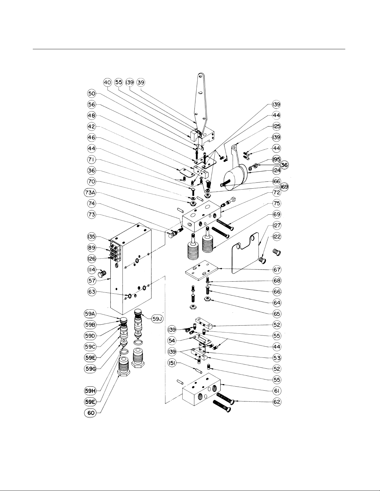
Instruction Manual
Form 1387
June 2002
350 Actuator
DH4709-G/DOC
Figure 11. Amplifier Assembly with Optional Lock Valves
(Lock Valves—Keys 59A through 60)
27
Page 29

350 Actuator
A
VALVE B
RESTRICT STROKING TIME TO
EXTEND PISTON ROD
Instruction Manual
Form 1387
June 2002
30A6482-B/DOC
A
SECTION A-A
VALVE B
RESTRICT STROKING TIME TO
RETRACT PISTON ROD
SECTION A-A
B
WITHOUT LOCK VALVES WITH LOCK VALVES
Figure 12. Optional Speed Control Valve
NOTE:
LEVER PIN (KEY 153) REPLACED BY ENGAGING PIN ON DECLUTCHABLE HANDWHEELS
1
APPL Y LUB/SEALANT
40A8779-D/DOC
Figure 13. Typical Bolt-On Handwheel (Non-Declutchable Type is Shown)
28
1
Page 30

Instruction Manual
Form 1387
June 2002
350 Actuator
50A6748-F/DOC
Figure 14. 127 mm (5-Inch) Yoke Boss Size Type 350 Actuator with Integral Handwheel
29
Page 31

350 Actuator
Instruction Manual
Form 1387
June 2002
Key Description Part Number
90 mm (3-9/16 Inch) Yoke Boss Bolt-On Handwheel
51 Handwheel, cast iron
54 Hex Jam Nut, pl steel
55 Ball, alloy steel
56 Spring, bronze
132 Operating Nut, steel
136 Bearing Retainer, steel
142 Handwheel Body, cast iron/bronze
143 U-Bolt, steel
144 Hex Nut, pl steel
145 Handwheel Screw, bronze
146 Lever & Pin Ass’y, steel/bronze
148 Dowel Pin, steel
149 Washer, pl steel
150 Lockwasher, steel
152 Ball Bearing, steel
153 Lever Pin, 416 SST
154 Retaining Ring, steel
154 Cotter Pin, steel
155 Spacer, steel
156 Cap Screw, steel
158 Hex Nut, pl steel
159 Pointer Mtg Bolt, 416 SST
160 Pointer, 302 SST
161 Machine Screw, steel
162 Indicator, aluminum
163 Cap Screw, steel
166 U-Bolt, steel
167 Guide Bolt, 416 SST
168 Set Screw, steel
169 Grease Fitting Non-declutchable
170 Hex Nut, pl steel
172 Chain, SST
173 Drive Screw, steel
177 Spring Cap, steel
178 Machine Screw, steel
241 Lubricant, Lubriplate Mag 1
127 mm (5-Inch) Yoke Boss
Integral Handwheel
159 Locking Pin, 416 SST HT
170 Sleeve Ass’y, 416 SST
171 Set Screw, alloy steel
172 Gear Case, cast iron
173 Thrust Bearing
174 Worm Gear, bronze
175 Retainer, steel
Key Description Part Number
176 Cap Screw, pl steel
177 Key, steel
178 Travel Stop Nut, steel
179 Front Worm Retainer Steel
180 Back Worm Retainer Steel
181 Worm Shaft, steel
182 Handwheel cast iron
183 Handgrip, steel
184 Handgrip Bolt, steel
185 Handwheel Cap, Cast iron
186 Set Screw, steel
187 Grease Fitting
188 Ball, alloy steel
189 Spring, bronze
190 Ball Bearing
191 Hex Nut, pl steel
193 Adaptor, cast iron
197 Pointer, SST
199 Cap Screw, steel
226 Machine Screw, steel
90 mm (3-9/16 Inch) Yoke Boss Integral Handwheel
171 Set Screw, steel
174 Worm Gear, bronze
177 Key, steel
179 Front Worm Retainer, steel
180 Back Worm Retainer, steel
181 Worm Shaft, steel
182 Handwheel, cast iron
183 Hand Grip, steel
184 Hand Grip Bolt, steel
185 Handwheel Cap
186 Set Screw, steel
187 Grease Fitting
188 Ball, alloy steel
189 Spring, bronze
190 Ball Bearing, steel
197 Handwheel Indicator SST
226 Machine Screw, pl steel
227 Actuator Stem 316 SST
228 Upper Sleeve, steel
229 Needle Bearing, steel
230 Needle Bearing Race, steel
231 Bearing Retainer Flange, Cast iron
232 Needle Bearing, steel
233 Needle Bearing Race, steel
234 Lower Sleeve, steel
235 Cover Band Ass’y, steel
236 Cap Screw, pl steel
237 Washer, brass
240 Plate, steel
30
Page 32

Instruction Manual
Form 1387
June 2002
350 Actuator
31
Page 33

350 Actuator
Instruction Manual
Form 1387
June 2002
Fisher is a mark owned by Fisher Controls International, Inc., a business of Emerson Process Management. The Emerson logo is a
trademark and service mark of Emerson Electric Co. All other marks are the property of their respective owners.
The contents of this publication are presented for informational purposes only, and while every effort has been made to ensure their accuracy,
they are not to be construed as warranties or guarantees, express or implied, regarding the products or services described herein or their use
or applicability. We reserve the right to modify or improve the designs or specifications of such products at any time without notice.
Fisher does not assume responsibility for the selection, use or maintenance of any product. Responsibility for proper selection, use and
maintenance of any Fisher product remains solely with the purchaser and end-user.
Emerson Process Management
Fisher
Marshalltown, Iowa 50158 USA
Cernay 68700 France
Sao Paulo 05424 Brazil
Singapore 128461
www.Fisher.com
32
EFisher Controls International, Inc. 1976, 2002; All Rights Reserved
 Loading...