

Emerson 3700, 3500 Installation Manual

Installation Manual
20001008, Rev BC
March 2021
Micro Motion® Model 3700 Transmitter
(MVD) or Model 3350 Peripheral
Installation manual for field mount

Safety and approval information
This Micro Motion product complies with all applicable European directives when properly installed in accordance with the
instructions in this manual. Refer to the EC declaration of conformity for directives that apply to this product. The EC declaration of
conformity, with all applicable European directives, and the complete ATEX Installation Drawings and Instructions, in addition to the
IECEx Installation Instructions for installations outside of the European Union and the CSA Installation Instructions for installations in
North America a
Information affixed to equipment that complies with the Pressure Equipment Directive can be found on the internet at
www.micromotion.com/documentation.
For hazardous installations in Europe, refer to standard EN 60079-14 if national standards do not apply.
Other information
Full product specifications can be found in the product data sheet. Troubleshooting information can be found in the transmitter
configuration manual. Product data sheets and manuals are available from the Micro Motion web site at www.micromotion.com/
documentation.
Return policy
Micro Motion procedures must be followed when returning equipment. These procedures ensure legal compliance with government
transportation agencies and help provide a safe working environment for Micro Motion employees. Failure to follow Micro Motion
procedures will result in your equipment being refused delivery.
Information on return procedures and forms are available on our web support system at www.micromotion.com, or by phoning the
Micro Motion Customer Service department.
Emerson Flow customer service
Email:
• Worldwide: flow.support@emerson.com
• Asia-Pacific: APflow.support@emerson.com
re available on the internet at www.micromotion.com or through your local Micro Motion support center.
Telephone:
North and South America Europe and Middle East Asia Pacific
United States 800-522-6277 U.K. 0870 240 1978 Australia 800 158 727
Canada +1 303-527-5200 The Netherlands +31 (0) 704 136 666 New Zealand 099 128 804
Mexico +41 (0) 41 7686 111 France 0800917901 India 800 440 1468
Argentina +54 11 4837 7000 Germany 0800 182 5347 Pakistan 888 550 2682
Brazil +55 15 3413 8000 Italy 8008 77334 China +86 21 2892 9000
Venezuela +58 26 1731 3446 Central & Eastern +41 (0) 41 7686 111 Japan +81 3 5769 6803
Russia/CIS +7 495 981 9811 South Korea +82 2 3438 4600
Egypt 0800 000 0015 Singapore +65 6 777 8211
Oman 800 70101 Thailand 001 800 441 6426
Qatar 431 0044 Malaysia 800 814 008
Kuwait 663 299 01
South Africa 800 991 390
Saudia Arabia 800 844 9564
UAE 800 0444 0684

Contents
Contents
Chapter 1 Planning....................................................................................................................... 5
1.1 Installation kit ........................................................................................................................ 5
1.2 Choose a location................................................................................................................... 6
1.3 Cable lengths ......................................................................................................................... 8
1.4 Prepare conduit openings for ATEX Zone 1 or IECEx Zone 1...................................................... 9
1.5 (Optional) Orient the Model 3350 or Model 3700 .................................................................. 9
Chapter 2 Mounting..................................................................................................................... 11
2.1 Mount the applications platform............................................................................................ 11
2.2 Mount the core processor ...................................................................................................... 13
Chapter 3 Wiring ......................................................................................................................... 15
3.1 Connect input and output wiring ........................................................................................... 15
3.2 Connect the Model 3700 to the sensor .................................................................................. 17
3.3 Wire the sensor to the remote core processor........................................................................ 22
3.4 Connect the power supply wiring........................................................................................... 24
Installation Manual 3

4 Model 3700 Transmitters or Model 3350 Peripherals - Field Mount
1 Planning
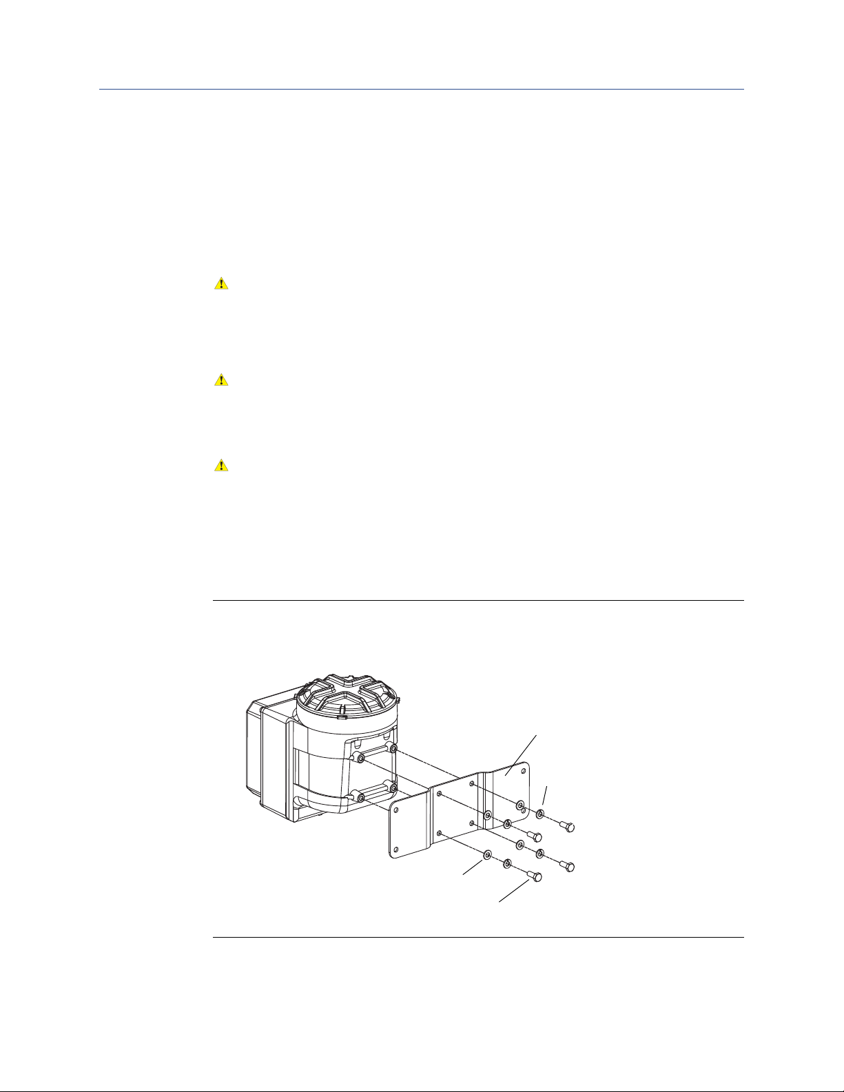
4 x flat washer
4 x Lock washer
4 x M8x16 bolt assemblies
Mounting bracket
You can orient the transmitter on
the bracket. See Section 1.5.
This installation manual explains basic installation guidelines for installing the Micro Motion
Model 3350 or Model 3700 MVD applications platform.
For information on I.S. applications, refer to Micro Motion approval documentation.
For complete instructions about configuration, maintenance, and service, refer to the
instruction manual shipped with the transmitter.
WARNING!
Improper installation in a hazardous area can cause an explosion.
For information about hazardous applications, refer to the appropriate Micro Motion approval
documentation, shipped with the meter or available from the Micro Motion web site.
WARNING!
Hazardous voltage can cause severe injury or death.
Install transmitter and complete all wiring before supplying power.
CAUTION!
Improper installation can cause measurement error or meter failure.
Follow all instructions.
Planning
1.1 Installation kit
The Model 3350 or Model 3700 installation kit includes the parts shown in Figure 1-1.
Figure 1-1: Field-mount installation kit
Installation Manual 5
Planning
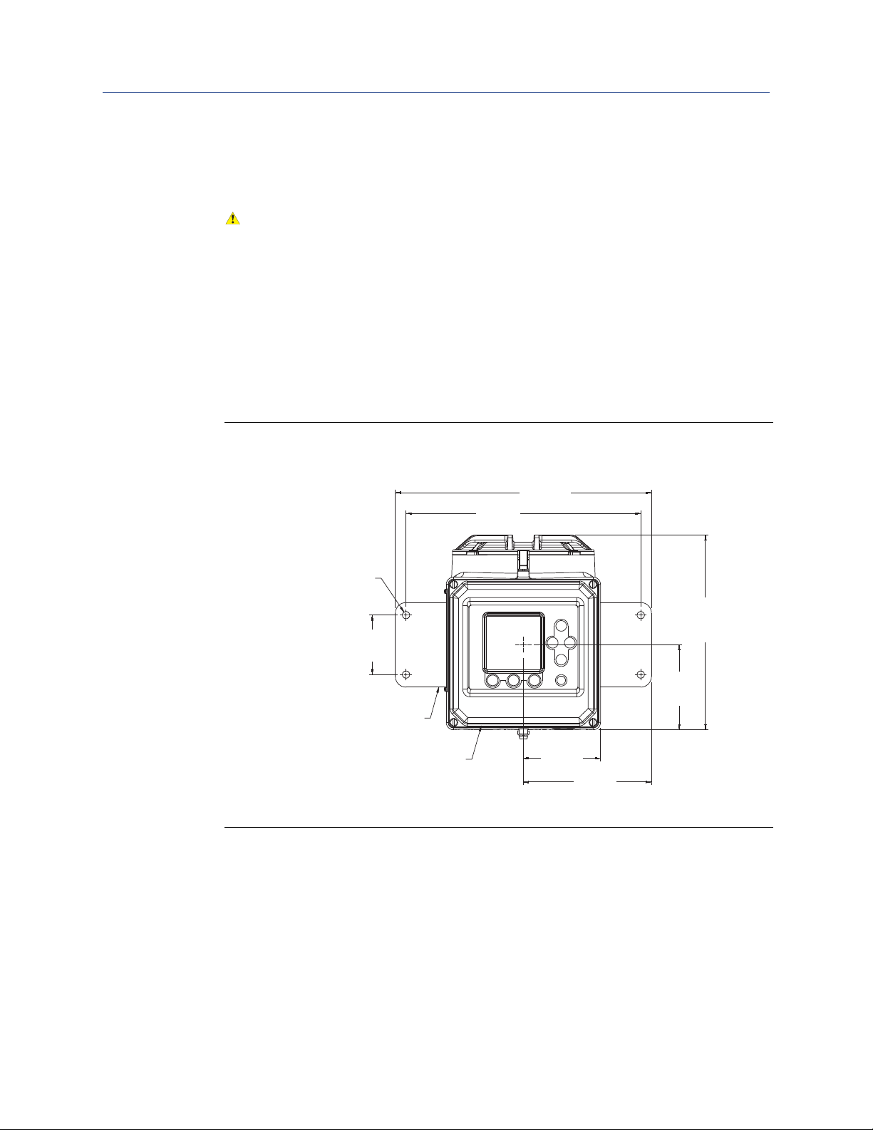
inches (mm)
Rotate display cover as needed
Rotate mounting bracket as
needed
2 13/16
(71)
4 x 5/16-inch
(9 mm) diameter
9 3/16
(234)
4
(102)
3 5/8
(92)
6
(152)
11
(279)
12
(305)
1.2 Choose a location
Choose a location for the transmitter based on the requirements described below.
WARNING!
Improper installation in a hazardous area can cause an explosion.
Install the transmitter in an area that is compatible with the rating on the approvals tag. See Figure
1-3.
1.2.1 Environmental requirements
Install the Model 3350 or Model 3700 where the ambient temperature is between –4 to
+140 °F (–20 to +60 °C).
1.2.2 Dimensions
Figure 1-2: Face view dimensions
6 Model 3700 Transmitters or Model 3350 Peripherals - Field Mount
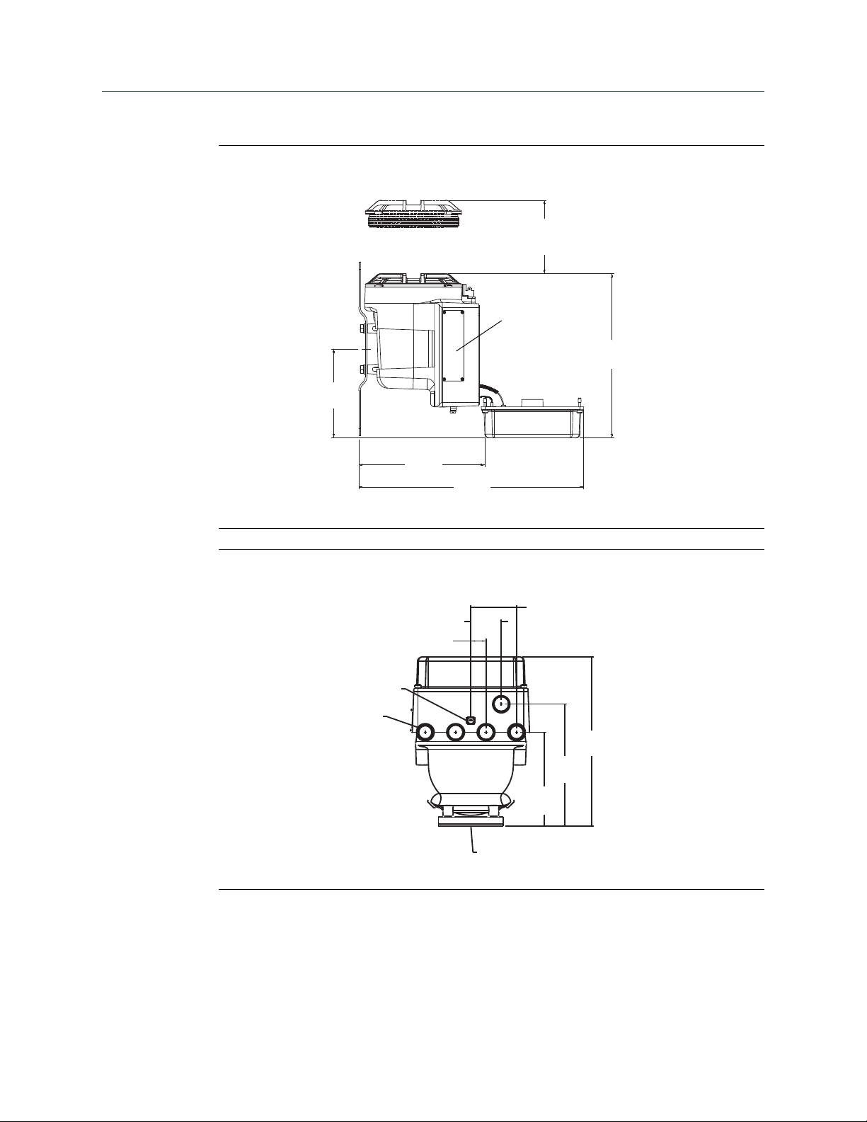
Figure 1-3: Top view dimensions
Approvals tag
5 1/16-inch (129 mm) clearance for
removal of circuit boards
inches
(mm)
11 5/16
(288)
6 1/8
(158)
15 1/2
(394)
8 11/16
(221)
5 x 3/4-14 NPT or
5 x M20 x 1.5- 6H
Case ground
Mounting surface
inches
(mm)
2 x 15/16
(24)
1 7/8
(48)
2 x 2 13/17
(71)
10 3/8
(265)
7 1/2
(191)
5 3/4
(147)
Planning
Figure 1-4: Conduit openings view dimensions
Installation Manual 7
Planning
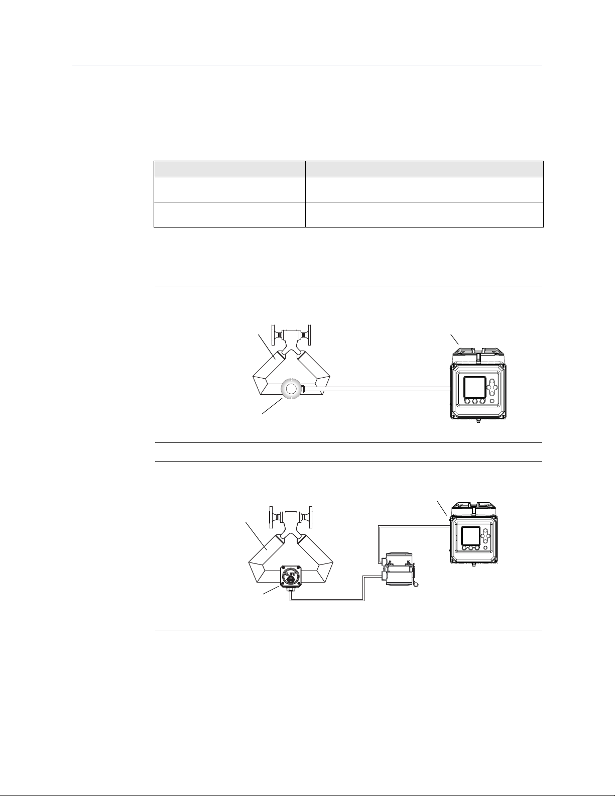
Model 3700
4-wire cable
Sensor
Core processor
(standard or enhanced)
1.3 Cable lengths
Maximum cable length from the sensor to the Model 3700 transmitter depends on the
installation type and cable type.
Installation type Maximum cable length
4-wire remote transmitter See Figure 1-5, and Table 1-1 for maximum length of the
Remote core processor with remote
transmitter
If you are installing the Model 3350 controller in combination with a transmitter, the
maximum cable length between the transmitter frequency output and the Model 3350
frequency input is 500 feet (150 meters).
Figure 1-5: 4-wire remote transmitter
4-wire cable
See Figure 1-6, and Table 1-1 for maximum length of the
4-wire cable and the 9-wire cable
Figure 1-6: Remote core processor with remote transmitter
Model 3700
Sensor
4-wire cable
Junction box
8 Model 3700 Transmitters or Model 3350 Peripherals - Field Mount
9-wire cable
Core processor
 Loading...