

Page 1
16E09-201
!
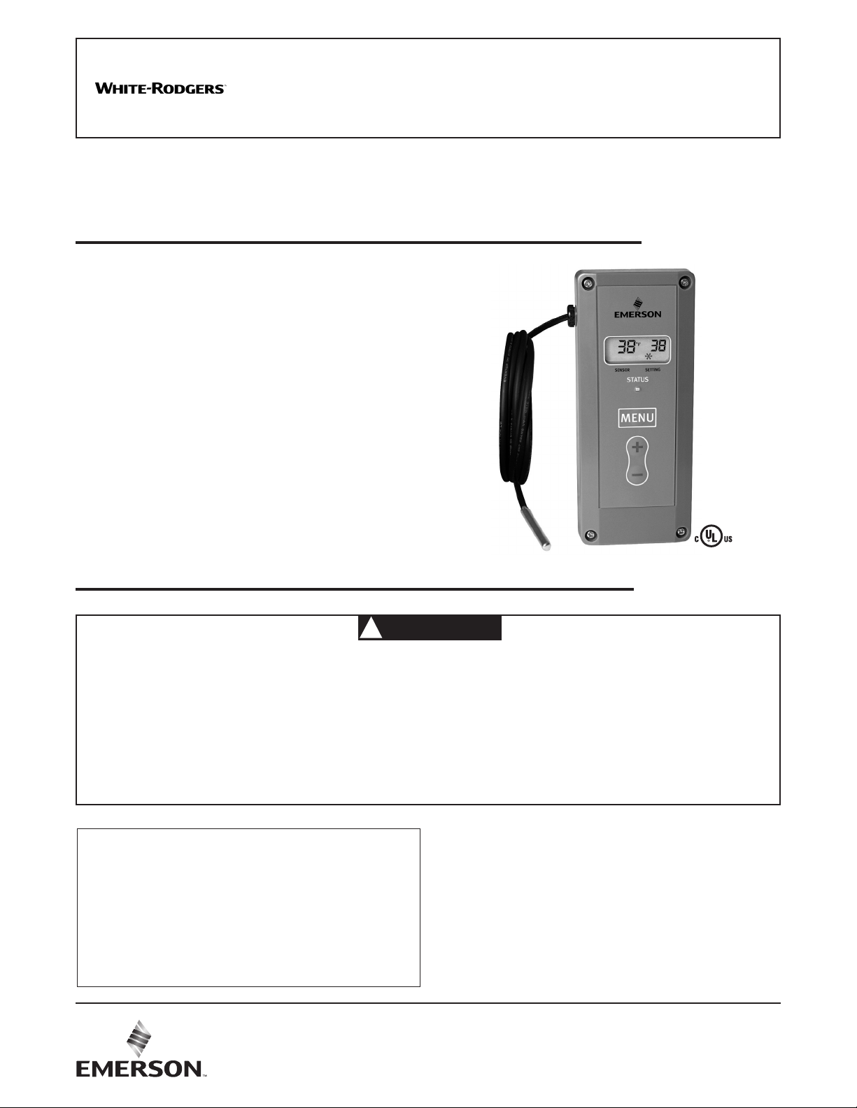
Universal Electronic Temperature Control
INSTALLATION AND
OPERATION INSTRUCTIONS
FAILURE TO READ AND FOLLOW ALL INSTRUCTIONS CAREFULLY
BEFORE INSTALLING OR OPERATING THIS CONTROL COULD CAUSE
PERSONAL INJURY AND/OR PROPERTY DAMAGE.
DESCRIPTION
The 16E09-201 is a single stage electronic temperature control, with a Nema 1 rated enclosure, and can be used for most
applications within the temperature control range of -40° to
220°F, (-40° to 104°C). The control has an SPDT (Single Pole
Double Throw) output load relay.
The control has user options to control differential, anti-short
cycle delay, set back, offset, alarms and more. It includes an
NTC (Negative Temperature Coefficient) thermistor temperature sensor, and can be used with certain other NTC or PTC
(Positive Temperature Coefficient) thermistors that meet the
specified resistance vs. temperature specifications. See the
tables on page 7.
The control can fit many applications, which range from
refrigeration to heating due to the wide temperature range of
the control stated above. Typical applications include walkin freezers, beverage coolers, supermarket display cases
for flowers, produce, meats, convenience store refrigerated
cases, food warmers, boiler control, and certain industrial
applications.
PRECAUTIONS
WARNING
• Failure to read and follow all instructions carefully before
installing or operating this control could cause personal
injury and/or property damage.
• To prevent electrical shock, personal injury and/or
equipment damage, disconnect electric power to system
at main fuse or circuit breaker box prior to installation
or service.
CONTENTS
Basic Description ........................................................ 1
Precautions ................................................................. 1
Installation ................................................................... 2
Wiring .......................................................................... 3
User Menu .................................................................. 3
Operation .................................................................... 4
Specifications .............................................................. 6
Troubleshooting ........................................................... 6
• To prevent scald injury, do not use this control to
heat water for bathing, washing, hot tub or similar
applications.
• Where failure of this control may result in personal
injury and/or property damage, additional alarms or limit
controls must be installed.
• This control is a temperature control and is not to be
used as a temperature limit control.
16E09-201 Optional Accessories / Service Items:
Immerson Well .................................................... F89-0286
Replacement 7.5' NTC Remote Sensor .............. F136-0114
Well Heat Transfer Compound ............................. F145-0163
PART NO. 37-7809001
2006emerson.com/white-rodgers
Page 2
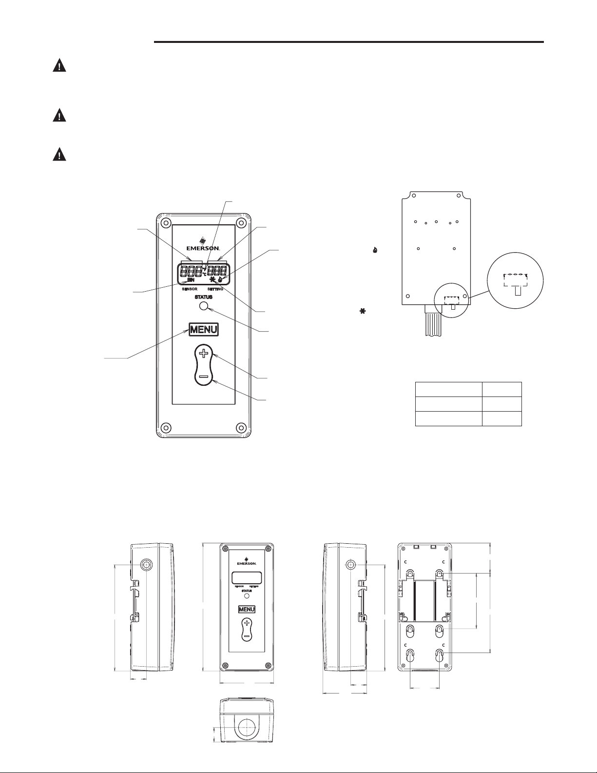
FRONT VIEW
BOTTOM VIEW
RIGHT SIDE VIEW
REAR VIEW
6.73”
2.8”
.76”
5.59”
.85”
2.54”
1.54”
2.91”
4.19”
1.58”
LEFT SIDE VIEW
.85”
5.59”
COOL
HEAT
SW1
COOL
HEAT
SW1
TEMPERATURE UNITS INDICATOR (°F or °C)
ACTUAL TEMPERTURE
AT TEMPERATURE SENSOR
SETPOINT TEMPERATURE
HEATING MODE INDICATOR ( )
COOLING MODE INDICATOR ( )
BINARY INPUT INDICATOR
LIT WHEN UNIT IS IN
“SETBACK” MODE
REFER TO PAGE 6
STATUS INDICATOR LED
LIT WHEN CONTROLLED LOAD
IS ENERGIZED (ON).
(SEE NOTE)
TEMPERATURE “UP” BUTTON
TEMPERATURE “DOWN” BUTTON
MENU BUTTON
PRESS TO ENTER MENU MODE
REFER TO PAGES 4 & 5
INSTALLATION
To prevent electrical shock and/or equipment dam-
age, disconnect electric power to system at main
fuse or circuit breaker box prior to installation or
service.
Where failure of this control may result in personal
injury and/or property damage, additional alarms or
limit controls must be installed.
This control is a temperature control and is not to
be used as a temperature limit control.
Fig. 1 Control Front View and Description
The control has a user selection for changing the setpoint to
be either the Cut In or the Cut Out setting. The user must be
careful to understand how this effects the “range” in which
the control will operate when the differential value is entered.
If entered values are incorrect, the control could operate
outside the user’s intended settings due to set-up error. See
section titled "Operation".
Circuit Board
Inside Cover
NOTE:
Green Status Indicator LED and display backlight operation
It may be observed from time to time that the green status indicator LED and
display back-light will briefly turn off during a call for heating or cooling. During this
time, the control is performing a self-check lasting up to 15 seconds. This is normal
operation of the control and the load power will be maintained
Fig. 2 Control Dimensions and Mounting Information
Switch SW1 must be set for
system mode as shown:
SW1
Refrigeration Cool
Heating Heat
2
Page 3
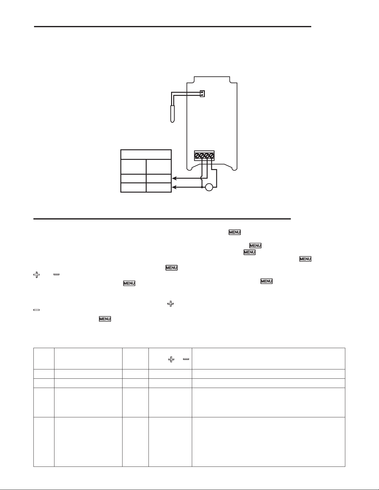
WIRING
Fig. 3 Line Voltage Application
Load
Wiring Instruction Notes
(Non-Power Stealing)
NTC
NTC*
Temperature
Sensor
Voltage Input
120 VAC
Hot
Neutral
* NTC – Negative Temperature Coefficient
208/240
VAC
L1
L2
NC
NEUT
LINE
LOAD
USER MENU
USER MENU OPERATION SETTINGS:
The control has user Menu settings that will determine
how the control operates. The unit is shipped with factory
default settings. The user must change any of the settings
as required for the application. To reset all settings to factory
defaults, press and hold all 3 buttons simultaneously ( ,
, and buttons) for approximately 5 seconds.
To view Menu items, press and hold for 5 seconds.
The unit will display the first Menu item on the left side of the
display. The right side of the display indicates the Menu item
settings. To change the setting, momentarily press the or
key.
A momentary press of the key advances the display to
the next Menu item, and continues, till the last menu item is
displayed. Pressing the key one more time with the last menu
item, (aL) displayed returns the control to the operating mode.
Menu
Item Description
CF Temperature Scale F C or F Selects temperature display in Fahrenheit or Celsius
dFF Differential 5 1 to 30 Selects the range between Cut In and Cut Out.
SP Set Point Mode
Cool
Heat
SOF Sensor Operation Failure
Cool
Heat
Factory
Default
Cl
CO
1
0
Each press of results in forward movement to the next
Menu item. If you need to change an item “passed”, you
must repeatedly press , return to the operating mode,
then press and hold for 5 seconds to re-enter the Menu
mode. Then repeatedly, momentarily press until the
desired Menu item is again displayed.
To store any changes made to any Menu items, the Menu
must be exited by pressing when the last item is
displayed. If no buttons are pressed for ten minutes while in
the menu, the control will return to operating mode and any
changes that were made will be lost.
The following table shows the menu items, default settings
and optional settings.
NOTE: The Heat/ Cool switch (SW1) MUST be in the proper
position BEFORE setting options.
Options
Press or
to select Comments
CO or CI
CI or CO
0 or 1
None
Selects how the set point temperature will operate the load
terminal. CI indicates the setpoint temperature will be the
Cut In temperature. CO indicates the temperature will be the
Cut Out temperature. See Operation section.
Cooling - Selects the operation of the Control Load relay in
the event of a sensor failure in Cool mode. 1 (default) will
cause the load contacts of the relay to close and remain
closed if the sensor either opens or shorts. 0 causes the
load contacts of the relay to open and remain open.
Heating has no optional selection. Sensor failure
in Heating will result in the relay contacts opening.
3
Page 4
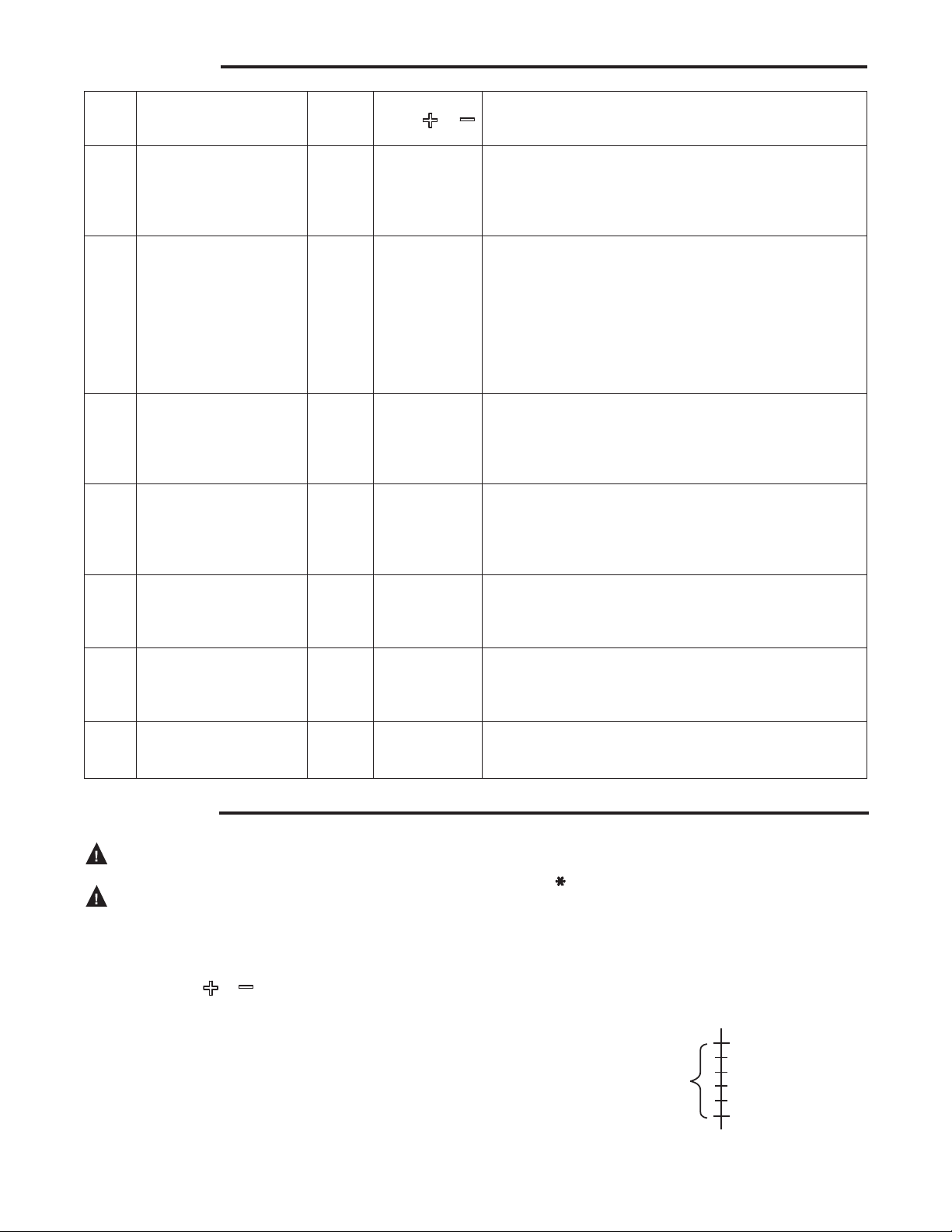
USER MENU
SW1 = Cool
Set Point (SP) = Cut In
Dif
Setpoint temperature = 40°
Options
Menu
Item Description
dL Display Light Off On or Off Selects the LCD display light Off or On. With this selected
ASd Anti Short-Cycle Delay Cool
LP Lock Front Panel Keypad Off On or Off When selected Off, the keypad can be used as normal.
OFS Ambient Temperature
Offset
bIn Binary Input Off On or Off The default setting of Off will have no affect on the opera-
Sb Set Back 0 0 to 50 Selects the number of degrees the thermostat will change
AL Alarm 0 0 to 99 Selects the time delay (in minutes) before a Temperature
Factory
Default
Heat
Press or
to select Comments
0 to 12 Selects the minimum time (in minutes) that the load con-
1
0
0 -4, -3, -2, -1, 0,
1, 2, 3, 4
Off, the display light will illuminate any time a keypad button
is pressed to provide better viewing in low lighting conditions, and go off after 10 seconds. If On is selected, the
display light will be On continuously.
tacts will remain open after a cycle before closing again.
This will prevent the compressor or other load from being damaged by cycling too soon. A blinking Snowflake
or Flame icon indicates that the control has a demand to
energize the load, but is waiting for the delay time to elapse.
A setting of 0 indicates no time and the feature is disabled.
SW1 must be set to the proper position before checking this
setting.
When selected On, prevents unauthorized access to the
control settings by locking out all keys. To unlock the control
when it is locked, press and hold the Menu key for 5 seconds.
This control is calibrated at the factory, but the “sensed"
temperature may read different because of mounting/installation, or other factors. This item allows the displayed
temperature to be shifted the number of degrees set to
compensate for this difference
tion of the thermostat. When set to On, it allows an external
binary input (switch or relay) to start a temperature set back.
See Set Back (Sb).
the setpoint temperature when the external binary input
signal is received. 0 will cause no temperature change to
occur. See Binary Input (bin).
Out of Range alarm output is sent.
A setting of 0 disables the alarm relay.
OPERATION
This control is a temperature control and is not to
be used as a temperature limit control.
To prevent scald injury, do not use this control to
heat water for bathing, washing, hot tub or similar
applications.
The factory default setpoint for this control is 45°F (7°C) for
Cool and 120°F (49°C) for Heat. Setpoint temperature can be
adjusted using the or keys. A power loss does not lose
the settings. All menu item selections and setpoint setting are
stored in a permanent memory.
The user determines the temperature operating range. To
determine the temperature range, the user must select
the Set Point (SP) as the Cut Out or Cut In temperature,
Differential (dFF) and enter a set point temperature. Cut out
is when the load is turned off and cut in is when the load is
turned on.
NOTE: The Heat/ Cool switch (SW1) MUST be in the proper
position BEFORE setting options.
4
COOL/REFRIGERATION
To use as a Cooling control, SW1 must be set to Cool. The
snowflake ( ) icon will display.
If control is in Cool mode, and Set Point is selected as the
Cut In:
Temperature
Operating = Setpoint – Differential
Range Temperature
Example:
ferential = 5
(minus)
Range
Temperature
40° Setpoint (Cut In)
35°
Page 5
40° Setpoint (Cut Out)
SW1 = Cool
Set Point (SP) = Cut Out
Dif
Setpoint temperature = 40°
100° Setpoint (Cut Out)
SW1 = Heat
Set Point (SP) = Cut Out
Dif
Setpoint temperature = 100°
100° Setpoint (Cut In)
SW1 = Heat
Set Point (SP) = Cut In
Dif
Setpoint temperature = 100°
OPERATION
3
4
Sensor
Sensor
If control is in Cool mode, and Set Point is selected as the
Cut Out:
Temperature
Operating =
Range
Example:
ferential = 5
Setpoint
Temperature
+ Differential
(plus)
Range
Temperature
45°
HEAT
To use as a Heating control, SW1 must be set to Heat. The
flame ( ) icon will display.
If control is in Heat mode, and Set Point is selected as the
Cut Out:
Temperature
Operating =
Range
Example:
ferential = 5
If control is in Heat mode, and Set Point is selected as the
Cut In:
Temperature
Operating =
Range
Example:
ferential = 5
Setpoint
Temperature
Setpoint
Temperature
– Differential
+ Differential
(minus)
Range
Temperature
(plus)
ane
emperature
95°
105°
Lock Panel (LP)
The keypad can be locked to prevent unwanted tampering
with the control settings. In the User Menu, change the menu
item LP selection to On. When the menu is exited and settings are stored, the or , and keys will be disabled
from normal use.
To unlock the keypad, press and hold for 5 seconds.
The display will change to show LP On. Momentarily press
or to change to Off and then momentarily press .
The control will return to normal operation and the keypad
will be unlocked.
Binary Input (bIn) and Set Back (Sb)
Binary Input is an option to allow the setpoint temperature
to set back to conserve energy or for other reasons as
determined by the user. Set Back determines the number of
degrees the setpoint temperature will be changed.
An external switch or N.O. relay can be connected to the BIN
and GND terminals of the control. With bIn set to On, when
the switch is closed, the control will change the setpoint temperature by the number of degrees set in Sb. In Heat mode,
setpoint temperature will change lower or cooler. In Cool
mode, setpoint temperature will change higher or warmer.
During the time that the switch is closed, bIn will appear in
the lower left corner of the display. If an alarm is connected
be sure that the alarm delay time is set long enough to allow
for the temperature change to avoid a “false” alarm.
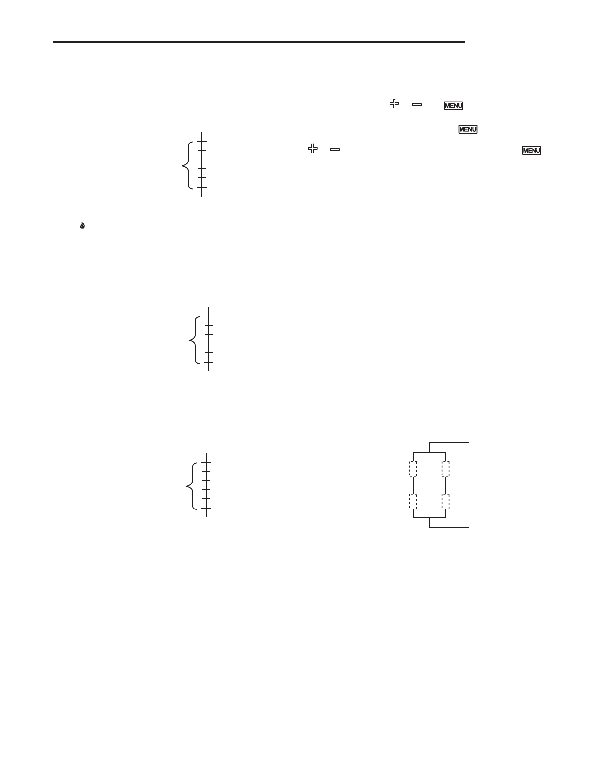
Multiple Sensors
The 16E09 is normally operated with one sensor. If an average temperature of an area is required, 4 sensors may be
used and wired in the method shown below. If 4 sensors are
used, they must all be of the same model.
1
2
Sensor
Sensor
NOTE: When using multiple sensors, 4 sensors must be
used. The control will not operate with 2 or 3 sensors.
5
Page 6

SPECIFICATIONS
Load Output Relay: Ratings (Maximum):
120VAC 208VAC 240VAC
Full Load Amps NC & Load 16 A 9.2 A 8 A
Locked Rotor Amps NC & Load 96 A 55.2 A 48 A
Non-Inductive Amps NC & Load 16 A 16 A 16 A
Horsepower NC & Load 1 hp 1 hp 1 hp
Pilot Duty NC & Load 125 VA, 240 VAC
• Minimum Load Rating: 1 Amp @ 120 VAC
• Note: the above minimum current/voltage is specified
to assure proper operation.
NOTE: For use on single phase circuits only.
Alarm Relay Ratings (Maximum):
N.O. contact: 1 Amp, 5 to 24 V, AC or DC
Temperature Probes:
NTC
The control is shipped with an NTC (Negative Temperature
Coefficient) sensor, with a cable length of 7½ feet. Cable
length can be extended up to 400 feet by appropriately splicing and adding additional cable (22 AWG or larger diameter)
NTC TEMPERATURE VERSUS RESISTANCE TABLES
Temperature
(°F) (°C)
-40 -40 328.29
-31 -35 236.83
-22 -30 172.90
-13 -25 127.65
-4 -20 95.23
5 -15 71.74
14 -10 54.56
23 -5 41.85
32 0 32.37
41 5 25.23
Resistance
(KΩ)
Temperature
(°F) (°C)
50 10 19.82
59 15 15.67
68 20 12.48
77 25 10.00
86 30 8.07
95 35 6.55
104 40 5.34
113 45 4.38
122 50 3.61
131 55 2.99
Operating Ambient Ratings (Control Enclosure):
Operating Temperature: -29°F to 140°F (-34° to 60°C)
Storage Shipping Ambient Ratings:
Storage Temperature: -40°F to 185°F (-40° to 85°C)
Operating Humidity: 0 to 95% Relative Humidity,
Non-Condensing
Maximum Dew Point: 85°F (29°C)
Temperature Set-Point Range:
Set-Point Range: -40° to 220°F (-40° to 104°C)
Differential Range: 1 to 30 (Degrees F or Degrees C)
Case:
NEMA 1 Enclosure, Flammability Rating: UL94VO
as needed – polarity is not important. When extending cable
length, verify temperature accuracy and use the menu Ambient Temperature Offset (OFS) settings to compensate accordingly if required.
Resistance
(KΩ)
Temperature
(°F) (°C)
140 60 2.49
149 65 2.09
158 70 1.76
167 75 1.48
176 80 1.26
185 85 1.07
194 90 0.92
203 95 0.79
212 100 0.68
221 105 0.59
Resistance
(KΩ)
TROUBLESHOOTING
LCD display, display back-light and green status indicator LED turn off in Power Stealing mode:
This “off” condition is normal for the control in power stealing
mode when wired with a defrost timer or other device that
interrupts electrical power to the control.
No control settings will be lost during this time, however, the
installer must ensure that applications requiring power stealing are suitable for the control to be off during these periods.
Please note: if the built-in alarm feature of the control is to
be used on systems that may interrupt power to the control,
the control must be wired with a neutral wire and set in nonpower stealing mode. This will keep the control continuously
powered unless there is an actual power interruption or loss.
In this case, the control will be able to signal an alarm for
system power loss.
6
Display indicates “CaL” on power up.
Control was not calibrated. Return control for replacement.
Unit does not turn on, (LCD does not display anything):
- Check that wiring is correct.
- Make sure power is turned on.
- Check that wiring is under terminal blocks correctly.
- Make sure both switches inside control are set to proper
position.
Temperature differential is wider than set:
- Temperature change of customer's unit is fast, and the
Anti Short Cycle delay setting may be overriding the “call”
to activate the heat or cool. Solution – lower Anti Short
Cycle delay.
Page 7

NOTES
7
Page 8

Emerson and White-Rodgers are
trademarks of Emerson Electric Co.
©2020 Emerson Electric Co.
All rights reserved.
TECHNICAL SUPPORT: 1-888-725-9797
emerson.com/white-rodgers
 Loading...