

Page 1
Instruction Manual
Form 2256
December 2008
168, 168H, and 68 Series
168, 168H, and 68 Series Three-Way
Switching Valves
Introduction
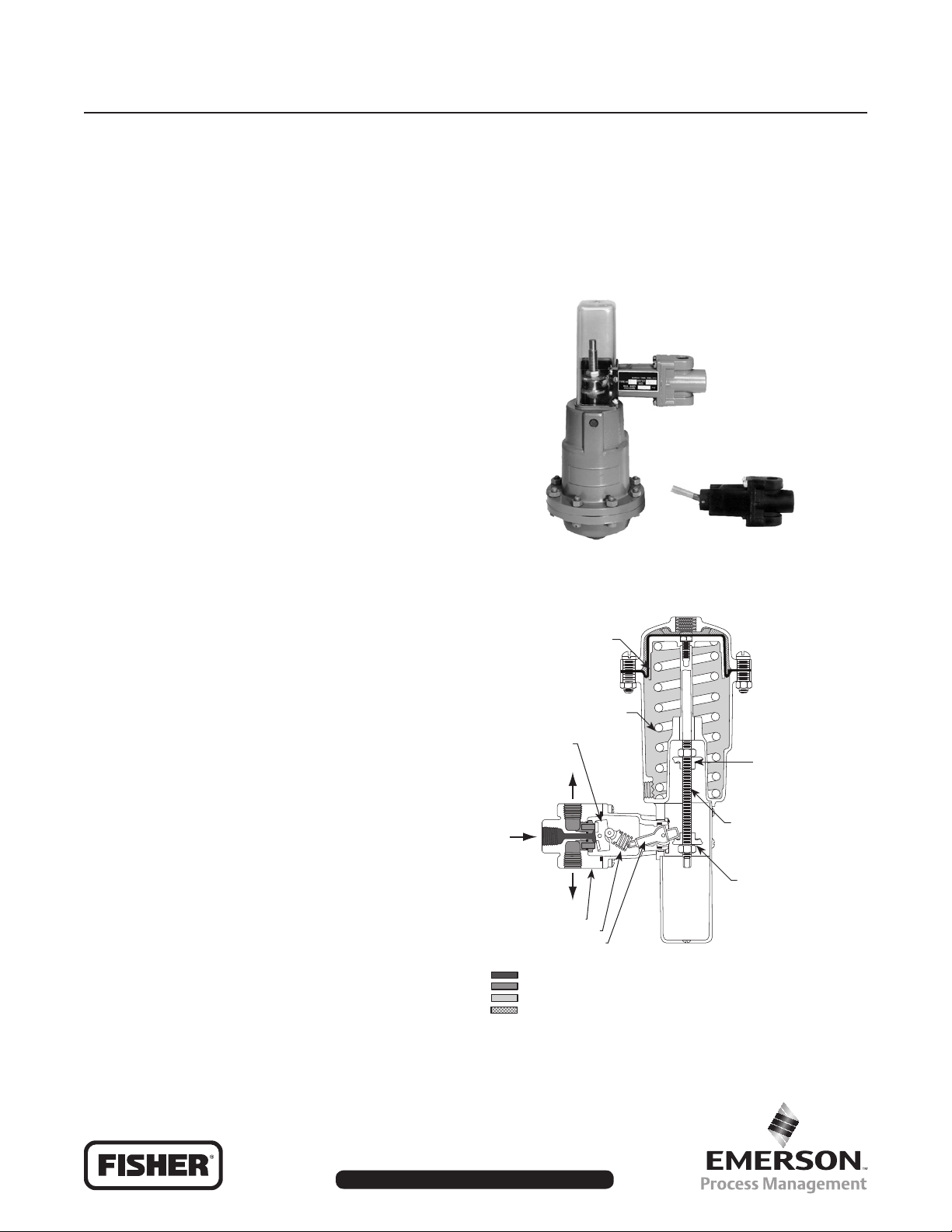
The 168 and 168H Series pneumatically operated
three-way snap-acting switching valves (Figure 1) are
used to switch pressures on and off in response to a
predetermined change in an input signal pressure.
In operation, increasing pressure applied to the top of
the diaphragm through port D (see Figure 2) moves
the stem and upper range adjusting nut toward the
trip lever. When the diaphragm pressure reaches
the predetermined upper tripping pressure, the upper
adjusting nut pivots the trip lever to move the rocker
assembly to its alternate position, closing port C
and opening port B. When decreasing pressure to
the diaphragm at port D reaches the lower tripping
pressure, the spring moves the stem and lower range
adjusting nut to return the rocker to its original position,
closing port B and opening port C.
W1932
Figure 1. Exterior of 168 Series Switching Valve
D
The 68 Series (Figure 4) three-way snap-acting body
assemblies can be used alone, or to form the valve
body portions of 168 or 168H Series switching valves.
With the addition of the lever knob (key 11, Figure 4)
to a Type 68-1 body assembly, a Type 68-2 manual
switching valve body assembly is formed.
Only personnel qualied through training or experience
should install, operate, and maintain these valves. If
there are any questions concerning these instructions,
contact your local Sales Ofce before proceeding.
DIAPHRAGM
DIAPHRAGM
SPRING
B
C
BODY
BODY SPRING
TRIP LEVER
INLET PRESSURE
OUTLET PRESSURE
ATMOSPHERIC PRESSURE
LOADING PRESSURE
A
M1045
ROCKER
ASSEMBLY
UPPER RANGE
ADJUSTMENT NUT
STEM
LOWER RANGE
ADJUSTMENT NUT
Figure 2. Construction Details of
168 Series Switching Valve
www.emersonprocess.com/regulators
D100275X012
Page 2
168, 168H, and 68 Series
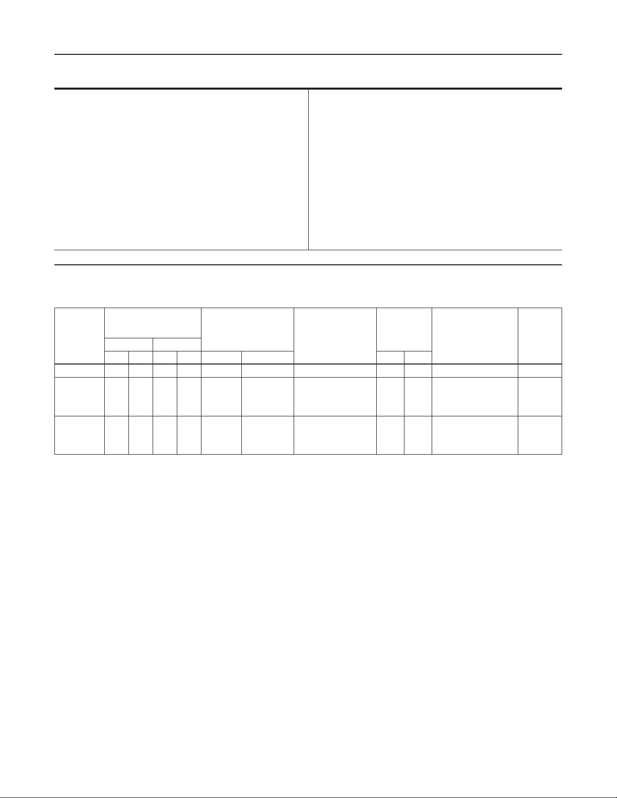
Specications
Maximum Allowable Pressures
Diaphragm
168 Series: 100 psi (6,90 bar)
Flow Coefcients
Cg: 7
Representative C1: 35
168H Series: 150 psi (10,3 bar)
Body: See Table 1
Operative Temperature Limits
(1)
-10° to 150°F (-23° to 66°C)
Port Diameter
3/32-inch (2,38 mm)
1. This term is dened in ISA Standard S51.1-1979.
Table 1. Maximum Pressures and Spring Part Numbers
DIAPHRAGM PRESSURE
COMPLETE
SWITCHING
VALVE TYPE
NUMBER
- - - - - - - - - - - - - - - - - - - - - - - - - - - - - - - - 150 10,3 1U878037022, Metallic 68-2
168-1
168-2
168-3
168-4
168H-1
168H-2
168H-3
168H-4
CHANGE BETWEEN
SWITCHING POINTS
Minimum Maximum
Psi bar Psi bar Psi bar Psi bar
10
0,69
58
10
0,69
10
0,69
7
0,48
20
1,38
20
1,38
20
1,38
16
1,10
38
58
38
100
65
100
65
4,00
2,62
4,00
2,62
6,90
4,48
6,90
4,48
DIAPHRAGM
PRESSURE RANGE
2 to 60
2 to 40
2 to 60
2 to 40
50 to 150
35 to 100
50 to 150
35 to 100
0,14 to 4,14
0,14 to 2,76
0,14 to 4,14
0,14 to 2,76
3,45 to 10,3
2,41 to 6,90
3,45 to 10,3
2,41 to 6,90
Pressure Connections
1/4-inch NPT female
Approximate Weights
68 Series: 0.5 pound (0,23 kg)
168 Series: 3 pounds (1,36 kg)
168H Series: 5 pounds (2,27 kg)
KEY 8, FIGURE 3
DIAPHRAGM SPRING
PART NUMBER AND
COLOR CODE
1U877127142, green
1U879727142, yellow
1U877127142, green
1U879727142, yellow
1U877127142, green
1U879727142, yellow
1U877127142, green
1U879724142, yellow
MAXIMUM
ALLOWABLE
BODY
PRESSURE
150
10,3
150
10,3
40
2,76
40
2,76
150
10,3
150
10,3
40
2,76
40
2,76
KEY 2D, FIGURE 4
BODY SPRING PART
NUMBER AND
COLOR CODE
1U878037022, Metallic
1U878037022, Metallic
1U854537022, Yellow
1U854537022, Yellow
1U878037022, Metallic
1U878037022, Metallic
1U854537022, Yellow
1U854537022, Yellow
BODY
ASSEMBLY
TYPE
NUMBER
68-1
68-1
68-3
68-3
68-1
68-1
68-3
68-3
Installation
Maximum allowable pressures for the diaphragm and
body are given in the Specications section above and
Table 1 respectively. If pressure to the unit is capable
of exceeding these values, install relief valves or other
overpressure protection devices in the pressure lines.
The 68 Series body assemblies can be installed in any
position. Position a 168 or 168H Series switching valve
so that moisture and other foreign material cannot enter
either the vent (key 17, Figure 3) or the small hole in the
end of the stem protector (key 10, Figure 3).
When the switch is in service, inspect the vent opening
periodically to ensure that it is not plugged.
Before installing, be certain that the valve body
portion and adjacent pipes are free of pipe scale and
other foreign material. Use accepted piping practices
when installing.
2
For the 168 and 168H Series switching valves, a
mounting bracket (key 15, Figure 3) is available. This
mounting bracket is suitable for use with a 2-inch
(50,8 mm) (nominal) pipestand. Mounting parts that
can be used to attach a 168 or 168H Series switching
valve to the yoke of a control valve actuator are
also available.
Pipe the common pressure line to port A (the
connection in the end of the valve body portion). With
one port (either B or C) plugged, the unit can be used
as an on/off switch. Note that ow cannot pass from
port B to port C or from port C to port B.
Page 3

168, 168H, and 68 Series
168 and 168H Series Adjustment
Determine the desired upper and lower switching
pressures (the high and low values of diaphragm
pressure at which the valve is to switch). Refer to
Table 1 to ensure that these pressures are within the
diaphragm pressure range and that the diaphragm
pressure change between the switching pressures is
within the minimum and maximum limits shown.
Adjust the unit as follows. Key numbers used in this
procedure are shown in Figure 3 except where indicated.
1. Remove screws and stem protector (keys 11
and 10).
2. To set the lower switching pressure:
2.1 Apply a pressure to the diaphragm case (key 1)
equal to the lower switching point.
2.2 Loosen locknut (key 9). Use a screwdriver
to move the trip lever (key 2C) so that the
visible end points away from the spring case
(key 2A). It might be necessary to back the
adjusting nut (key 7) and locknut away from
the trip lever to do this.
168 and 168H Series Manual
Reset Operation
Without Manual Reset Switch
With one adjusting nut removed, the unit will switch
with high (or low) diaphragm pressure and will remain in
that position until the stem protector (key 10, Figure 3) is
removed and the trip lever (key 2C, Figure 4) is manually
moved to its normal position. Remove the range
adjusting nut (and its locknut) located nearer the spring
case (key 2A, Figure 3) if switching at low diaphragm
pressure only is desired. Remove the other adjusting
nut and locknut if switching with high diaphragm
pressure only is desired. The remaining adjusting nut
can be adjusted by the appropriate steps given in the
Adjustment section.
To reset the unit after it has switched, remove the
machine screws and stem protector (keys 11 and 10,
Figure 3), and use a screwdriver to return the trip lever
(key 2C, Figure 4) to its normal position.
With Manual Reset Switch
2.3 Rotate the adjusting nut toward the trip lever
until the nut just moves the trip lever to the
alternate position.
3. To set the upper switching pressure:
3.1 Apply a pressure to the diaphragm case (key 1)
equal to the upper switching pint.
3.2 Loosen the locknut on the upper range
adjusting nut. Use a screwdriver to move
the trip lever (key 2C) so that its visible
end points toward the spring case (key 2A).
It may be necessary to back the adjusting
nut and locknut away from the trip lever to
do this.
3.3 Rotate the upper range adjusting nut toward
the trip lever until the nut just moves the trip
lever to its alternate position.
4. Tighten each locknut against its respective
adjusting nut.
5. Replace stem protector and machine screws
(key 11).
When a manual reset switch (see Figure 3) is used
on a unit in the single-pressure trip mode (either high
or low pressure setpoint requiring only one adjusting
nut), the end of the reset lever (key 20) in contact
with the trip lever (see section DD, Figure 3) should
be on the opposite side of the trip lever from the
adjusting nut.
If it is necessary to change the reset lever position,
remove the self tapping screws (key 23). Slide the lever
out of the stem protector slots, and position it on the
other side of the trip lever and re-insert. Re-attach the
indicator tag with the self-tapping screws, making sure
the arrow on the tag points in the same direction as
that required to reset the switch.
3
Page 4

168, 168H, and 68 Series
Maintenance
WARNING
!
To avoid personal injury or property
damage from sudden pressure release
or uncontrolled process uid, isolate the
switching valve from the process, release
process pressure, and vent any loading
pressure before starting disassembly.
Because of the care Fisher® takes in meeting all
manufacturing requirements (heat treating, dimensional
tolerances, etc.), use only replacement parts
manufactured or furnished by Fisher.
Replacing 168 or 168H Series Diaphragm
Key numbers in this procedure are shown in Figure 3.
1. For a 168 Series switching valve, unscrew the hex
nuts (key 13) and remove machine screws (key 12).
2. For a 168H Series switching valve, loosen and
remove the machine screws (key 12).
3. Remove diaphragm case (key 1).
4. Remove diaphragm (key 4). Install the new
diaphragm with the rubber side of the diaphragm
facing the pressure chamber; the fabric side of the
diaphragm should face the actuator spring (key 8).
5. Replace diaphragm case, cap screws, and hex
nuts (where applicable).
4. Carefully drive out trip lever pin (key 2E).
5. Remove trip lever (key 2C) and attached spring
(key 2D) from spring case.
6. Install new O-ring (key 2B) in spring case.
7. Re-install trip lever and attached spring into
spring case.
8. Carefully drive trip lever pin (key 2E) into the
mating holes in the spring case and trip lever.
9. Replace O-ring (key 6) in valve body. Coat the
replacement O-ring with a good quality elastomer
lubricant and sealant.
10. Use a new roller assembly (key 5) and (if
necessary) a new rocker assembly (key 3).
Assemble the spring case to the valve body so
that the roller assembly mates with the end of
the spring and the roller rests in the notch of the
rocker assembly.
11. Insert and tighten machine screws (key 9).
12. Lubricate the portion of the trip lever (key 2C)
that contacts the adjusting nuts (key 7, Figure 3)
with a good quality general-purpose grease.
13. To attach the body assembly to the spring
case (key 2A, Figure 3), position the body
assembly correctly in respect to the spring case
mounting holes. Install and tighten machine
screws (key 8).
14. Re-install stem protector and machine screws
(keys 10 and 11, Figure 3).
Replacing 68 Series Body Assembly Parts
Note
Omit steps 1, 2, 12, 13, and 14 if
maintenance will be on a Type 68-2
manual switching valve. Key numbers
used in this procedure are shown in
Figure 4 except where indicated.
1. Remove machine screws and stem protector
(keys 11 and 10, Figure 3).
2. Unscrew and remove machine screws (key 8)
that attach the body assembly to the spring case
(key 2A, Figure 3).
3. Using care to avoid dropping the rocker or roller
assemblies (keys 3 and 5), remove machine
screws (key 9) and separate the body (key 1) from
the valve spring case assembly (key 2).
4
Replace Manual Reset Switch Parts
Key numbers in this section refer to Figure 3.
1. Remove the self-tapping screws (key 23) and
indicator tag (key 24) from the stem protector
(key 10).
2. Remove lever (key 20) and pin (key 22) from
the stem protector. Inspect parts and replace
as necessary.
3. Insert pin lever and replace lever in stem protector,
making sure the lever is in the proper position for
the trip mode (see 168 or 168H Series Manual
Reset Operation section).
4. Attach the indicator tag to the stem protector with
the self tapping screws, making sure the arrow on
the tag points in the same direction as that required
to reset the switch.
Page 5

168, 168H, and 68 Series
Parts Ordering
When corresponding with the local Sales Ofce about
this equipment, state the type number and all other
pertinent data found on the nameplates (key 14,
Figure 3; key 10, Figure 4). When ordering
replacement parts, also specify the complete
11 character part number of each part required.
Parts List
168 and 168H Series (Figure 3)
Key Description Part Number
1 Diaphragm Case, Aluminum 2U876208012
2 Spring Case Assembly
(consists of keys 2A and 2B) 1U8763000A2
2A Spring Case, Aluminum 4U876408012
2B Spring Case Bushing, Steel and
Polytetrauoroethylene (PTFE) 1U876599402
3 Diaphragm Piston, Aluminum
168 Series 1U876608012
168H Series 1U880009022
4* Diaphragm, Dacron
168 Series 2U876702472
168H Series 1U879902472
5 Machine Screw, Plate steel
168 Series 1U876832982
168H Series 1U880132982
6 Stem, SST 1U876935162
7 Range Adjusting Nut, SST (2 required) 1U877046172
8 Spring, Plate steel See Table 1
9 Hex Nut, Zinc plate steel (2 required) 1A680324122
10 Stem Protector Plastic 2U877206992
11 Machine Screw, Plate steel (4 required) 1A331928982
12 Machine Screw, Plate steel
168 Series (8 required) 1H340328992
168H Series (16 required) 1H340328992
®(1)
/Nitrile (NBR)
Key Description Part Number
13 Hex Nut (168 Series only), Zinc plate
steel (8 required) 1A345724122
14 Nameplate, Aluminum 1U8773X00A2
15 Mounting Bracket, Steel 3P426825022
16 Cap Screw, Plate steel (2 required) 1A381624052
17 Vent Screen, Monel
18 Body Assembly See 68 Series parts list
19 Spacer (168H Series only), Aluminum 1U879809022
20 Reset Lever, Aluminum 13A7467X012
21 Knob, 303 (303 SST) 1U879335032
22 Pin 13A7468X012
23 Machine Screw, Steel (2 required) 13A7834X012
24 Indicator Tag, SST 13A7835X012
25 Tubing, Copper (not shown) (specify length) 0500201701W
26 Connector, Brass (not shown) 15A6002X202
27 Elbow, Brass (not shown) 15A6002X162
®(2)
0W086343062
68 Series (Figure 4)
Key Description Part Number
1 Body, Aluminum 3U877608012
2 Spring Case Assembly
(consists of keys 2A through 2F)
Type 68-3 1U8547000A2
Type 68-1 or 68-2 1U8777000A2
2A Spring Case, Aluminum 3U877808012
2B* O-ring, Nitrile (NBR) 1E220206992
2C Trip Lever, SST 1U877946172
2D Spring, SST See Table 1
2E Trip Lever Pin, SST 1U878149062
2F Spacer, Nylon 1V175006162
3* Rocker Assembly, Glass-lled nylon with
polyurethane valve disks 1U878206992
4 Seat Ring, SST (2 required) 1U878435032
5 Roller Assembly, Aluminum and SST 1U8786000A2
6* O-ring, Nitrile (NBR) 1U879006562
7 Rocker Pin, SST 1U879149062
8 Machine Screw, Plate steel (4 required) 10B6186X012
9 Machine Screw, Plate steel (4 required) 1A327928982
*Recommended spare part.
1. Trademark is a mark owned by E.I. du Pont de Nemours and Co.
2. Trademark is a mark owned by Special Metals Corporation.
5
Page 6

168, 168H, and 68 Series
43A8117-B
B1199-1
RESET LEVER
B
TRIP LEVER
SECTION D-D
A
C
DETAIL OF MANUAL RESET SWITCH FOR USE WITH EITHER 168 OR 168H SERIES
D
D
B
DU8774-D
A
C
DU8796-D
168 SERIES
B
A
C
168H SERIES
Figure 3. Switching Valve Constructions
6
Page 7

TRIP LEVER DETAIL OF TYPE 68-2 BODY
FOR MANUAL OPERATION
168, 168H, and 68 Series
CU8794-F
COMPLETE TYPE 68-1 OR 68-3 BODY
Figure 4. 68 Series Switching Valve Body Assemblies
B
A
C
7
Page 8

168, 168H, and 68 Series
Industrial Regulators
Emerson Process Management
Regulator Technologies, Inc.
USA - Headquarters
McKinney, Texas 75069-1872 USA
Tel: 1-800-558-5853
Outside U.S. 1-972-548-3574
Asia-Pacic
Shanghai, China 201206
Tel: +86 21 2892 9000
Europe
Bologna, Italy 40013
Tel: +39 051 4190611
Middle East and Africa
Dubai, United Arab Emirates
Tel: +971 4811 8100
For further information visit www.emersonprocess.com/regulators
The Emerson logo is a trademark and service mark of Emerson Electric Co. All other marks are the property of their prospective owners. Fisher is a mark owned by Fisher Controls, Inc., a
business of Emerson Process Management.
The contents of this publication are presented for informational purposes only, and while every effort has been made to ensure their accuracy, they are not to be construed as warranties or
guarantees, express or implied, regarding the products or services described herein or their use or applicability. We reserve the right to modify or improve the designs or specications of such
products at any time without notice.
Emerson Process Management does not assume responsibility for the selection, use or maintenance of any product. Responsibility for proper selection, use and maintenance of any Emerson
Process Management product remains solely with the purchaser.
Natural Gas Technologies
Emerson Process Management
Regulator Technologies, Inc.
USA - Headquarters
McKinney, Texas 75069-1872 USA
Tel: 1-800-558-5853
Outside U.S. 1-972-548-3574
Asia-Pacic
Singapore, Singapore 128461
Tel: +65 6777 8211
Europe
Bologna, Italy 40013
Tel: +39 051 4190611
Gallardon, France 28320
Tel: +33 (0)2 37 33 47 00
TESCOM
Emerson Process Management
Tescom Corporation
USA - Headquarters
Elk River, Minnesota 55330-2445 USA
Tel: 1-763-241-3238
Europe
Selmsdorf, Germany 23923
Tel: +49 (0) 38823 31 0
©Emerson Process Management Regulator Technologies, Inc., 1974, 2008; All Rights Reserved
 Loading...