

Page 1
Reference Manual
00809-0600-4410, Rev AA
September 2020
Emerson Wireless 1410S Gateway and 781S
Smart Antenna
Page 2

NOTICE
Read this manual before working with the product. For personal and system safety, and for optimum product performance,
ensure you thoroughly understand the contents before installing, using, or maintaining this product.
Within the United States, Emerson has two toll-free assistance numbers:
Global Service Center
Software and Integration Support
1-800-833-8314 (United States)
+63-2-702-1111 (International)
Customer Central
Technical support, quoting, and order-related questions.
1-800-999-9307 (7:00 am to 7:00 pm CST)
North American Response Center
Equipment service needs.
1-800-654-7768 (24 hours—includes Canada)
Outside of the United States, contact your local Emerson representative.
WARNING
Failure to follow these installation guidelines could result in death or serious injury.
Ensure only qualified personnel perform the installation.
Explosions could result in death or serious injury.
Verify that the operating environment of the device is consistent with the appropriate hazardous locations certifications.
Do not make or break connections while circuits are live unless the area is know to be non-hazardous
Potential electrostatic charging hazard. The enclosure is engineered polymer. Use care in handling and cleaning when in explosive
environments to avoid an electrostatic discharge.
Electrostatic discharge can damage electronics.
Use proper personal grounding before handling electronics or making contact with leads and terminals.
Electrical shock could cause death or serious injury.
If the device is installed in a high-voltage environment and a fault condition or installation error occurs, high voltage may be
present on transmitter leads and terminals.
Use extreme caution when making contact with the leads and terminals.
This device complies with Part 15 of the FCC Rules. Operation is subject to the following conditions:
This device may not cause harmful interference. This device must accept any interference received, including interference that
may cause undesired operation.
This device must be installed to ensure a minimum antenna separation distance of 8-in. (20 cm) from all persons.
The products described in this document are NOT designed for nuclear-qualified applications. Using non-nuclear qualified
products in applications that require nuclear-qualified hardware or products may cause inaccurate readings.
For information on Rosemount nuclear-qualified products, contact your local Emerson Sales Representative.
2
Page 3

Reference Manual Contents
00809-0600-4410 September 2020
Contents
Chapter 1 Introduction.............................................................................................................. 5
1.1 Emerson Wireless 1410S Gateway 781S Smart Antenna.............................................................. 5
1.2 Using this manual........................................................................................................................ 5
1.3 Product recycling/disposal...........................................................................................................5
Chapter 2 Configuration............................................................................................................ 7
2.1 Wireless planning........................................................................................................................ 7
2.2 PC requirements..........................................................................................................................7
2.3 Initial connection and configuration............................................................................................ 7
Chapter 3 Installing the Gateway............................................................................................. 21
3.1 Emerson Gateway 1410S2 installation overview........................................................................ 21
3.2 Power specifications.................................................................................................................. 21
3.3 Mounting the Emerson 1410S2 Gateway...................................................................................22
3.4 Mounting the Emerson 781S Smart Antenna............................................................................. 24
3.5 Connecting the Emerson 1410S to the 781S Smart Antennas.................................................... 25
3.6 Verify operations....................................................................................................................... 31
Chapter 4 Commissioning........................................................................................................ 33
4.1 Overview................................................................................................................................... 33
4.2 System requirements.................................................................................................................33
4.3 Software installation..................................................................................................................34
4.4 Security setup utility.................................................................................................................. 34
4.5 AMS Wireless Configurator........................................................................................................ 35
4.6 Licensing and credits................................................................................................................. 36
Chapter 5 Operation and maintenance.....................................................................................37
5.1 Overview................................................................................................................................... 37
5.2 Network architecture.................................................................................................................37
5.3 Modbus®....................................................................................................................................38
Chapter 6 Troubleshooting...................................................................................................... 43
6.1 Service support..........................................................................................................................43
6.2 Initial connection: Web browser returns "page not found"..........................................................43
6.3 Initial connection: Cannot find Gateway after changing IP address.............................................44
6.4 Initial connection: Cannot find Gateway using secondary Ethernet port.....................................44
6.5 Initial connection: Cannot log into the Gateway.........................................................................44
6.6 AMS Wireless Configurator: Gateway does not appear in AMS Wireless Configurator................ 44
6.7 AMS Wireless Configurator: Wireless devices do not appear under the Gateway........................45
6.8 AMS Wireless Configurator: Wireless device appears with red HART® symbol............................ 45
6.9 AMS Wireless Configurator: Device configuration items are grayed out.....................................45
Emerson 1410S/781S 3
Page 4

Contents Reference Manual
September 2020 00809-0600-4410
6.10 Wireless field devices: Wireless device does not appear on the network.................................. 46
6.11 Wireless field devices: Wireless device appears in the join failure list........................................46
6.12 Wireless field devices: Wireless device appears with service denied......................................... 46
6.13 Modbus communications: Cannot communicate using Modbus® RTU.....................................47
6.14 Modbus communications: Cannot communicate using Modbus® TCP..................................... 47
6.15 Modbus communications: Cannot communicate using secure Modbus® TCP.......................... 47
6.16 OPC communications: OPC application cannot find a Gateway OPC server..............................48
6.17 OPC communications: Gateway OPC server does not show any Gateways............................... 48
6.18 OPC communications: Gateway OPC server does not show any data tags................................48
6.19 EtherNet/IP™: Gateway is not publishing the parameters......................................................... 49
6.20 Return of materials.................................................................................................................. 49
Appendix A Reference data......................................................................................................... 51
A.1 Ordering information, specifications, and drawings...................................................................51
A.2 Product certifications................................................................................................................ 51
Appendix B Redundant Gateway systems................................................................................... 53
B.1 Overview................................................................................................................................... 53
B.2 Requirements............................................................................................................................53
B.3 Setup.........................................................................................................................................53
B.4 Diagnostics ............................................................................................................................... 58
B.5 Gateway replacement................................................................................................................59
Appendix C Dual mode network specifications........................................................................... 61
C.1 Dual mode upgrades................................................................................................................. 61
C.2 IEC 62734 Network....................................................................................................................61
C.3 IEC 62734 Device support..........................................................................................................62
4 Emerson.com
Page 5

Reference Manual Introduction
00809-0600-4410 September 2020
1 Introduction
1.1 Emerson Wireless 1410S Gateway 781S Smart Antenna
The Emerson Wireless 1410S Gateway and 781S Smart Antenna combine to create the
main access point of a wireless network. Modbus® communications over RS-485 or
Ethernet provide universal integration and system interoperability. The optional OPC or
EtherNet/IP™ functionality from the Gateway offers a means to connect to newer systems
and applications while providing a richer set of data.
1.2 Using this manual
This manual will help you to install, configure, operate and maintain the Gateway.
• Section 2: Configuration describes how to initially connect to the Gateway and the
settings that should be configured before placing it on a live control network.
• Section 3: Installation describes how to properly mount the Gateway and make
electrical connections including electrical wiring, grounding, and host system
connections.
• Section 4: Commissioning describes installation and setup of the optional software
included with the Wireless Gateway. This software aids in secure host integration and
wireless field device configuration.
• Section 5: Operation and Maintenance describes how to connect the Gateway to a host
system and integrate data gathered from the field device network. It covers network
architectures, security, and data mapping.
• Section 6: Troubleshooting provides troubleshooting tips and contact information for
technical support.
• Appendices provide additional and more specific information on a variety of subjects
including Product Certifications.
1.3 Product recycling/disposal
Recycling of equipment and packaging should be taken into consideration and disposed of
in accordance with local and national legislation/regulations.
Emerson 1410S/781S 5
Page 6

Introduction Reference Manual
September 2020 00809-0600-4410
6 Emerson.com
Page 7

Reference Manual Configuration
00809-0600-4410 September 2020
2 Configuration
2.1 Wireless planning
Power up sequences
The Gateway should be installed and functioning properly before power modules are
installed in any wireless field devices. Wireless field devices should also be powered up in
order of proximity from the Gateway beginning with the closest. This will result in a
simpler and faster network installation.
Antenna positions
The Emerson 781S Smart Antenna should be positioned vertically and be approximately 6
ft. (2 m) from large structures or buildings to allow for clear communication to other
devices. If using two antennas, each should be mounted at least 3 ft. (0.91 m) from one
another.
2.2 PC requirements
Operating system (optional software only)
For security set up, Microsoft supported Windows operating systems are acceptable. See
some examples shown below:
• Microsoft® Windows™ Server 2008 (Standard Edition), Service Pack 2
• Windows 10 Enterprise, Service Pack 1
Applications
Configuration of the Gateway is done through a secure web interface. Recent versions of
the following browsers are supported:
• Chrome™ browser
• Mozilla Firefox
• Microsoft Edge
Hard disk space - (WirelessHART only)
• AMS Wireless Configurator: 1.5 GB
• Gateway Security Setup CD: 250 MB
®
2.3 Initial connection and configuration
Initial connection
To configure the Gateway, a local connection between a computer and the Gateway needs
to be established. The WirelessHART® and ISA100 networks in the Emerson 1410S
Emerson 1410S/781S 7
Page 8
Configuration Reference Manual
September 2020 00809-0600-4410
Gateway are operationally equivalent and the following instructions are applicable to
both.
Powering the Gateway
For the Emerson 1410S, bench top power will be needed to power the Gateway by wiring a
10.5–30 VDC (24 VDC if configured with I.S. barriers) power source. See Power
specifications for power requirements or Reference data for specifications.
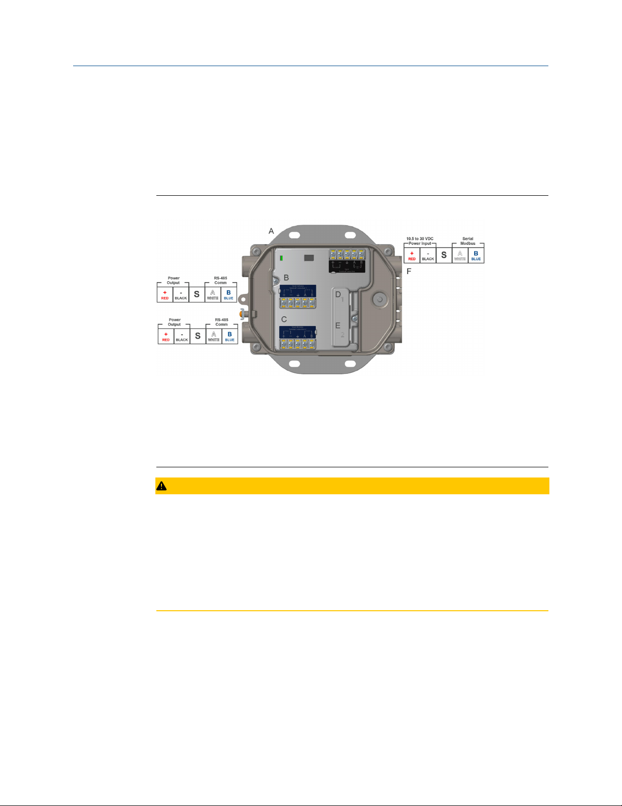
Figure 2-1: Emerson 1410S Gateway Wiring
A. Mounting plate
B. Emerson Wireless 781S Smart Antenna terminal 1 power and data connections
C. Emerson Wireless 781S Smart Antenna terminal 2 power and data connections
D. Ethernet port 1. When this port is activated, the factory IP address is 192.168.1.10.
E. Ethernet port 2. When this port is activated, the factory IP address is 192.168.2.10.
F. Emerson 1410S power and serial connections
CAUTION
Equipment damage
Connecting through the open terminal block cover may stress the connections and
damage the Gateway.
When making physical connections to the Gateway, the installer should route wire for the
Emerson 781S units through the left side entries using a separate entry for each. Power,
Ethernet, and serial Modbus® wiring should be routed through the right side wiring
entries.
2.3.1 Establishing a connection
Connect the PC/laptop to the Ethernet 1 (Primary) receptacle on the Gateway using an
Ethernet cable. This process will only need to be done once for the two networks. The
networks have the same IP address even if you are running two separate networks.
8 Emerson.com
Page 9
Reference Manual Configuration
00809-0600-4410 September 2020
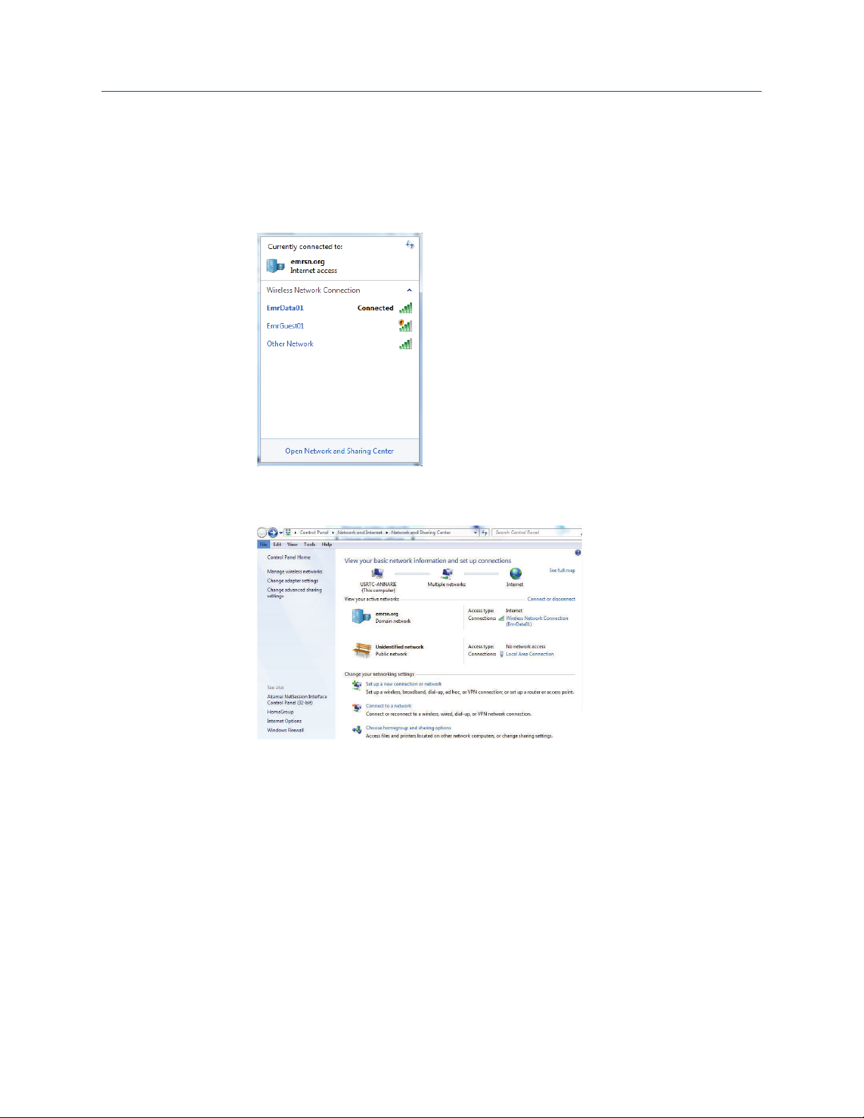
2.3.2 Windows 7
Procedure
1. Click the Internet Access icon on the bottom right of the screen.
2. Select the Network and Sharing Center.
3. Select Local Area Connection.
4. Select Properties.
5. Select Internet Protocol Version 4 (TCP/IPv4) → Properties.
Emerson 1410S/781S 9
Page 10
Configuration Reference Manual
September 2020 00809-0600-4410
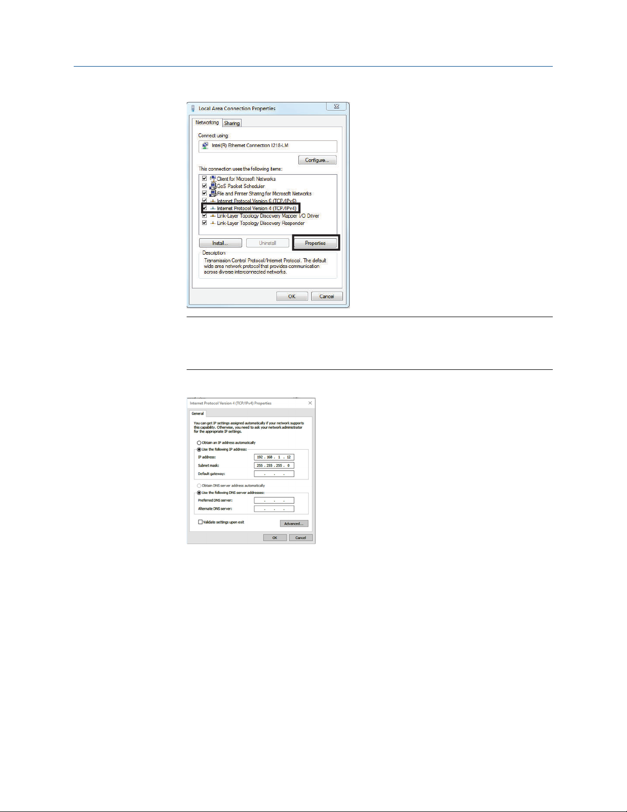
Note
If the PC/laptop is from another network, record the current IP address and other
settings so the PC/laptop can be returned to the original network after the Gateway
has been configured.
2.3.3
6. Select the Use the following IP address button.
7. In the IP address field, enter 192.168.1.12 (DeltaV Ready enter 10.5.255.12).
8. In the Subnet mask field, enter 255.255.255.0.
9. Select OK for both the Internet Protocol (TCP/IP) Properties window and the Local Area
Connection Properties window.
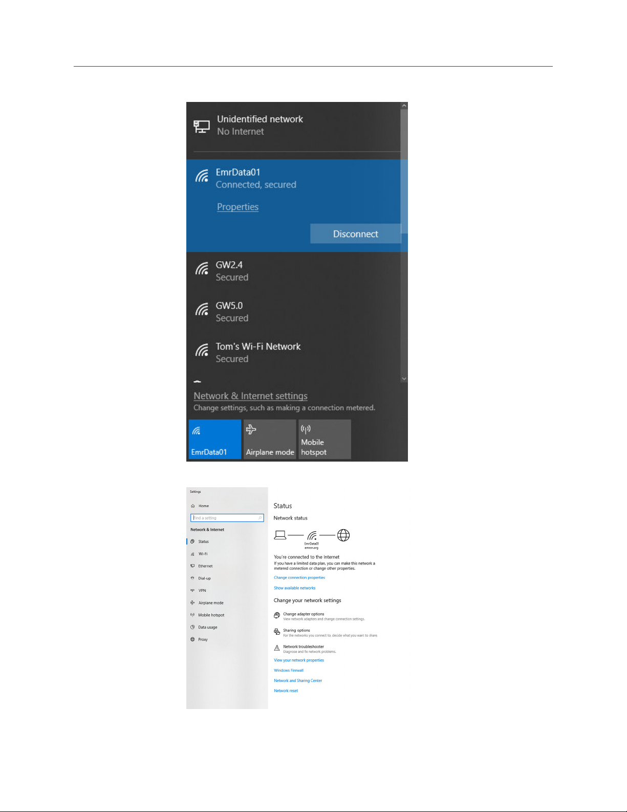
Windows 10
Procedure
1. Select the network icon in the lower right corner.
2. Select the Network settings link.
10 Emerson.com
Page 11
Reference Manual Configuration
00809-0600-4410 September 2020
3. Select Change adapter options.
Emerson 1410S/781S 11
Page 12
Configuration Reference Manual
September 2020 00809-0600-4410
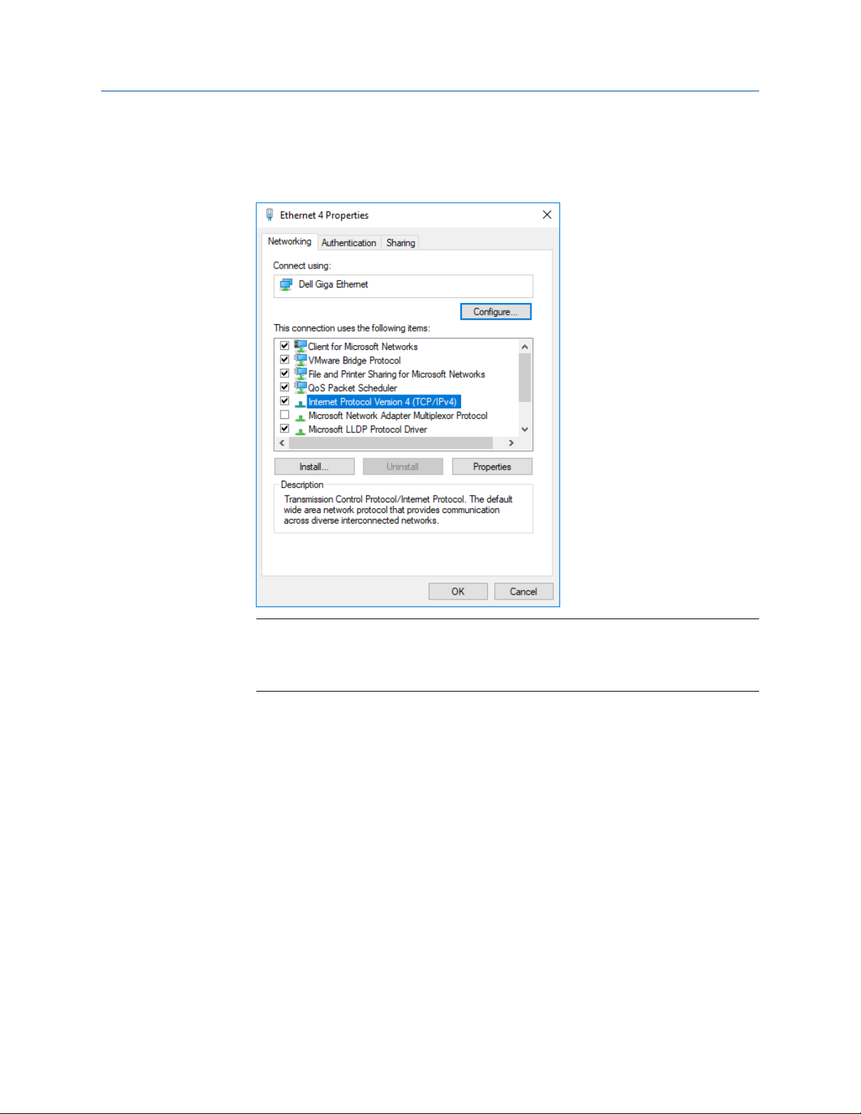
4. Right click the network interface connection that the Gateway is plugged into, and
select Properties.
5. Select Internet Protocol Version 4 (TCP/IPv4) → Properties.
Note
If the PC/laptop is from another network, record the current IP address and other
settings so the PC/laptop can be returned to the original network after the Gateway
has been configured.
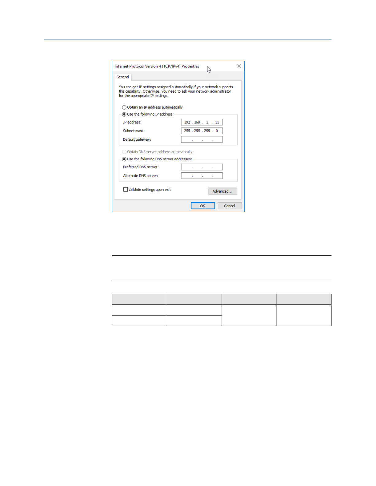
6. Select the Use the following IP address button.
12 Emerson.com
Page 13
Reference Manual Configuration
00809-0600-4410 September 2020
7. In the IP address field, enter 192.168.1.11 (DeltaV Ready enter 10.5.255.12).
8. In the Subnet mask field, enter 255.255.255.0.
9. Select OK for both the Internet Protocol (TCP/IP) Properties window and the Local Area
Connection Properties window.
Note
Connecting to the Gateway's secondary Ethernet port will require different network
settings.
Table 2-1: Network Settings
Ethernet Gateway PC/laptop/tablet Subnet
1 192.168.1.10 192.168.1.11 255.255.255.0
2 192.168.2.10
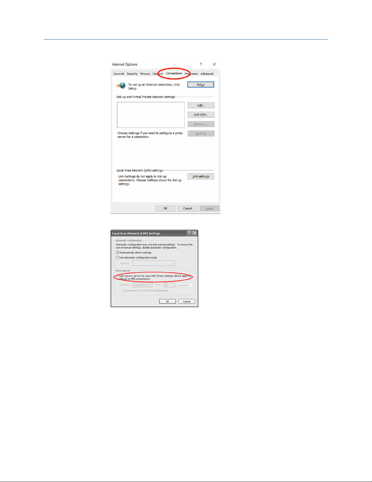
2.3.4 Disable proxies
Use these steps to disable proxies.
Procedure
1. Open web browser.
2. Navigate to Tools → Internet Options → Connections → LAN Settings (may be a
different process for other browsers).
Emerson 1410S/781S 13
Page 14
Configuration Reference Manual
September 2020 00809-0600-4410
2.3.5
3. Under Proxy server, uncheck the Use a proxy server... box.
Configure the Gateway
Use these steps to complete the initial configuration for the Gateway. This will need to be
done for both the WirelessHART® and ISA100 networks.
Procedure
1. Access the WirelessHART default web page for the Gateway at https://
192.168.1.10. You will have to configure both networks individually.
a) Log on as Username: admin
b) Type in password: default
14 Emerson.com
Page 15
Reference Manual Configuration
00809-0600-4410 September 2020
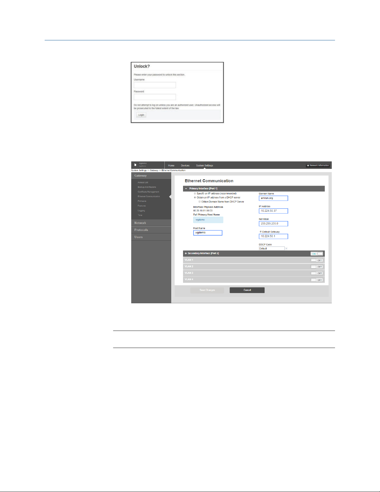
2. Navigate to System Settings → Gateway → Ethernet Communication to enter the
network settings.
a) Configure a static IP Address or set for DHCP and enter a Hostname.
b) If not prompted, restart application at System Settings → Gateway →
Backup and Restore → Restart Apps.
Note
Resetting applications will temporarily disable communications with field devices.
2.3.6
Emerson 1410S/781S 15
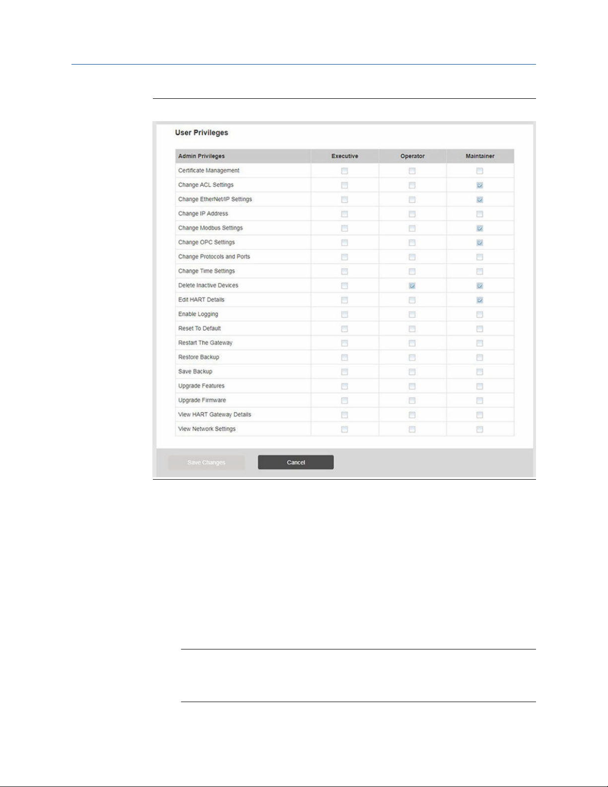
User accounts
There are four role-based user accounts for the Gateway with varying levels of access. The
access can be changed on the System Settings → Users → User Accounts by the admin
user. The figure below displays this access.
Page 16
Configuration Reference Manual
September 2020 00809-0600-4410
Figure 2-2: User Privileges
2.3.7 Change passwords
It is a secure practice to change the user account passwords from the default ones. This
should be done on both the WirelessHART and ISA100 networks. To change the User
Account passwords, follow the steps below.
Procedure
1. Navigate to System Settings → Users → User Accounts.
2. Click the Edit button of the user password to be changed.
3. Set the new password for the role based account, and confirm.
4. Select Save Changes.
Note
It is suggested the default security settings in System Settings → Users → User
Options be changed to the local IT best practices or the “Normal” setting after
initial login. Strong or custom settings are available for more robust passwords.
16 Emerson.com
Page 17
Reference Manual Configuration
00809-0600-4410 September 2020
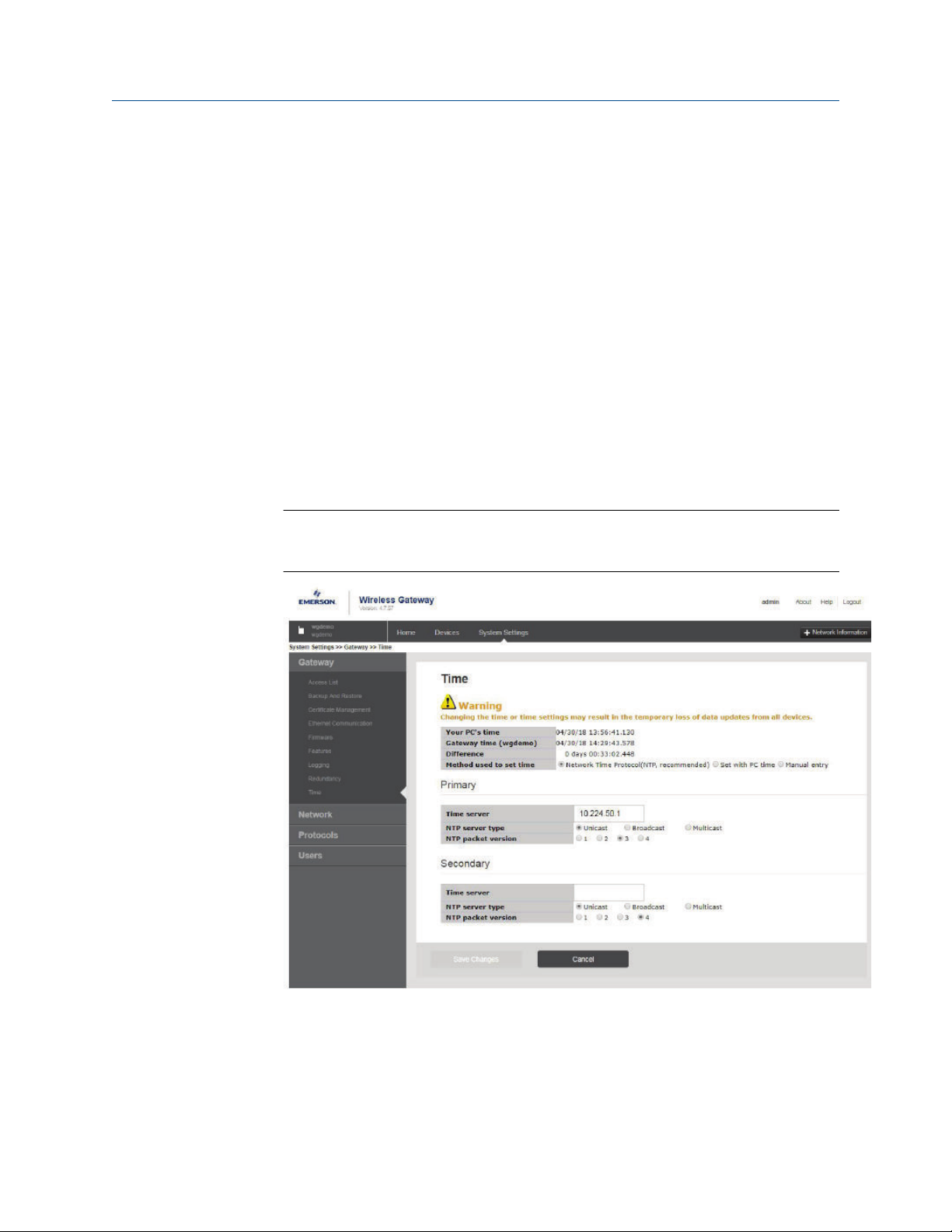
2.3.8 Time settings
The Gateway is the timekeeper for the WirelessHART® network, so it is imperative that the
Gateway’s time is accurate for timestamp data to be meaningful. Time settings can be
found by navigating to System Settings → Gateway → Time as shown in Windows 7. Any
changes made to the time settings will have to be done to both networks for consistency.
There are three ways to set the Gateway time:
Procedure
1. Network Time Protocol (recommended). This option uses a Network Time Protocol
(NTP) server to adjust the Gateway’s time to match the time of the control network.
a) Enter the IP address for the NTP server.
b) Select the packet version (i.e. 1, 2, 3, or 4).
2. Set with PC Time. This option will match the Gateway’s time to the PC/Laptop.
3. Manual Entry. This option allows the user to enter a specific date (MM:DD:YY) and
time (HH:MM:SS).
Note
Network Time Protocol (NTP) is recommended for the best network performance
because it always adjusts time to match the network time server.
2.3.9
Emerson 1410S/781S 17
To change the TCP/IP network settings
Procedure
1. Navigate to System Settings → Gateway → Ethernet Communication.
Page 18

Configuration Reference Manual
September 2020 00809-0600-4410
2. Select Specify an IP address (recommended).
3. Enter the following:
• Hostname
• Domain name
• IP Address
• Netmask
• Gateway
4. Select Save Changes.
5. When prompted, select Restart Apps.
6. Select Yes to confirm restart.
7. Close the web browser.
Note
Once the IP Address of the Gateway has been changed, communications to the web
interface will be lost. Restart the web browser, then log back into the Gateway using
the new IP address and other TCP/IP network settings. The PC/Laptop TCP/IP
network settings may need to be changed. During a restart, the wireless network
will be temporarily lost.
2.3.10
System backup
The Gateway has a System Backup and Restore feature that saves all user-configured data.
It is best practice that a System Backup be performed periodically throughout the
installation and configuration process. Starting with firmware version 4.7.53, a passphrase
is required when taking a backup. The passphrase is used to encrypt and decrypt the
backup. This will need to be done two times, for both theWirelessHART® and ISA100
networks.
Procedure
1. Navigate to System Settings → Gateway → Backup and Restore.
2. Enter a passphrase, confirm, and select Save Backup.
The Gateway collects the configuration date.
3. When the file download pop up appears, select Save.
4. Enter a save location and file name.
5. Select Save.
6. Select Return to form.
Note
System Backup contains user passwords and keys used for encrypting
communication. Store downloaded system backups in a secure location. The actual
files are also encrypted.
18 Emerson.com
Page 19

Reference Manual Configuration
00809-0600-4410 September 2020
2.3.11 Web page usage
It is not recommended that users stay logged on to a single page or a large number of
users on multiple pages for long periods of time. This additional loading can slow the flow
of data. By default, the Gateway logs users out after a long period of time with no activity.
2.3.12 Resetting to factory defaults
If the user name, password, or IP address of the Gateway is lost, the Gateway can be
restored to factory defaults using the procedure below.
Note
Following this procedure will cause the network to reform and all configuration
parameters will be reset to factory defaults. Once the Gateway is reset, the user is strongly
recommended to change the default password to maintain system security.
Procedure
1. Turn off power to the Gateway.
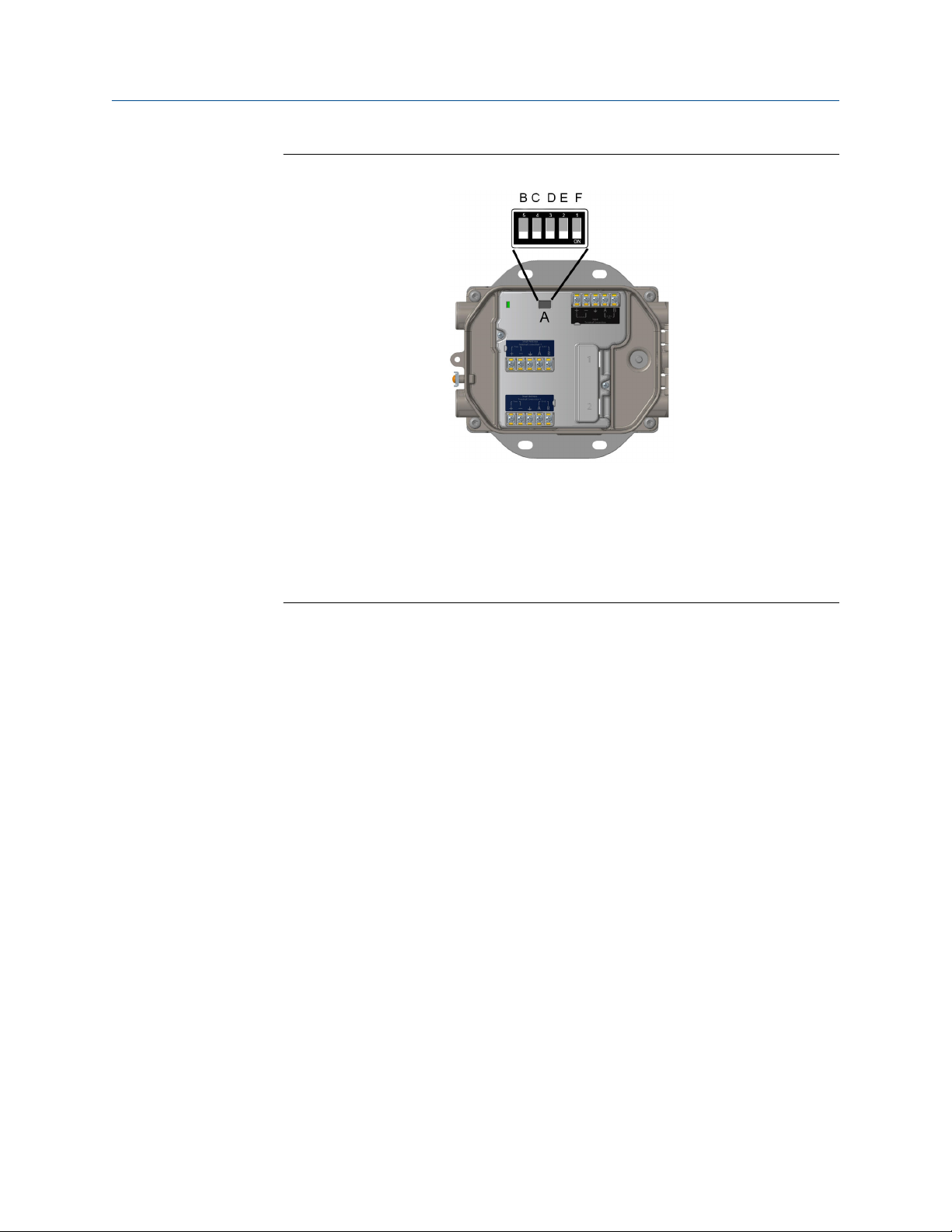
2. Locate the Reset switch.
For the Emerson 1410S2 modular housing, the switch is located inside the Gateway
housing cover on the DIP switch panel board. The reset switch is labeled switch 4.
3. Slide the switch to the “ON” position.
4. Reconnect the Gateway; turn power on to the Gateway.
5. Let the Gateway completely boot up (approximately three minutes).
During this time, the red reset light on the front of the unit will be on.
6. Turn off power to the Gateway again.
7. Return the Reset switch to the "OFF" position.
8. Mount and reconnect the Gateway; restore power to the Gateway.
9. Verify the Reset switch is in the “OFF” position.
The Gateway will now be programmed back to factory defaults including IP
addresses. See Initial connection: Web browser returns "page not found" for factory
default IP addresses.
Emerson 1410S/781S 19
Page 20
Configuration Reference Manual
September 2020 00809-0600-4410
Figure 2-3: DIP Switch Identification
A. DIP switches
B. PoE disabled
C. Reset to defaults
D. 1.5 kΩ pull-down resistor
E. 120 Ω terminating resistor
F. 1.5 kΩ pull-up resistor
20 Emerson.com
Page 21

Reference Manual Installing the Gateway
00809-0600-4410 September 2020
3 Installing the Gateway
3.1 Emerson Gateway 1410S2 installation overview
This section describes how to properly mount the Emerson 1410S2 Gateway and make
electrical connections including wiring, grounding, and host system connections.
General considerations
• The Gateway may be mounted in any general-purpose location.
• Ensure gasket between the Gateway cover and housing is in place and undamaged.
• Ensure cover is secured tightly to prevent exposure of any electronics to moisture and
contamination.
• Ensure cover is secured tightly and all used and unused wiring entries are sealed to
prevent exposure of electronics to any moisture or contamination.
• The Gateway should be mounted in a location that allows convenient access to the
host system network (process control network).
• Best practice is to install the Emerson 781S Smart Antennas centrally in the wireless
network for the most direct connections to the Gateway.
Physical description
For dimensional drawing information refer to Appendix A. The rugged modular
Emerson1410S2 Gateway electronics are enclosed in an aluminum housing. The conduit
entries in the enclosure have connections for power, Ethernet, serial and Emerson 781S
communications. The unit is designed to be modular and mountable to a pole or the
Cisco® IW6300 Access Point.
3.2 Power specifications
Table 3-1: Emerson 1410S Gateway Power
Gateway version Non-barrier Barrier
Input voltage 10.5 to 30V VDC 24 VDC
Power consumption 5 Watts 7.5 Watts
At start-up, the power supply must be capable of momentarily
sourcing at least twice the operating current. The Gateway may
draw significantly more current momentarily at start-up if not
limited by the power supply.
Power over Ethernet (PoE) Gateway supports IEEE 802.11 PoE as a Powered Device (PD) on
either port.
Emerson 1410S/781S 21
Page 22

Installing the Gateway Reference Manual
September 2020 00809-0600-4410
Table 3-1: Emerson 1410S Gateway Power (continued)
Gateway version Non-barrier Barrier
Input and output connections In: DC power (2-wire, 1 connection)
Out: DC Power (2-wire, 2 connections)
I/O: RS-485 (2-wire, 2 connections)
The Gateway is designed to be powered by 24 VDC (nominal) Class 2 supply and requires
350 mA of current.
The wiring should include an external power shut-off switch or circuit breaker positioned
near the Gateway.
The terminals on this connector can accommodate wires from 24 AWG to 12 AWG; 18
AWG wire is recommended. Tighten screws to 4.4 to 5.3 l bf-in (0.5 to 0.6 Nm).
In ambient temperatures greater than +60 °C, use wire rated for at least 5 °C above the
maximum ambient temperature.
Note
Using an uninterruptible power supply (UPS) is recommended to ensure availability during
power failure.
NOTICE
The Emerson 781S was designed for use with the Emerson 1410S Gateway and should
only be connected to the Emerson 1410S and/or other Emerson Gateway products.
Table 3-2: Emerson 781S Smart Antenna Power
Emerson Smart Antenna
model version
Input voltage
Power consumption
Radio protocol
EIRP (Max)
Antenna options
Input and output connections
781SA 781SC
10.5 to 30V VDC
0.25 W 0.30 W
IEC 62591 (WirelessHART®) IEC 62734 (ISA100)
Meets all industrial environment requirements of EN61326.
Maximum deviation less than one percent span during EMC
disturbance.
Integrated omni-directional antenna
In: DC power (2-wire)
I/O: RS-485 (2-wire)
3.3 Mounting the Emerson 1410S2 Gateway
Find a location where the Gateway has convenient access to the host system network
(process control network).
22 Emerson.com
Page 23

Reference Manual Installing the Gateway
00809-0600-4410 September 2020
3.3.1 Pipe mount
Pipe mount
The following hardware and tools are needed to mount the Gateway to a 2-in. pipe:
• Two 5/16-in. u-bolts (supplied with Gateway)
• 2-in. mounting pipe
• ½-in. socket-head wrench
1. Secure the u-bolt around the pole at the appropriate height you want the Gateway
to be secured.
2. Using a ½-in. socket-head wrench, secure the Gateway to the pole with two u-bolt
assemblies and four 15/16-in. nuts.
Figure 3-1: Pipe Mount
3.3.2
Emerson 1410S/781S 23
Bracket mount
The following hardware and tools are needed to mount the Gateway to a support bracket:
Prerequisites
• Four 15/16-in. bolts
• Mounting support bracket
• ⅜-in. drill
• ½ -in. socket-head wrench
Mount the Gateway using the following procedure:
Page 24

Installing the Gateway Reference Manual
September 2020 00809-0600-4410
Procedure
1. Drill four 3/8-in. (9,525 mm) holes spaced 3.06-in. (77 mm) apart horizontally and
11.15-in. (283 mm) apart vertically in the support bracket, corresponding with the
holes on the Gateway mounting bracket.
2. Using a 1/2-in. socket-head wrench, attach the Gateway to the support bracket with
four 15/16-in. bolts.
3.4 Mounting the Emerson 781S Smart Antenna
Intended use
The Smart Antenna must be used in conjunction with a network manager or network
Gateway. The Smart Antenna then functions as a translator between the wired network
and a wireless field network. Figure 3-2 shows one of the networks being used.
Figure 3-2: System Architecture Example
Mounting location
The Emerson Smart Antenna should be mounted in a location that allows convenient
access to the host system network (wireless I/O) as well as the wireless field device
network. Find a location where the Smart Antenna has optimal wireless performance.
Ideally this will be 15 - 25 ft. (4,6 - 7,6 m) above the ground or 6 ft. (2 m) above
obstructions or major infrastructure. If the Gateway is using two Emerson 781S Smart
Antennas, they do not need to be installed near each other. There should be at least 3 ft.
(1m) of separation between the two.
24 Emerson.com
Page 25

Reference Manual Installing the Gateway
00809-0600-4410 September 2020
Figure 3-3: Mounting Location
A. Control room
B. RS-485 cable
C. Smart Antenna
D. Mast or pipe
E. Infrastructure
3.4.1
3.4.2
Emerson Smart Antenna pipe mount
Procedure
1. Insert U-bolt around 2-in. pipe/mast, through the saddle, through the L-shaped
bracket, and through the washer plate.
2. Use a ½-in. socket-head wrench to fasten the nuts to the U-bolt.
3. Insert single bolt through L-shaped bracket into the antenna.
4. Use a 5/16 socket-head wrench to fasten bolt to bracket.
Antenna position
The Emerson 781S Smart Antenna is an omni-directional antenna that does not require
specific horizontal positioning for optimal network connectivity. It should be mounted
vertically upright in the center of the network for the most direct device connections to
the Gateway.
3.5 Connecting the Emerson 1410S to the 781S Smart Antennas
There are two main connection configurations for the Emerson 1410S and 781S Smart
Antennas: with and without intrinsically safe barriers. The hazardous location approval
option of the Emerson 781S determines whether it needs to be installed with barriers. This
connection is integrated in the Gateway electronics and can be selected upon order.
Selecting the IS barrier option will provide IS barriers integrated into the Gateway. This will
Emerson 1410S/781S 25
Page 26

Installing the Gateway Reference Manual
September 2020 00809-0600-4410
provide intrinsic safety and approval for Emerson 781S installation in Div 1/Zone 0 areas.
For more information on product approvals, see Reference data.
The Gateway enclosure acts as a junction box for wiring connections. The enclosure has
five conduit entries for power and communications wiring. Do not run communication
near heavy electrical equipment.
Install the included conduit plugs in any unused conduit openings. For NEMA® 4X and IP65
requirements, use thread seal (PTFE) tape or paste on male threads to provide a watertight
seal.
3.5.1 Emerson 1410S grounding
The DIN-rail mounted Emerson 1410S1 Gateway does not require an external ground
because the back DIN mounting plate is already grounded.
The rugged modular Emerson 1410S2 Gateway enclosure case should always be grounded
in accordance with national and local electrical codes. The most effective grounding
method is a direct connection to earth ground with minimal impedance. Ground the
Gateway by connecting the external grounding lug to earth ground. The connection
should be 1Ω or less. The external ground plug is located on the left side of the Gateway
enclosure and is identified by the following symbol:
3.5.2
Ethernet
The Gateway is equipped with two 10/100BaseTX Ethernet communications ports (see
Emerson 781S installation). These connections can be used to access the Gateway’s web
interface and to communicate using other available protocols.
The primary Ethernet port (Ethernet 1) is used to connect to the host system or other
application systems. The secondary Ethernet port (Ethernet 2) can be used as a backup
connection or a maintenance port for local access to the Gateway.
26 Emerson.com
Page 27

Reference Manual Installing the Gateway
00809-0600-4410 September 2020
3.5.3 Emerson 781S installation
A shielded twisted-pair cable is needed for connecting the Emerson 1410S and each 781S
Smart Antennas. Each antenna can be located up to 1312 ft. (400m) from the Gateway.
Figure 3-4: Emerson 1410S Gateway and Single 781S Smart Antenna
A. Emerson Wireless 1410S Gateway
B. Attach shield pair cable (Belden 3084A or equivalent)
Tape back shield wire and foils if connecting through a junction box between the
Emerson 781S and 1410S Gateway.
C. Emerson Wireless 781S Smart Antenna
Figure 3-5: Emerson 1410S Gateway and Two 781S Smart Antennas
A. Emerson WirelessHART® 781S Smart Antenna
B. Attach shield pair cable (Belden 3084A or equivalent)
C. Optional secondary Emerson Wireless 781S Smart Antenna
D. Tape back shield wire and foils
E. Emerson Wireless 1410S Gateway
Emerson 1410S/781S 27
Page 28

Tx
Rx
Tx
Rx
(A)
(B)
Installing the Gateway Reference Manual
September 2020 00809-0600-4410
3.5.4 RS-485
The Gateway can be ordered with an optional RS-485 (serial) connection (see Figure 3-4).
Modbus® terminals are labeled A and B on the wiring diagram. This connection is used to
communicate Modbus RTU on an RS-485 data bus.
Use 18 AWG single twisted shielded pair wiring to connect the Gateway to the RS-485 data
bus. The total bus length should not exceed 4000 ft. (1220 m). Connect the Tx - (negative,
receive) wire to terminal A and the Rx + (positive, transmit) wire to terminal B. The wiring
shield should be trimmed close and insulated from touching the Gateway enclosure or
other terminations.
If the existing data bus uses a 4-wire Full Duplex configuration, see Figure 3-6 to convert to
a 2-wire Half Duplex configuration.
Figure 3-6: Convert from Full to Half Duplex
3.5.5
3.5.6
Shield grounding
The shields of the twisted-pair cables need to be grounded using the grounding terminal
on the Emerson 1410S.
Terminating resistors
Three of the five DIP switches are provided to enable various terminating and biasing
resistors to the RS-485 (Modbus®) data bus. The switches are found inside the electronics
housing, located in the square opening of the shroud on the upper left side (Figure 3-7).
The switches number left to right going down from 5 to 1. The downward position on the
switch is ON.
Three DIP switches are provided to enable various terminating resistors to the RS-485 data
bus. The terminating resistor on the Emerson 781S connection (120 ohm) is always
enabled.
28 Emerson.com
Page 29

Reference Manual Installing the Gateway
00809-0600-4410 September 2020
Figure 3-7: DIP Switch Identification
3.5.7
A. DIP switches
B. PoE disabled
C. Reset to defaults
D. 1.5 kΩ pull-down resistor
E. 120 Ω terminating resistor
F. 1.5 kΩ pull-up resistor
Switches 1 and 3 are connected to pull-up and pull-down resistors for Modbus connection.
Switch 1 is for the Tx + (A) line and Switch 3 is for the Rx – (B) line. These 1.5 kΩ resistors
are used to prevent noise from being interpreted as valid communications during periods
when no actual communications are occurring. Only one set of pull-up and pull-down
resistors should be active on the RS-485 data bus at time.
Switch 2 is connected to a 120 Ω terminating resistor for Modbus connection. This resistor
is used to dampen signal reflections on long cable runs. RS-485 specifications indicate that
the data bus should be terminated at both ends (Figure 3-7).
Power over Ethernet (PoE)
This Gateway is equipped with PoE technology to derive its power from another PoE
device via the Ethernet connection (PD mode). This device complies with the IEEE
802.3af-2003 or IEEE 802.3at -2009 for PD operation.
These standards require the use of Category 5 Ethernet cable or higher. In the operation of
IEEE 802.3a, PoE power is only transmitted from one device to another when the proper
impedance match is made. This prevents damage to non PoE devices on the network.
Emerson 1410S/781S 29
Page 30

Installing the Gateway Reference Manual
September 2020 00809-0600-4410
To use this feature, the Gateway must be connected over the Ethernet to a matching IEEE
802.3a device. Failure to do this will cause no power sourced. A switch on the power
supply board allows a PD (Powered Device) to be enabled or disabled.
PoE advantages
To save costs on planning, wiring and installation of networks, devices are supplied with
power directly via the Ethernet cable (e.g. via a Cat 5/5e cable up to 100m). PoE makes the
network planning flexible, independent of power supply cabinets, and junction boxes.
There are no extra costs for the electrical wiring. An advantage of PoE is that you can install
devices with an Ethernet interface in places of difficult access or in areas in which running
cable would be inconvenient. This in turn saves installation time and costs. This
technology is in use today typically in IP telephones, cameras, or wireless transmission
devices such as WLAN Access Points.
An excellent application is a Gateway connected to a Wi-Fi back haul unit; such as a Cisco
®
unit. For example, a Cisco IW6300 unit could power the Gateway over a PoE connection.
Selecting devices to work with a PoE Gateway
When connecting the Gateway to a PSE device, it must be labeled as compliant with IEEE
802.3af or IEEE 802.3at. Many companies use labels on their packaging such as PoE for
IEEE 802.3af or PoE+ for IEEE 802.3at. Check the specific manufacturer's specifications of
any device to make sure somewhere it references IEEE 802.3; otherwise it may not work.
Caution is needed in selecting a companion device to the Gateway for PoE. Not all devices
labeled PoE will function. Before 2003, there was no standard and companies developed
their own techniques for powering over an Ethernet cable. These techniques are not
always interoperable. Before the standard, they used the term PoE on many of their
products. Most new products labeled PoE are IEEE compatible. Cisco products can be
ordered with their old standard (Online Power as it is sometimes referred to) or with the
IEEE 802.3 PoE standard. Check with the appropriate manufacturer if in doubt before
purchasing/installing the connecting equipment.
For reference, Cisco offers the following four versions:
1. Pre standard PoE (Online Power)
2. 802.3af-compliant PoE (15W)
3. 802.3at-compliant PoE Plus (PoE+) (25W)
4. Universal PoE (UPoE) (60W). (New Cisco standard, which Cisco claims is compatible
with IEEE 802.3af PoE and IEEE 802.3at PoE +)
30 Emerson.com
Page 31

Reference Manual Installing the Gateway
00809-0600-4410 September 2020
NOTICE
IEEE 802.3 PoE gives protection from damaging a computer or another piece of
equipment
When using IEEE 802.3 PoE, one of the important new features of this standard is that PSE
devices have a test mechanism to protect connected incompatible devices from being
damaged. Only devices which have an authenticating characteristic based on the IEEE
802.3 standard, receive power via the Ethernet cable. To determine whether a PD is
connected, the input parameters are checked by the PSE. This method is called “Resistive
Power Discovery”. During the discovery process resistance, capacitance, and current are
checked
If the PSE detects a PD, it starts classification (i.e. determination of the power requirement
of the connected device). The PSE applies a small defined voltage to the power input of the
PD's and measures the resulting current. The PD is assigned to a power class based on the
value of the current. Only now the total voltage is supplied to the power input.
This sophisticated system prevents computers and other devices from being damaged
when connected to these cables.
PoE FAQs
What do I have to
do to order IEEE PoE
on a 1410S
Gateway?
What is the
maximum Voltage
PoE PSE can source?
Can you do
redundant power
with PoE?
There is no specific option code for PoE. All 1410S Gateways have
PoE. The only configuration needed is to flip DIP switch 5. Turning
the switch “ON” means to disable PoE.
Maximum voltage is normally 48 VDC; up to 25 Watts.
Yes, as PoE becomes more popular many network appliance
(switch) providers are supplying innovative switches and other
hardware to create redundantly powered networks. Typically,
many switch suppliers offer switches that allow multiple power
inputs. Check your local switch supplier for available
configurations. Also, the Gateway will work with a local power
supply connected to the power input terminals of the Gateway
and as a PD with power coming over the Ethernet at the same
time. If both sources are present, the Gateway selects the local
power supply first. If the local power fails, the Gateway
automatically switches to Ethernet power. When the local power
is restored, the Gateway automatically returns to local power.
3.6 Verify operations
Operation is verified through the web interface by opening a web browser from any PC on
the host system network and entering the Gateway IP address or DHCP host name in the
address bar. If the Gateway has been connected and configured properly, the security alert
will be displayed followed by the log in screen. This will need to be done to both the
WirelessHART® and ISA100 networks.
Emerson 1410S/781S 31
Page 32

Installing the Gateway Reference Manual
September 2020 00809-0600-4410
Figure 3-8: Gateway Log In Screen
The Gateway is now ready to be integrated into the host system. If wireless field devices
were ordered with the Gateway, they were preconfigured with the same Network ID and
Join Key information. Once the field devices are powered, they will appear on the wireless
network and communications can be verified under the Explore tab using the web
interface. The time needed for the network to form will depend on the number of devices.
32 Emerson.com
Page 33

Reference Manual Commissioning
00809-0600-4410 September 2020
4 Commissioning
4.1 Overview
This section discusses the installation and setup of the optional software included with the
Emerson Wireless Gateway. The following table describes what items are installed and on
which disk they can be found.
Table 4-1: Software Applications
Name Description Location
Security Setup
Utility
AMS Wireless
Configurator
Network
Configuration
Additional system components may be installed depending on the current configuration
of the system.
This utility allows the setup of SSL enabled communications
between the Gateway and host system.
This application allows complete configuration of wireless field
devices and provides added security through drag and drop
provisioning.
This application configures AMS Wireless Configurator to
interface to a wireless network or a HART® Modem.
4.2 System requirements
Table 4-2: PC Hardware
Minimum requirements Recommended requirements
Intel® Core 2 Duo, 2.0 GHz Intel Core 2 Quad, 2.0 GHz or greater
1 GB Memory 3 GB Memory or Greater
1.5 GB free hard disk space 2 GB or more of free hard disk space
Note
Additional hard disk space is required for SNAP-ON™ applications. The minimum monitor
requirements are 1024 × 768 resolution and 16-bit color.
Disk 1
Disk 2
Disk 2
Table 4-3: Supported Operating Systems
Operating system Version
Microsoft® Windows™ XP Professional, Service Pack 3
Windows Server 2003 Standard, Service Pack 2
Windows Server 2003 R2 Standard, Service Pack 2
Windows Server 2008 Standard, Service Pack 2
Windows Server 2008 R2 Standard, Service Pack 1
Windows 7 Professional, Service Pack 1
Emerson 1410S/781S 33
Page 34

Commissioning Reference Manual
September 2020 00809-0600-4410
Table 4-3: Supported Operating Systems (continued)
Operating system Version
Windows 7 Enterprise, Service Pack 1
Windows 8 Enterprise, Service Pack 1
Windows Server 2008 Standard, Service Pack 2
Windows 10 Enterprise, Service Pack 1
Note
Only 32-bit versions of the operating systems are supported for AMS Wireless
Configurator.
4.3 Software installation
The software can be found on the two-disk pack, included with the Gateway. Depending
on the PC system configuration, installation may take 30-35 minutes. Installing disk one
followed by disk two is recommended. The Security Setup Utility is located on disk 1.
Procedure
1. Exit/close all Microsoft® Windows™ programs, including any running in the
background, such as virus scan software.
2. Insert disk 1 into the CD/DVD drive of the PC.
3. Follow the prompts.
AMS Wireless Configurator is located on disk 2. To install the software:
4. Exit/close all Windows programs, including any running in the background, such as
virus scan software.
5. Insert disk 2 into the CD/DVD drive of the PC.
6. Select Install from the menu when the AMS Wireless Configurator setup begins.
7. Follow the prompts.
8. Allow AMS Wireless Configurator to reboot PC.
9. Do not remove the disk from the CD/DVD drive.
10. Installation will resume automatically after login.
11. Follow the prompts.
Note
If the autorun function is disabled on the PC, or installation does not begin automatically,
double click D:\SETUP.EXE (where D is the CD/DVD drive on the PC) and select OK.
4.4 Security setup utility
The Security Setup Utility enables secure communications between the Gateway and host
system, asset management software, data historians, or other applications. This is done by
encrypting the standard data protocols (AMS Wireless Configurator, Modbus® TCP, and
OPC) used by the Gateway and making them available through various proxies within the
34 Emerson.com
Page 35

Reference Manual Commissioning
00809-0600-4410 September 2020
Security Setup Utility. These proxies can function as a data server for other applications on
the control network. The Security Setup Utility can support multiple Gateways at once and
each proxy can support multiple client application connects. Figure 4-1 shows a typical
system architecture using the Security Setup Utility.
Figure 4-1: Typical Host System Architecture Using Security Setup
A. Data server
B. Engineering station
C. Asset management
D. Historian
E. Security setup utility
F. AMS proxy
G. Modbus proxy
H. OPC proxy
I. Control network
J. Encrypted data
Note
OPC communications requires the use of the Security Setup Utility regardless of whether
encryption is required.
4.5 AMS Wireless Configurator
AMS Wireless Configurator helps deploy and configure wireless field devices. It provides an
HART® integrated operating environment that leverages the full capabilities of
WirelessHART®, including embedded data trending, charting, and graphical display
capabilities provided by enhanced EDDL technology.
• Display and modify device configuration
• View device diagnostics
Emerson 1410S/781S 35
Page 36

Commissioning Reference Manual
September 2020 00809-0600-4410
• View process variables
• Provision a wireless device using the drag-and-drop operation so it can join a Gateway’s
self-organizing network
• Enhance AMS Wireless Configurator functionality with the AMS Wireless SNAP-ON
Application
• Restrict access to AMS Wireless Configurator functions through the use of security
permissions
See the release notes for information specific to the current release of AMS Wireless
Configurator. To display the release notes, navigate to Start → Programs → AMS
Wireless Configurator → Help.
™
4.6 Licensing and credits
The latest licensing agreements are included on each disk of the software pack.
This product includes software developed by the OpenSSL Project for use in the OpenSSL
Toolkit.
36 Emerson.com
Page 37

Reference Manual Operation and maintenance
00809-0600-4410 September 2020
5 Operation and maintenance
5.1 Overview
This section describes how to connect the Gateway to a host system and integrate data
gathered from the field device network. It covers network architectures, security, and data
mapping.
5.2 Network architecture
Physical connection types are important when determining the network architecture and
usable protocols for integration. Ethernet is the primary physical connection type; RS485
is also available. The following network architecture diagrams will help when integrating
data from the Gateway into the host system.
Ethernet
An Ethernet connection supports Modbus® TCP, OPC, AMS Wireless Configurator,
EtherNet/IP,™ and HART® TCP protocols. Using this connection type, the Gateway is wired
directly to a control network (see Figure 5-1) using a network switch, router, or hub. Often
there are two networks for redundancy purposes.
Figure 5-1: Ethernet Architecture
A. Engineering station
B. Primary control network
C. Secondary control network
D. Controller and I/O
E. Wireless Gateway
Emerson 1410S/781S 37
Page 38

Operation and maintenance Reference Manual
September 2020 00809-0600-4410
RS485 (serial)
An RS485 connection supports Modbus RTU protocol. Using this connection type, the
Gateway is wired to an RS485 bus which typically leads to a serial I/O card or Modbus I/O
card (see Figure 5-2). Up to 31 Gateways can be connected to a single I/O card in this
manner.
Figure 5-2: RS485 Architecture
A. Engineering station
B. Primary control network
C. Controller and I/O
D. Secondary control network
E. Serial I/O card
F. RS485 bus
G. Wireless Gateway
5.3 Modbus
The Gateway supports both Modbus RTU over the RS-485 serial port and Modbus TCP over
Ethernet. It functions as a sub device on the Modbus network and must be polled by a
Modbus master or client (host system).
Communication settings
It is import that the Modbus communication settings in the Gateway match the settings in
the Modbus master or client. Please refer to host system documentation for more
information on how to configure these settings. The Modbus communication settings can
be found by navigating to System Settings → Protocols → Modbus.
®
38 Emerson.com
Page 39

Reference Manual Operation and maintenance
00809-0600-4410 September 2020
Figure 5-3: Modbus Communications Page
Single Modbus
Address
Multiple Modbus
Addresses
Modbus TCP Port
When selected, this address is used by the Gateway for Modbus
RTU communications.
When selected, a new address column will appear on the
Modbus mapping page.
This is the TCP/IP port the Gateway uses for Modbus TCP
(Ethernet). To change TCP/IP port settings, see the Internal
Firewall section for more details.
Baud Rate
The data rate or speed of serial communications. This setting is
only required for Modbus RTU.
Parity
This setting determines parity (none, even, or odd) used for error
checking purposes. This setting is only required for Modbus RTU.
Stop Bits
This setting determines the number (1 or 2) of stop bits used
when ending a message. This setting is only required for Modbus
RTU.
Emerson 1410S/781S 39
Page 40

Operation and maintenance Reference Manual
September 2020 00809-0600-4410
Response delay time
(ms)
Unmapped register
read response?
Floating point
representation
Use swapped
floating point
format?
This setting determines how long (ms) the Gateway waits before
responding to a Modbus request. This setting is only required for
Modbus RTU.
This is the value returned by the Gateway if the Modbus master
requests a register with no data assigned to it (empty register). It
is recommended this be set to zero fill to prevent errors.
This setting determines if the Gateway uses floating point values
or integer values. There are three options for this setting.
• Float–uses 32 bit floating point values
• Round–rounds the data value to the nearest whole number
• Scaled–uses scaled integers to offset negative values or
increase decimal point resolution. The equation for scaled
integers is:
y = Ax - (B - 32768)
Where:
y = Scaled integer returned by the Gateway
A = Gain for scaled integer value
x = Measured value from wireless field device
B = Offset for scaled integer value
This setting switches which register is sent first for a floating
point value. This setting is only used for floating point values.
Incorporate value’s
associated status as
error?
Value reported for
error (floating point)
Value reported for
error (rounded and
native integer)
Scaled floating point
maximum integer
value
Use global scale gain
and offset?
This setting causes the Gateway to report a predetermined value
when a communications or critical diagnostic error is received
from the wireless field device. The value is user configurable
depending on which floating point representation is chosen. See
Value reported for error below.
This setting determines what value is reported if the wireless
field device reports a failure or stops communicating to the
Gateway. This setting is used for floating point values. The
choices are NaN (not a number), +Inf (positive infinity), -Inf
(negative infinity), or Other (user specified).
This setting determines what value is reported if the wireless
field device reports a failure or stops communicating to the
Gateway. This setting is used for rounded or scaled integers. The
choice is a user specified value between -32768 and 65535.
This determines the maximum integer value for the purpose
scaling integers. 999-65534.
This setting determines if a global gain and offset is applied for
scaled integers or if each value has a unique gain and offset.
Unique gain and offsets are found on the Modbus Mapping page.
40 Emerson.com
Page 41

Reference Manual Operation and maintenance
00809-0600-4410 September 2020
Global scale gain
Global scale offset
This value is multiplied by the data values for the purpose of
scaling integers. If global scaling is not selected, a gain value will
be available for each separate data value on the Modbus Mapping
page.
This value is added to the data values for the purpose of scaling
integers. If global scaling is not selected, an offset value will be
available for each separate data value on the Modbus Mapping
page.
Emerson 1410S/781S 41
Page 42

Operation and maintenance Reference Manual
September 2020 00809-0600-4410
42 Emerson.com
Page 43

Reference Manual Troubleshooting
00809-0600-4410 September 2020
6 Troubleshooting
6.1 Service support
This section provides basic troubleshooting tips for the Emerson Smart Wireless Field
Network. To receive technical support by phone:
Global Service Center
Software and Integration support
United States-1 800 833 8314
International-63 2 702 1111
Customer Central
Technical support, quoting, and order-related questions
United States-1 800 999 9307 (7:00 am to 7:00 pm CST)
Asia Pacific-65 6777 8211
Europe/Middle East/Africa-49 (8153) 9390
Or email the wireless specialists at: Specialists-Wireless.EPM-RTC@EmersonProcess.com
6.2 Initial connection: Web browser returns "page not found"
Possible cause: Incorrect IP address
Recommended actions
1. Connect the Gateway and PC/laptop.
2. Verify the Gateway is properly powered, 24 VDC (nominal) and 250 mA.
3. Verify the IP address for the Gateway (default primary port is 192.168.1.10,
default secondary port is 192.168.2.10 or for DeltaV™ Ready Gateway’s default
primary port is 10.5.255.254, default secondary port is 10.9.255.254).
4. Verify the IP address of the PC/laptop is in the same subnet range as the
Gateway (i.e. If the Gateway IP is 155.177.0.xxx, then the PC/Lap IP address
should be 155.177.0.yyy).
Possible cause: Internet proxy settings
Recommended actions
1. Connect the Gateway and PC/laptop.
2. Verify the Gateway is properly powered, 24 VDC (nominal) and 250 mA.
3. Disable Internet browser proxy settings.
Emerson 1410S/781S 43
Page 44

Troubleshooting Reference Manual
September 2020 00809-0600-4410
6.3 Initial connection: Cannot find Gateway after changing IP address
Possible cause: Incorrect IP address
Recommended actions
1. Verify the IP address of the PC/laptop is in the same subnet range as the
Gateway (i.e. If Gateway IP address is 155.177.0.xxx, then PC/laptop IP address
should be 155.177.0.yyy).
2. Consider resetting the gateway to factory defaults.
6.4 Initial connection: Cannot find Gateway using secondary Ethernet port
Possible cause: Incorrect IP address
Recommended actions
1. Verify which Ethernet port is being used on the Gateway.
2. Verify the Gateway IP address (default primary port is 192.168.1.10, default
secondary port is 192.168.2.10).
3. Verify the IP address of the PC/laptop is in the same subnet range as the
Gateway (i.e. If Gateway IP address is 155.177.0.xxx, then PC/laptop IP address
should be 155.177.0.yyy).
4. Verify this option was ordered with the Gateway.
6.5 Initial connection: Cannot log into the Gateway
Possible cause: Incorrect credentials
Recommended actions
1. Verify the user name and password (administrator user name is "admin", default
password is "default").
2. If unable to connect, consider resetting the Gateway.
6.6 AMS Wireless Configurator: Gateway does not appear in AMS Wireless Configurator
44 Emerson.com
Page 45

Reference Manual Troubleshooting
00809-0600-4410 September 2020
Possible cause: Wireless network interface configuration
Recommended actions
1. Verify the Security Setup Utility is installed on the same PC as AMS Wireless
Configurator.
2. Setup a wireless network interface using the Network Configuration
application.
3. Verify the wireless network interface is configured for secure Gateway
communications.
4. Verify secure/unsecure AMS Wireless Configurator protocol settings in the
Gateway.
a) Log on to the Gateway.
b) Navigate to SETUP → SECURITY → PROTOCOLS.
5. Restart AMS Wireless Configurator data server.
a) Right click on AMS Wireless Configurator server icon in the Windows
system tray (lower right corner).
b) Select Stop server.
6.7 AMS Wireless Configurator: Wireless devices do not appear under the Gateway
Possible cause: Devices not connected
Recommended actions
1. Log on to the Gateway and navigate to EXPLORER.
2. Right click on wireless network and select Rebuild hierarchy.
6.8 AMS Wireless Configurator: Wireless device appears with red HART® symbol
Possible cause: Non-current device support files
Recommended actions
1. Navigate to Emerson's AMS Device Manager product page.
2. Install latest device support files from AMS Wireless Configurator.
6.9
AMS Wireless Configurator: Device configuration items are grayed out
Emerson 1410S/781S 45
Page 46

Troubleshooting Reference Manual
September 2020 00809-0600-4410
Possible cause: Session timeout
Recommended actions
1. Verify whether current or historical information is being displayed (setting is
displayed at the bottom of each device configuration screen). Configuration
requires the Current setting.
2. Log back into AMS Wireless Configurator.
For security purposes, a configuration timeout is applied to sessions that have
been idle for more than 30 minutes.
6.10 Wireless field devices: Wireless device does not appear on the network
Recommended actions
1. Verify the device has power.
2. Verify the device is within effect communications range.
3. Verify the proper network ID has been entered into the device.
6.11 Wireless field devices: Wireless device appears in the join failure list
Recommended actions
Re-enter the network ID and join key into the device.
6.12 Wireless field devices: Wireless device appears with service denied
Possible cause: Update rate setting
Recommended actions
1. Verify the total number of devices on the network (25 maximum).
2. Go to SETUP → NETWORK → BANDWIDTH and click Analyze bandwidth.
Any changes will require the network to reform.
3. Reduce the update rate for the device.
46 Emerson.com
Page 47

Reference Manual Troubleshooting
00809-0600-4410 September 2020
6.13 Modbus communications: Cannot communicate using Modbus® RTU
Recommended actions
1. Verify the use of RS-485.
2. Verify wiring connections.
3. Verify if termination or a pull up is required.
a) Verify that Modbus serial communications settings in the Gateway
match the Modbus Host settings.
b) Log on to the Gateway and navigate to SETUP → MODBUS →
COMMUNICATIONS.
4. Verify the Modbus address for the Gateway.
5. Verify Modbus register mapping in the Gateway.
a) Log on to the Gateway and navigate to SETUP → MODBUS → MAPPING.
6.14 Modbus communications: Cannot communicate using Modbus® TCP
Possible cause: Incorrect settings
Recommended actions
1. Verify secure/unsecure Modbus protocol settings in the Gateway.
a) Log on to the Gateway.
b) Navigate to SETUP → SECURITY → PROTOCOLS.
2. Verify the Modbus TCP communications settings in the Gateway.
a) Log on to the Gateway.
b) Navigate to SETUP → MODBUS → COMMUNICATIONS.
3. Verify Modbus register mapping in the Gateway.
a) Log on to the Gateway.
b) Navigate to SETUP → MODBUS → MAPPING.
6.15 Modbus communications: Cannot communicate using secure Modbus® TCP
Emerson 1410S/781S 47
Page 48

Troubleshooting Reference Manual
September 2020 00809-0600-4410
Recommended actions
1. Verify the Security Setup Utility has been installed.
2. Configure a secure Modbus proxy for the Gateway (see Security setup utility).
3. Verify secure/unsecure Modbus protocol settings in the Gateway
a) Log on to the Gateway.
b) Navigate to SETUP → SECURITY → PROTOCOLS.
4. Verify the Modbus TCP communications settings in the Gateway.
a) Log on to the Gateway.
b) Navigate to SETUP → MODBUS → COMMUNICATIONS.
5. Verify Modbus register mapping in the Gateway.
a) Log on to the Gateway.
b) Navigate to SETUP → MODBUS → MAPPING.
6.16 OPC communications: OPC application cannot find a Gateway OPC server
Possible cause: Incorrect Security Setup Utility installation
Recommended actions
1. Verify the Security Setup Utility has been installed on the same PC as the OPC
application.
2. Configure an OPC proxy for the Gateway (see Security setup utility).
6.17 OPC communications: Gateway OPC server does not show any Gateways
Possible cause: Proxy not configured
Recommended actions
Configure an OPC proxy for the Gateway (see Security setup utility).
6.18 OPC communications: Gateway OPC server does not show any data tags
48 Emerson.com
Page 49

Reference Manual Troubleshooting
00809-0600-4410 September 2020
Possible cause: Configuration or settings
Recommended actions
1. Configure the Gateway OPC Browse Tree.
a) Log on to the Gateway.
b) Navigate to SETUP → OPC → OPC BROWSE TREE.
2. Verify the connection status for the OPC proxy in the Security Setup Utility.
3. Check to ensure the OPC proxy is configured for secure or unsecure
communications.
4. Verify secure/unsecure OPC protocol settings in the Gateway.
a) Log on to the Gateway.
b) Navigate to SETUP → SECURITY → PROTOCOLS.
5. Verify network firewall and port settings.
6.19 EtherNet/IP™: Gateway is not publishing the parameters
Possible cause: System integration
Recommended actions
1. Verify connection is established with EtherNet/IP.
a) Navigate to SETUP → SECURITY → PROTOCOLS.
2. To connect to an Allen-Bradley® system, reference the Integration Manual.
6.20 Return of materials
To expedite the return process outside of North America, contact your Emerson
representative.
Within the United States, call the Emerson Response Center toll-free number 1 800 654
7768. The center, which is available 24 hours a day, will assist you with any needed
information or materials.
The center will ask for product model and serial numbers, and will provide a Return
Material Authorization (RMA) number. The center will also ask for the process material to
which the product was last exposed.
Emerson 1410S/781S 49
Page 50

Troubleshooting Reference Manual
September 2020 00809-0600-4410
WARNING
Individuals who handle products exposed to a hazardous substance can avoid injury if they
are informed of, and understand, the hazard. If the product being returned was exposed to
a hazardous substance as defined by OSHA, a copy of the required Material Safety Data
Sheet (MSDS) for each hazardous substance identified must be included with the returned
goods.
50 Emerson.com
Page 51

Reference Manual Reference data
00809-0600-4410 September 2020
A Reference data
A.1 Ordering information, specifications, and
drawings
To view current Emerson 1410S and 781S ordering information, specifications, and
drawings, follow these steps:
Procedure
1. Navigate to the product page for Emerson 1410S and 781S.
2. Scroll as needed to the green menu bar and click Documents & Drawings.
3. For installation drawings, click Drawings & Schematics and select the appropriate
document.
4. For ordering information, specifications, and dimensional drawings, click Data
Sheets & Bulletins and select the appropriate Product Data Sheet.
A.2 Product certifications
To view current Emerson1410S and 781S product certifications, follow these steps:
Procedure
1. Navigate to the product page for Emerson 1410S and 781S.
2. Scroll as needed to the green menu bar and click Documents & Drawings.
3. Click on Manuals & Guides.
4. Select the appropriate Quick Start Guide.
Emerson 1410S/781S 51
Page 52

Reference data Reference Manual
September 2020 00809-0600-4410
52 Emerson.com
Page 53

Reference Manual Redundant Gateway systems
00809-0600-4410 September 2020
B Redundant Gateway systems
B.1 Overview
Redundancy for the Emerson Wireless 1410S Gateway increases the availability of the
wireless field network by providing two sets of physical hardware which operate as a single
Gateway system. This section covers setup and installation of a redundant Gateway
system. It also covers diagnostics and integration to help monitor the health of the
redundant Gateway system.
• Where to mount the respective antennas
• Illustration of maximum redundancy including dual switch and UPS
• Understanding how the fail over works and experience to expect
• How to leverage the multimaster capability for Modbus® integrations
B.2 Requirements
Wireless Gateway
• Firmware version 4.3.19 or greater is recommended
• RD option for Gateway redundancy
• Static IP address
• Must have matching output protocols (e.g. Modbus® or OPC®) on each Gateway
Host system
• Ethernet connection for Modbus TCP or OPC DA communications
• Serial (RS-485) connection for Modbus RTU communications
B.3 Setup
When configuring redundant Gateways, it is only necessary to configure one system. The
other Gateway will be configured automatically when it is paired with the first Gateway.
Choose one Gateway as the starter Gateway. For the purposes of this document, it will be
referred to as Gateway A. The other Gateway will be referred to as Gateway B.
To configure redundancy system settings:
Procedure
1. Connect a PC/laptop to the Ethernet 1 port on Gateway A.
2. Log in using the admin user account.
3. Navigate to System Settings → Gateway → Redundancy.
4. Gateway A factory serial number will be assigned to Gateway A.
5. Gateway B factory serial number will be assigned to Gateway B.
Emerson 1410S/781S 53
Page 54

Redundant Gateway systems Reference Manual
September 2020 00809-0600-4410
The Gateway names will be used in diagnostic messages and host system
integration to help identify each Gateway. It is recommended that these names be
marked on each physical Gateway, in addition to the configuration settings.
Selecting left or right for Gateway A is for visualization purposes only. It has no
effect on performance or functionality.
Figure B-1: System Settings → Gateway → Redundancy
B.3.1 Connect Gateways
After the redundancy system settings have been configured, the two Gateways must be
connected and undergo a pairing process. To pair both Gateways and form a redundant
system:
Procedure
1. Connect a PC/laptop to the primary Ethernet port on Gateway A.
2. Log in using the admin user account.
3. Navigate to System Settings → Gateway → Redundancy Status.
4. Connect the secondary Ethernet port on Gateway A to the secondary Ethernet port
on Gateway B (see Figure B-2).
5. After a few minutes, a dialog will appear on the page; select Form redundant pair.
6. Wait for the Pairing to redundant peer status to turn green.
54 Emerson.com
Page 55

Reference Manual Redundant Gateway systems
00809-0600-4410 September 2020
B.3.2 Paired Gateways
Once the Gateways have finished the pairing process, Gateway A will appear as the current
active Gateway on the left hand side and Gateway B will be the standby Gateway on the
right. If significant configuration changes need to be downloaded to the standby Gateway,
it may temporarily go offline shortly after the pair process is complete. This is expected
behavior and does not represent instability in the system.
Figure B-2: Redundant Pair
Emerson 1410S/781S 55
Page 56

Redundant Gateway systems Reference Manual
September 2020 00809-0600-4410
Figure B-3: Pairing Gateways
B.3.3
Figure B-4: Paired Gateways
Mounting and connections
Redundant Gateways follow similar mounting and connection practices as a standalone
Gateway. Refer to Mounting the Emerson 1410S2 Gateway for more information. In
addition to the standard practices, the following considerations should be taken when
installing redundant Gateways.
56 Emerson.com
Page 57

Reference Manual Redundant Gateway systems
00809-0600-4410 September 2020
Mounting
The Emerson 1410S Gateway should be mounted in a location that allows convenient
access to the process control network as well and provides good coverage for the wireless
field network.
The two Emerson 781S Smart Antennas should be mounted at the same height and be
spaced between 3–9 ft. (1–3 m) horizontally. This is to ensure that they provide identical
coverage for the wireless field network and to help eliminate coverage gap in the event of
a switch over.
Ethernet
An Ethernet connection to the host system will support Modbus® TCP, OPC, AMS Wireless
Configurator, and HART-IP™ protocols. When using this architecture, connect the
secondary Ethernet port on Gateway A directly to the secondary Ethernet port on Gateway
B. Then connect the primary Ethernet ports for both Gateways to a process control
network using separate/redundant network switches. See Figure B-5.
Figure B-5: Ethernet Connection Architecture
A. Gateway A
B. Gateway B
C. Primary Ethernet
D. Secondary Ethernet
E. Process control network
F. Engineering station
Note
The primary Ethernet port for each network should be connected to separate network
switches on the same process control network. Consult a control system administrator for
more details about available redundant network switches.
Emerson 1410S/781S 57
Page 58

Redundant Gateway systems Reference Manual
September 2020 00809-0600-4410
Power
Power for the redundant Gateways should be applied after all primary and secondary
Ethernet and RS-485 connections have been made. Using separate uninterruptable power
supplies (UPS) is recommended to ensure availability of the redundant Gateway system.
B.4 Diagnostics
The redundant system will perform many diagnostic checks to verify the health and
connectivity of the system. In the event of a failure, it can take up to 30 seconds for the
Gateway to trade positions.
These diagnostics can also be mapped to Modbus® registers or OPC tags. The following
table covers what diagnostics are included on the Redundancy Status page as well as how
they can be mapped as parameters in Modbus or OPC.
Table B-1: Redundancy Diagnostics
Parameter Description Data type
REDUNDANT_HEALTHY Overall redundancy status indicating the system
is ready for a switch-over
RF_COVERAGE_FAILURE Check to verify that both Gateways have the
same RF coverage of the wireless field network
REDUNDANT_A_ONLINE Operational status of Gateway A
REDUNDANT_A_MASTER Indication if Gateway A is the active system
REDUNDANT_A_PING Indication if Gateway A is able to ping
designated host IP address
REDUNDANT_A_ETH0 Electrical connection status of the primary
Ethernet port for Gateway A
REDUNDANT_B_ONLINE Operational status of Gateway B Boolean
REDUNDANT_B_MASTER Indication if Gateway B is the active system
REDUNDANT_B_PING Indication if Gateway B is able to ping
designated host IP address
REDUNDANT_B_ETH0 Electrical connection status of the primary
Ethernet port for Gateway A
Boolean
8-bit unsigned
int
8-bit unsigned
int
In addition to the redundancy diagnostics, an additional check may be configured to test
network connectivity to a host system or other application. The redundant system will use
this check to determine the best connectivity option and which Gateway should be set to
the active Gateway.
To configure network connectivity check:
1. Navigate to System Settings → Gateway → Ethernet Communication.
2. Enter the host system IP address in the Check Network Connectivity IP Address field.
3. Select Save Changes.
58 Emerson.com
Page 59

Reference Manual Redundant Gateway systems
00809-0600-4410 September 2020
Figure B-6: Network Connectivity Check
B.5 Gateway replacement
When replacing or reintroducing a Gateway in a redundant system, always connect both
the primary and secondary Ethernet connections before powering the standby Gateway. If
the Gateway is being reintroduced (i.e. it was a part of the original redundant system), it
will automatically rejoin the redundant system. If the Gateway is new or has been set to
default configuration, it will need to be paired to the current active Gateway. Navigate to
System Settings → Gateway → Redundancy and follow the recommended actions on
that page or follow the procedure above to pair Gateways and form a redundant system.
Emerson 1410S/781S 59
Page 60

Redundant Gateway systems Reference Manual
September 2020 00809-0600-4410
60 Emerson.com
Page 61

Reference Manual Dual mode network specifications
00809-0600-4410 September 2020
C Dual mode network specifications
C.1 Dual mode upgrades
The Emerson Wireless 1410S Gateway has the ability to connect two Emerson 781S Smart
Antennas. This upgrade can be added upon purchase of the Gateway, or it can be added
later through an order option file. This option file can be downloaded through the
Gateway web interface. There are no hardware variances between the standard Gateway
and a dual mode besides the addition of another Emerson 781S Smart Antenna. Dual
mode capabilities are not possible if the Gateway has integrated intrinsically safe barriers.
These barriers are intended for Emerson 781S Smart Antenna installation in Class 1 Div 1
or Zone 0 areas. If dual mode and this installation are required, purchasing separate
intrinsically safe barriers to use with the dual mode Gateway is recommended.
C.2 IEC 62734 Network
The Emerson 1410S Gateway supports communications to the Emerson 781SC Smart
Antenna that communicates through the IEC 62734 standard (ISA100 protocol). This
protocol is intended for legacy devices to be supported while a transition to WirelessHART
is made.
Figure C-1: Network Settings
This network is separate from the WirelessHART network. The network settings can be
changed on the System Settings → Network → Network Settings page below the
WirelessHART settings. A unique network name should be chosen for both the
WirelessHART and ISA100 networks. These settings are separate and need to be saved one
at a time in order for changes to take effect.
®
Emerson 1410S/781S 61
Page 62

Dual mode network specifications Reference Manual
September 2020 00809-0600-4410
C.3 IEC 62734 Device support
Since these devices communicate through a different network, they will appear separate
from WirelessHART® devices in the Gateway user interface, but still all at the same IP
address and web page. These devices will appear in two separate tables in the Gateway
Devices page.
Figure C-2: Devices Page
On this page, you can see the two device tables for both your WirelessHART devices and
legacy ISA100 devices. The ISA100 device table shows channels (1-4) instead of variables
as this is how these devices are set up to publish data. Other than this, the tables are set up
very similarly and can be navigated the same way.
Devices can be selected and expanding to show detailed device information. Although the
detailed information isn’t as extensive as what you would see from a WirelessHART device,
more information can still be found on this page. A key piece of information that can be
found here is the devices role. Since ISA100 doesn’t have native mesh abilities like a
WirelessHART device does, this can show you whether or not the device is able to route
information through it’s neighboring devices. If a device is considered a “router device”
then it is communicating through it’s neighbors like a WirelessHART device. All published
data from the device can also be viewed through this page.
62 Emerson.com
Page 63

Reference Manual Dual mode network specifications
00809-0600-4410 September 2020
Figure C-3: Detailed Device Information Page
Emerson 1410S/781S 63
Page 64

00809-0600-4410
Rev. AA
2020
Emerson Automation Solutions
6021 Innovation Blvd.
Shakopee, MN 55379, USA
+1 800 999 9307 or +1 952 906 8888
+1 952 949 7001
RFQ.RMD-RCC@Emerson.com
Latin America Regional Office
Emerson Automation Solutions
1300 Concord Terrace, Suite 400
Sunrise, FL 33323, USA
+1 954 846 5030
+1 954 846 5121
RFQ.RMD-RCC@Emerson.com
Asia Pacific Regional Office
Emerson Automation Solutions
1 Pandan Crescent
Singapore 128461
+65 6777 8211
+65 6777 0947
Enquiries@AP.Emerson.com
North America Regional Office
Emerson Automation Solutions
8200 Market Blvd.
Chanhassen, MN 55317, USA
+1 800 999 9307 or +1 952 906 8888
+1 952 949 7001
RMT-NA.RCCRFQ@Emerson.com
Europe Regional Office
Emerson Automation Solutions Europe
GmbH
Neuhofstrasse 19a P.O. Box 1046
CH 6340 Baar
Switzerland
+41 (0) 41 768 6111
+41 (0) 41 768 6300
RFQ.RMD-RCC@Emerson.com
Middle East and Africa Regional Office
Emerson Automation Solutions
Emerson FZE P.O. Box 17033
Jebel Ali Free Zone - South 2
Dubai, United Arab Emirates
+971 4 8118100
+971 4 8865465
RFQ.RMTMEA@Emerson.com
Linkedin.com/company/Emerson-Automation-Solutions
Twitter.com/Rosemount_News
Facebook.com/Rosemount
Youtube.com/user/RosemountMeasurement
©
2020 Emerson. All rights reserved.
Emerson Terms and Conditions of Sale are available upon request. The Emerson logo is a
trademark and service mark of Emerson Electric Co. Rosemount is a mark of one of the
Emerson family of companies. All other marks are the property of their respective owners.
 Loading...