

Page 1

Instruction Manual
Form 5220
February 2013
Type 1367
Type 1367 High-Pressure Instrument Supply
System with Overpressure Protection
2ND-STAGE TYPE 67CF
FILTER-STYLE REGULATOR
TYPE 252
FILTER
INLET
TYPE H800
RELIEF VALVE
1ST-STAGE
TYPE 1301F REGULATOR
W8649
Figure 1. Type 1367 High-Pressure Instrument Supply System
WARNING
!
Failure to follow these instructions or
to properly install and maintain this
equipment could result in an explosion,
re and/or chemical contamination
causing property damage and personal
injury or death.
Fisher® regulators must be installed,
operated, and maintained in accordance
with federal, state, and local codes, rules
and regulations, and Emerson Process
Management Regulator Technologies
Inc. instructions.
If the regulator vents gas or a leak
develops in the system, service to
the unit may be required. Failure
to correct trouble could result in a
hazardous condition.
Installation, operation, and maintenance
procedures performed by unquali ed
personnel may result in improper
adjustment and unsafe operation. Either
condition may result in equipment
damage or personal injury. Use quali ed
personnel when installing, operating,
and maintaining the Type 1367 regulator.
D100343X012
www.fisherregulators.com
Page 2
Type 1367
Specications
The Specications table lists general Type 1367 instrument supply system specications, while a nameplate wired
to one of the pipe nipples gives the maximum inlet pressure and date of manufacture.
Connection Size
Inlet and Outlet: 1/4 NPT
Type H800 Vent: 1/2 NPT with removable screen
Maximum Inlet Pressure
2000 psig / 138 bar
Fixed Relief Setting of Type H120 Relief Valve
150 psig / 10.3 bar
Outlet (Supply) Pressure Range
5 to 70 psig / 0.35 to 4.8 bar
1. The pressure/temperature limits in this Instruction Manual and any applicable standard or code limitation should not be exceeded.
(1)
Introduction
Scope of the Manual
This manual provides installation information on the
Type 1367 high-pressure instrument supply system.
For complete adjustment, maintenance, and parts
information on the individual components of this
system, refer to separate manuals for the Types 67CF
and 1301F regulators, Type 252 lter, and Type H800
relief valve. Refer to other manuals for actuator, valve
body, and instrument information.
Note
No instruction manual exists for the
Type H120 relief valve, as this relief
valve cannot be adjusted or repaired.
Any maintenance on the Type H120
relief valve must be accomplished by
replacing it as a complete unit.
Product Description
The Type 1367 high-pressure instrument supply
system takes a pressure of up to 2000 psig / 138 bar
and reduces it to a controlled pressure to be used
for supplying a pneumatic instrument. This system
consists of the following lters, regulators, and
relief valves:
• A Type 252 extended body lter with drain valve.
• A rst-stage Type 1301F regulator with mounting
bracket for an actuator yoke or casing.
Maximum Outlet (Supply) Pressure with Type 67CF
Regulator Failed Wide-Open with:
Type H800 Relief Valve Relieving: 50 psig / 3.4 bar
Type H120 (Second Stage) Relief Valve Relieving:
90 psig / 6.2 bar
Temperature Capabilities
-20 to 150°F / -29 to 66°C
Approximate Weight
12 pounds / 5.4 kg
• A Type H120 relief valve mounted in the side outlet
of the Type 1301F regulator.
• A second-stage Type 67CF lter-style regulator,
mounted on the Type 1301F regulator.
• A Type H800 or H120 relief valve nipple-mounted in
the outlet of the Type 67CF regulator.
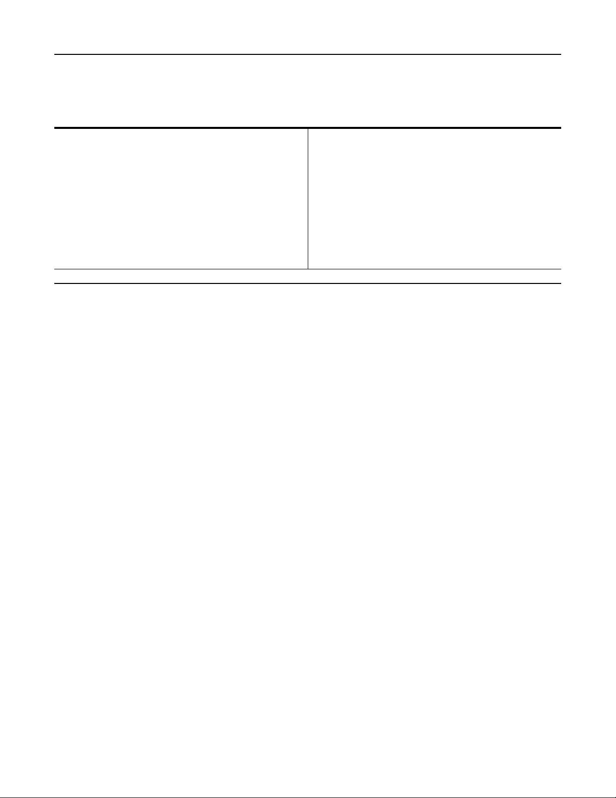
Principle of Operation
The Type 252 lter helps remove dirt, rust, chips,
scale, and moisture from the incoming high-pressure
supply before it enters the Type 1301F regulator. The
Type 1301F regulator is set to reduce this incoming
high-pressure to 100 psig / 6.9 bar. The reduced
pressure from the Type 1301F regulator is then further
reduced between 20 and 70 psig / 1.4 or 4.8 bar
to supply the pneumatic instrument. Although the
Type 67CF regulator is normally set for 20 psig /
1.4 bar outlet pressure, it can be eld-adjusted up to
35 psig / 2.4 bar outlet pressure.
The rst stage Type H120 relief valve serves to protect
the Type 67CF regulator by relieving if the reduced
pressure from the Type 1301F regulator exceeds
150 psig / 10.3 bar. The Type H800 or H120 relief
valve serves to protect downstream equipment from
overpressure by relieving if the reduced pressure
from the Type 67CF regulator exceeds the relief
setpoint. Air or gas owing from one or both of the
relief valves indicates that one or both of the regulators
are worn or damaged and must be repaired or
replaced immediately.
(1)
2
Page 3
TYPE 1301F
TYPE 252
TYPE H120 RELIEF VALVE NOT SHOWN
HIGH INLET PRESSURE
ATMOSPHERIC PRESSURE
INITIAL STEP-DOWN PRESSURE, 100 psig / 6.9 bar
FINAL OUTLET PRESSURE, 10 to 35 psig / 0.69 to 2.4 bar
RELIEF PRESSURE
Type 1367
TYPE H800
TYPE 67CF
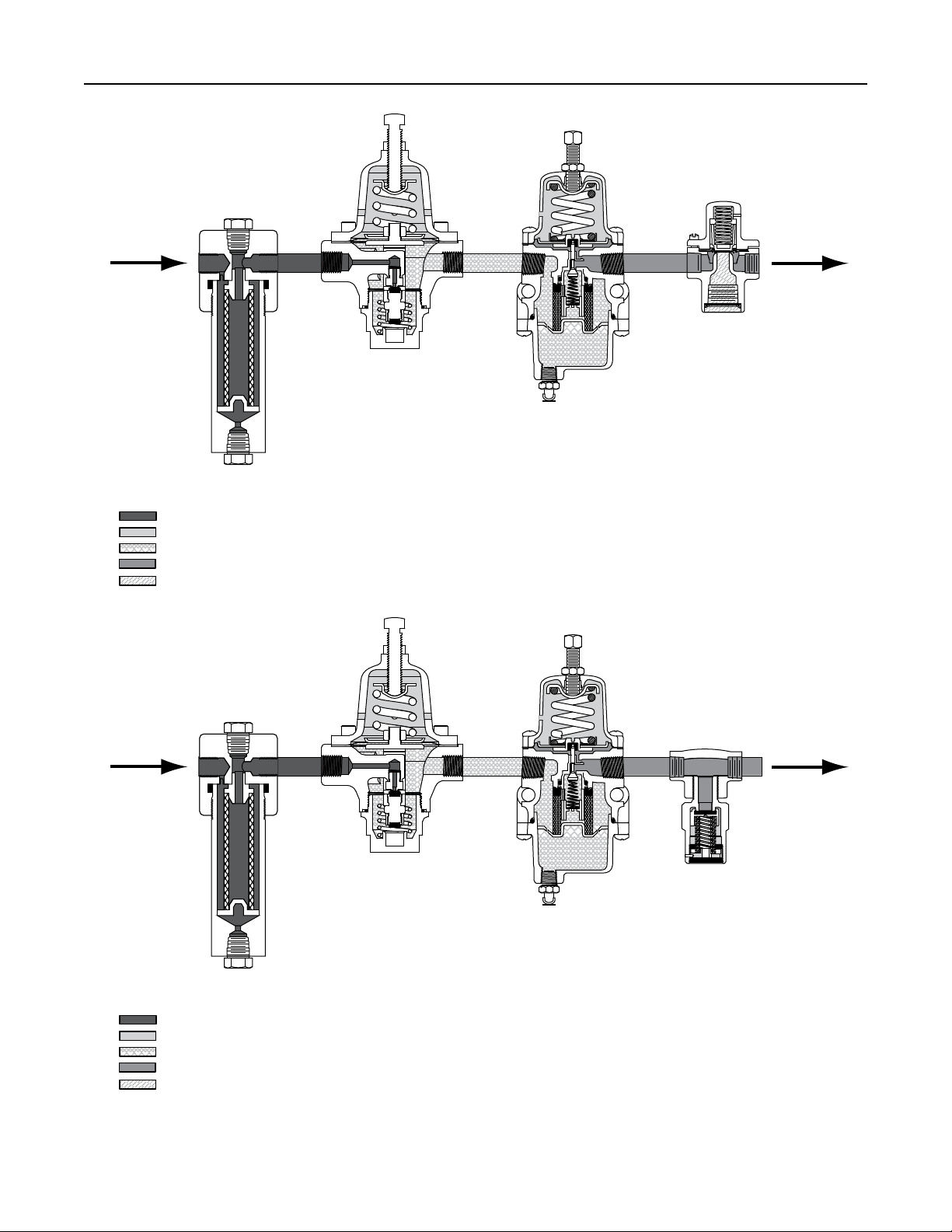
TYPE 1301F
TYPE 252
FIRST STAGE TYPE H120 RELIEF VALVE NOT SHOWN
HIGH INLET PRESSURE
ATMOSPHERIC PRESSURE
INITIAL STEP-DOWN PRESSURE, 100 psig / 6.9 bar
FINAL OUTLET PRESSURE, 10 to 35 psig / 0.69 to 2.4 bar
RELIEF PRESSURE
Figure 2. Type 1367 Operational Schematic
TYPE H120
TYPE 67CF
3
Page 4

Type 1367
Installation
All key numbers mentioned in this section appear
in Figure 2.
WARNING
!
Installing a Type 1367 instrument supply
system where its capabilities can be
exceeded or where proper operation
might be impaired may cause personal
injury, property damage, or leakage due
to bursting of pressure-containing parts
or explosion of accumulated gas. To
avoid such conditions:
• Use qualied service person to
install the Type 1367 instrument
supply system.
• Install the Type 1367 instrument
supply system where it is protected
from exposure to physical damage
and/or corrosive substances.
• Install the instrument supply system
where service conditions are within
the unit capabilities specied in
Specications. Consult your local
Sales Ofce if service conditions
exceed Specications capabilities.
Consult local Sales Ofce if
service conditions exceed
Specications capabilities.
Impairment of proper operation includes
permanently removing the Types H120
and H800 relief valves from their
respective regulators and plugging the
side outlet of the Type 1301F regulator.
Note
If the Type 1367 instrument supply
system is shipped mounted on another
unit, install that unit according to the
appropriate instruction manuals.
With an instrument supply system that is
shipped separately:
1. Make sure that there is no damage to
the components.
2. Mount the bracket of the Type 1301F regulator
(key 2) on the actuator yoke or casing.
Note
If using pipe in the following steps,
apply thread tape or pipe compound
to the pipe threads before making
the connections.
3. Install tubing or piping into the 1/4 NPT inlet
connection of the Type 252 lter (key 1) so that
ow is in the proper direction as indicated on the
lter head.
4. Install tubing or piping from the 1/4 NPT
outlet (or side) connection of the Type H800 or
tee of the Type H120 relief valve (key 5) to the
pneumatic instrument.
WARNING
!
An instrument supply system may
vent some gas to the atmosphere. In
hazardous or ammable gas service,
vented gas may accumulate, causing
personal injury, death, or property
damage due to re or explosion. Vent a
supply system in hazardous gas service
to a remote, safe location away from air
intakes or any hazardous location. The
vent lines in both of the following steps
must be protected against condensation
or clogging.
5. To remotely vent gas from the 1/2 NPT vent (or
bottom) connection of the Type H800 relief valve
(key 5), remove the screen from the Type H800
vent. Then install the appropriate size piping or
tubing into the Type H800 vent connection. The
piping or tubing should vent the gas to a safe
location, be as short and have as few bends as
possible to minimize backpressure during relief
valve operation, and have a screened vent on
its exhaust end. Install any remote vent piping
or tubing so that the vent is protected from
condensation, freezing, or any substance that
could clog it.
6. To remotely vent gas from the 1/4 NPT connection
of the street elbow (key 7) or the pipe tee (key 10),
remove the Type H120 relief valve (key 3 and/
or key 5) from the elbow or tee. Then install the
appropriate size piping or tubing into the elbow.
The piping or tubing should vent the gas to a safe
location, and be as short as possible and have as
4
Page 5

Type 1367
few bends as possible to minimize backpressure
during relief valve operation. Reinstall the
Type H120 relief on the remote end of the piping
or tubing installed in the elbow.
Startup
With installation completed and downstream
equipment adjusted, slowly open the upstream and
downstream block valves while using pressure gauges
to monitor pressure.
Adjustments
Unless specied otherwise, each instrument supply
system is factory-set for a 20 psig / 1.34 bar outlet
pressure. Consult the Types 67CF and 67CFR
regulators instruction manual for the procedure to
adjust the Type 67CF regulator (key 4, Figure 2)
anywhere within its 5 to 70 psig / 0.35 to 4.8 bar outlet
pressure range.
Shutdown
First, close the upstream shutoff valve, and then,
close the downstream shutoff valve. Next, open the
vent valve between the regulator and the downstream
shutoff valve and open the vent valve between the
regulator and the upstream shutoff valve. If vent
valves are not installed, safely bleed off both inlet and
outlet pressures and check that the regulator contains
no pressure.
WARNING
!
To avoid personal injury or equipment
damage from sudden release of
pressure or explosion of accumulated
gas, do not attempt any maintenance
or disassembly without rst isolating
the instrument supply system and
associated equipment from system
pressure and relieving all internal
pressure from the instrument supply
system and associated equipment.
To avoid personal injury or equipment
damage due to impaired operation, make
sure that the relief valves (keys 3 and 5)
are directly or remotely installed into
the appropriate outlets of the regulators
(keys 2 and 4) after maintenance
is completed.
Parts Ordering
When corresponding with your local Sales Ofce
about this unit, include the date of manufacture from
the nameplate and the type numbers and all other
pertinent information from the nameplates and other
identication appearing on each of the components.
Specify the appropriate part number when ordering
any new parts from the following list.
Parts List
Maintenance
All key numbers mentioned in this section appear
in Figure 2.
Type 1367 instrument supply systems parts are
subject to normal wear and must be inspected and
replaced as necessary. The frequency of inspection
and parts replacement depends on the severity of
service conditions and the requirements of local,
state, and federal rules and regulations. The drain
valves of both the Types 252 and 67CF regulators
(keys 1 and 4) should be opened periodically to empty
accumulated moisture.
Consult the appropriate instruction manual for
maintenance procedures on each of the components
of the Type 1367 instrument supply system.
To Provide Sour Gas Corrosion
Resistance Capability
Key Description Part Number
1 Type 252 Filter FS252-8
2 Type 1301F Regulator
For yoke mounting FS1301F-N2/M1
For casing mounting FS1301F-N2/M3
3 Type H120 Relief Valve FSH120-N150
4 Type 67CF Regulator FS67CF-N206
5 Type H800 Relief Valve FSH800-2
6 Pipe Nipple, Plated Carbon steel (3 required) - - - - - - - - - - -
7 Street Elbow, Heat-treated steel - - - - - - - - - - -
8 Nameplate, Stainless steel (not shown) - - - - - - - - - - -
9 Wire, Monel® with Lead seal (not shown) T12315T0012
1. As detailed in NACE international standard MR0175.
2. For entire assembly. See separate manual for individual part numbers.
Monel® is a trademark of Special Metals Corporation.
(1)
(2)
(2)
(2)
(2)
(2)
5
Page 6

Type 1367
A7036
8
9
1
2
7
3 6
4
5
TYPE H120 RELIEF VALVE NOT SHOWN
8
9
2
7
1
3
4
10
6
5
FIRST STAGE TYPE H120 RELIEF VALVE NOT SHOWN
Figure 3. Type 1367 Instrument Supply System Assembly
6
Page 7

For Other Than Sour Gas Corrosion
Resistance Applications
Type 1367
With Type H800
Key Description Part Number
1 Type 252 Filter FS252-8
2 Type 1301F Regulator
For yoke mounting FS1301F-2/M1
For casing mounting FS1301F-2/M3
3 Type H120 Relief Valve FSH120-150
4 Type 67CF Regulator FS67CF-206
5 Type H800 Relief Valve FSH800-2
6 Pipe Nipple, Zinc-plated
Galvanized steel (3 required) - - - - - - - - - - -
7 Street Elbow, Galvanized plated
Malleable iron - - - - - - - - - - -
8 Nameplate, Stainless steel (not shown) - - - - - - - - - - -
9 Wire, Monel® with Lead seal (not shown) T12315T0012
2. For entire assembly. See separate manual for individual part numbers.
Monel® is a trademark of Special Metals Corporation.
With Type H120
Key Description Part Number
(2)
1 Type 252 Filter FS252-4S
2 Type 1301F Regulator
(2)
For yoke mounting FS1301F-N5/M1
(2)
For casing mounting FS1301F-N5/M1
3 Type H120 Relief Valve FSH120-SS150
(2)
4 Type 67CFS Regulator FS67CFS-226
(2)
5 Type H120 Relief Valve FSH120-40
FSH120-50
FSH120-60
FSH120-70
FSH120-75
6 Pipe nipple, Stainless steel (3 required) - - - - - - - - - - -
7 Street Elbow, Stainless steel - - - - - - - - - - -
8 Nameplate, Stainless steel (not Shown) - - - - - - - - - - -
9 Wire, Monel® with lead seal (not shown) - - - - - - - - - - -
10 Pipe tee, Stainless steel - - - - - - - - - - -
(2)
(2)
7
Page 8

Type 1367
Industrial Regulators
Emerson Process Management
Regulator Technologies, Inc.
USA - Headquarters
McKinney, Texas 75069-1872, USA
Tel: +1 800 558 5853
Outside U.S. +1 972 548 3574
Asia-Pacic
Shanghai 201206, China
Tel: +86 21 2892 9000
Europe
Bologna 40013, Italy
Tel: +39 051 419 0611
Middle East and Africa
Dubai, United Arab Emirates
Tel: +971 4811 8100
For further information visit www.fisherregulators.com
The Emerson logo is a trademark and service mark of Emerson Electric Co. All other marks are the property of their prospective owners. Fisher is a mark owned by Fisher Controls International LLC,
a business of Emerson Process Management.
The contents of this publication are presented for informational purposes only, and while every effort has been made to ensure their accuracy, they are not to be construed as warranties or
guarantees, express or implied, regarding the products or services described herein or their use or applicability. We reserve the right to modify or improve the designs or specications of such
products at any time without notice.
Emerson Process Management Regulator Technologies, Inc. does not assume responsibility for the selection, use or maintenance of any product. Responsibility for proper selection, use and
maintenance of any Emerson Process Management Regulator Technologies, Inc. product remains solely with the purchaser.
Natural Gas Technologies
Emerson Process Management
Regulator Technologies, Inc.
USA - Headquarters
McKinney, Texas 75069-1872, USA
Tel: +1 800 558 5853
Outside U.S. +1 972 548 3574
Asia-Pacic
Singapore 128461, Singapore
Tel: +65 6770 8337
Europe
Bologna 40013, Italy
Tel: +39 051 419 0611
Chartres 28008, France
Tel: +33 2 37 33 47 00
TESCOM
Emerson Process Management
Tescom Corporation
USA - Headquarters
Elk River, Minnesota 55330-2445, USA
Tels: +1 763 241 3238
+1 800 447 1250
Europe
Selmsdorf 23923, Germany
Tel: +49 38823 31 287
Asia-Pacic
Shanghai 201206, China
Tel: +86 21 2892 9499
©Emerson Process Management Regulator Technologies, Inc., 1984, 2013; All Rights Reserved
 Loading...