

Page 1

Instruction Manual
Form 1095
October 2009
1305 Series
1305 Series Pressure Reducing Regulators
WARNING
!
Fisher® regulators must be installed,
operated, and maintained in accordance
with federal, state, and local codes, rules
and regulations, and Emerson Process
Management Regulator Technologies,
Inc. instructions.
If the regulator vents gas or a leak
develops in the system, service to
the unit may be required. Failure
to correct trouble could result in a
hazardous condition.
W3101
Call a gas service person to service
the unit. Only a qualied person must
install or service the regulator.
Introduction
The 1305 Series regulators are direct-operated,
pressure-reducing regulators that resist hydrate
formation and regulator freeze-up. Regulator
freeze-up resistance occurs as the pipeline gas
warms the nned inlet adaptor and the orice area.
As the gas cools within the inlet adaptor due to
pressure drop and volume expansion, the warm inlet
adaptor helps keep the gas temperature above the
freezing point of water and the hydrate formation
temperature. The regulators are suitable for service
with natural gas, air, propane, and other gases
compatible with the internal parts.
Type 1305C—1 NPT inlet and 1/4 NPT outlet
connections; 5/64-inch (2,0 mm) orice diameter.
Three springs provide 0 to 225 psig (0 to 15,5 bar)
reduced pressure ranges.
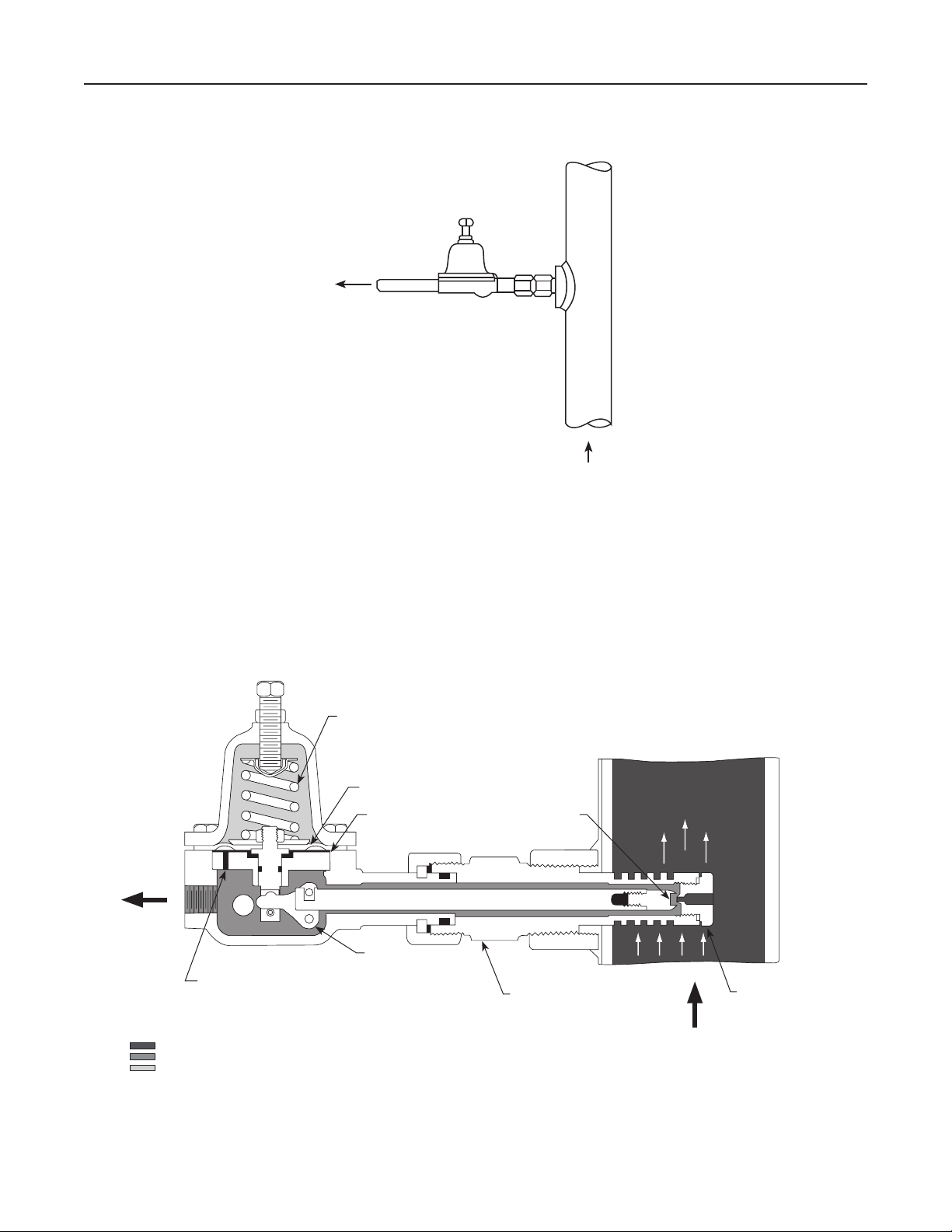
Figure 1. 1305 Series Regulator with Tapped Lower
Casing Connection
Type 1305D—same as Type 1305C except with larger
spring case and just one heavy spring for reduced
pressure range of 200 to 500 psig (13,8 to 34,5 bar).
Principle of Operation
Downstream pressure is sensed by the diaphragm
(see Figure 3) through a registration hole in the
bafe. When downstream pressure rises, pressure
under the diaphragm overcomes the spring
compression and moves the valve lever upward.
This action pushes the valve disk closer to the
orice, reducing ow through the body. Downstream
pressure returns to the setpoint value. When
downstream pressure decreases, the opposite action
takes place. The valve disk moves away from the
orice, ow through the body increases, and the
downstream pressure returns to the setpoint value.
www.emersonprocess.com/regulators
D100342X012
Page 2

1305 Series
Specications
Piping Connections
Inlet: 1 NPT
Outlet: 1/4 NPT
Operative Ambient Temperature Limits
-20° to 200°F (-29° to 93°C)
Maximum Emergency Outlet (Casing) Pressure
Type 1305C: 250 psig (17,2 bar)
Type 1305D: 550 psig (37,9 bar)
Outlet Pressure Ranges
Type 1305C
With Spring 1D387227022 (Blue):
0 to 75 psig (0 to 5,2 bar)
With Spring 1B788527022 (Unpainted):
0 to 150 psig (0 to 10,3 bar)
With Spring 1D465127142 (Red):
0 to 225 psig (0 to 15,5 bar)
Type 1305D: 200 to 500 psig (13,8 to 34,5 bar)
Maximum Allowable Inlet Pressue
4000 psig (276 bar)
(1)
(1)
Maximum Operating Outlet Pressure
Type 1305C
With Spring 1D387227022 (Blue):
75 psig (5,2 bar)
With Spring 1B788527022 (Unpainted):
150 psig (10,3 bar)
With Spring 1D465127142 (Red):
225 psig (15,5 bar)
Type 1305D: 500 psig (34,5 bar)
Orice Size
5/64-inch (2,0 mm)
Construction Materials
Lower Casing: Brass
Spring Case: Brass
Orice: 416 Stainless steel
Valve Stem: 416 Stainless steel
Valve Disk: Nylon (PA)
O-rings: Nitrile (NBR)
NACE Construction
Lower Casing: Brass
Spring Case: Brass
Orice: 316 Stainless steel
Valve Stem: 316 Stainless steel
Valve Disk: Nylon (PA)
O-rings: Nitrile (NBR)
1. The pressure/temperature limits in this Instruction Manual or any applicable code limitations should not be exceeded.
The 1305 Series regulator inlet is installed directly
in a high-pressure, warm-gas ow line. Heat from
this line is transmitted through the ns in the inlet
adaptor. The temperature of the reduced pressure
gas is raised high enough to prevent formation of
condensate and regulator freeze-up.
Installation
After the regulator has been removed from the
shipping container, inspect the regulator for shipping
damage. Be sure the body and connecting pipeline
are free of foreign material. Coat external threads
with a good grade of pipe compound. The regulator
can be installed in any position. To position the
regulator, loosen the union nut (key 8, Figure 4) and
turn the regulator to the desired position. Tighten
the union nut.
Install these regulators as shown in Figure 2. Weld
a 1-inch (25 mm) pipe coupling on the high-pressure,
warm temperature supply line. Screw the inlet adaptor
(key 3, Figure 4) into this pipe coupling so that the inlet
and orice are directly in the main ow line.
The main ow pipeline must be at least
3-inches (76 mm) in diameter.
Note
2
Page 3
REDUCED GAS
TO PILOTS
AE2715-E
A2531-1
HIGH-PRESSURE GAS
3-INCH (76 mm)
MINIMUM PIPE SIZE
1305 Series
M1038
REGISTRATION
HOLE
Figure 2. Installation of Type 1305 Regulator
SPRING
DIAPHRAGM
INLET
ADAPTOR
VALVE
DISK
BAFFLE
VALVE
LEVER
ORIFICE
INLET PRESSURE
OUTLET PRESSURE
ATMOSPHERIC PRESSURE
Figure 3. Type 1305C Operational Schematic
3
Page 4
1305 Series
Overpressure Protection
1305 Series regulators have outlet pressure ratings
that are lower than the inlet pressure ratings. Some
type of overpressure protection (such as relief valve) is
necessary if the actual inlet pressure can exceed the
outlet pressure rating.
Maximum pressure ratings are stamped on the
nameplate. Maximum emergency outlet
(casing) pressures are 250 psig (17,2 bar) for
Type 1305C regulator and 550 psig (37,9 bar) for
Type 1305D regulator.
WARNING
!
Overpressuring any portion of this
equipment may cause personal injury,
damage to regulator parts, or leaks
in the regulator due to bursting of
pressure-containing parts or explosion
of accumulated gas.
To avoid overpressure, provide an
appropriate overpressure protection
device to ensure that the pressure
limitations will not be exceeded.
The regulator should be inspected for
damage after any overpressure condition.
pressure. Cautiously release all internal
pressure from the regulator before
attempting disassembly.
Parts such as the valve disk, orice, diaphragm,
and O-rings wear out even under normal conditions.
Normal wear of the valve disk and orice is
accelerated by high-pressure drops and large amounts
of impurities in the ow stream. External sources may
also cause damage to the regulator.
Inspect the regulator periodically or after any unusual
condition. Replace parts as necessary. The frequency
of inspection and replacement depends upon the
severity of service conditions or the requirements of
state and federal laws.
Instructions are given below for disassembly and
reassembly of these regulators. Figure 4 shows key
numbers for the 1305 Series regulators.
Disassembly
1. Disconnect the outlet piping.
2. Unscrew the union nut (key 8) and slide the
regulator out of the inlet adaptor (key 3).
3. The disk holder assembly (key 5) can be
unscrewed from the stem (key 6). Replace the
disk holder assembly if the seating surface is
worn or nicked.
Adjustments
The regulator can be adjusted within the setting limits
stamped on the nameplate. Loosen the locknut
(key 20, Figure 4). To increase the outlet pressure
setting, turn the adjusting screw (key 19, Figure 4)
clockwise. Turn the adjusting screw counterclockwise
to decrease the outlet pressure setting.
If a different setting range is desired, choose an
appropriate spring from the parts list and substitute
it for the spring that is in the regulator. Be sure to
indicate the change on the nameplate.
Maintenance
WARNING
!
To avoid personal injury or equipment
damage from sudden release of pressure
or uncontrolled gas, do not attempt any
maintenance or disassembly without
rst isolating the regulator from system
4. Check, and replace if necessary, O-ring (key 7).
5. Loosen hex nut (key 20) and turn the adjusting
screw (key 19) counterclockwise to ease the
spring compression on the diaphragm.
6. Remove the machine screws (key 21). Lift off
the spring case (key 2), spring (key 17), and
upper spring seat (key 18).
7. Take hex nut (key 16) off of the pusher post
(key 11).
8. Lift off the diaphragm head (key 15) and
diaphragms (key 14).
9. An O-ring (key 13, not shown) is mounted on
the lever pin (key 12). Unscrew the lever pin
from the body and check the O-ring.
10. Take the bafe (key 28), pusher post assembly
(key 11), and lever assembly (key 10) out of
the body. Separate the lever from the pusher
post. Slip the bafe off of the pusher post to
check O-ring (key 30, if present).
4
Page 5

1305 Series
11. Inspect the orice (key 4) of the regulator by
unscrewing the inlet adaptor (key 3) and
removing it from the coupling. Unscrew the
orice. Check O-ring (key 23) also.
Reassembly
Coat external threads with a good grade of pipe
compound when reassembling the regulator.
1. Place the O-ring on the inlet adaptor and screw
in the orice.
2. Reassemble the pusher post, bafe and lever
unit. Put the unit into the body and connect the
lever to the stem. Place an O-ring on the lever
pin and screw it into the body and through
the lever.
3. Set the diaphragms on the pusher post. The
composition diaphragm goes on rst, with the
metal diaphragm placed over it. (In Type 1305D
regulators, both diaphragms are metal).
4. Set the diaphragm head over the diaphragms
and screw the hex nut onto the pusher post.
5. Put the spring and upper spring seat onto the
diaphragm head. Set the spring case on the
body. Insert the machine screws, tightening
them nger-tight only.
6. Screw the disk holder into the stem.
7. Slide the regulator into the inlet adaptor and
tighten the union nut.
8. To ensure proper slack in the diaphragm,
apply spring compression by turning the
adjusting screw clockwise. Finish tightening the
machine screws.
9. Connect the inlet and outlet piping to the
body connections.
Parts Ordering
When corresponding with your local Sales Ofce
about this equipment, be sure to include the type
number and other information stamped on
the nameplate.
When ordering replacement parts, reference the
key number of each needed part as found in the
following parts list.
Parts List
Note
In this parts list, parts marked NACE are
intended for corrosion-resistant service
as detailed in the NACE International
standard MR0175.
Key Description Part Number
1 Lower Casing, Brass (standard or NACE) 2R139212012
2 Spring Case, Brass
Type 1305C 1D383113012
Type 1305D (standard or NACE) 2P195713022
3 Inlet Adaptor
416 Stainless steel 1D900235132
316 Stainless steel (NACE) 1D9002X0012
4* Orice
416 Stainless steel 1D900335132
316 Stainless steel (NACE) 1D9003X0012
5* Valve Disk Assembly
Stainless steel/Nylon (PA) 1F1005000A2
Stainless steel/Nylon (PA) (NACE) 1F1005X0012
6 Valve Stem
416 Stainless steel 1F108835132
316 Stainless steel (NACE) 1F1088X0012
7* O-ring, Nitrile (NBR) (standard or NACE) 1D237506992
8 Union Nut, 416 Stainless steel
(standard or NACE) 1D900535132
9 Split Ring, 416 Stainless steel
(standard or NACE) 1D900635132
10 Valve Lever Assembly
Steel/303 Stainless steel 1R1394000A2
Steel (NACE) 1R1394X0012
10A Valve Lever
Steel 1R139332992
Steel, Zinc-plated steel (NACE) 1R1393X0012
10B Valve Lever Pin
303 Stainless steel 1D900835032
316 Stainless steel (NACE) 1D9008X0012
11 Pusher Post Assembly
Brass/steel 1R1397000A2
Stainless steel/Inconel® (NACE) 1R1397X0012
11A Pusher Post, Brass (standard or NACE) 1R139514012
11B Roll Pin
Carbon steel 1R139628992
Inconel® X750 (NACE) 1R1396X0012
12 Lever Support Pin
416 Stainless steel 1F100835132
316 Stainless steel (NACE) 1F1008X0012
13* O-ring, Nitrile (NBR) (not shown),
(standard or NACE) 1D687506992
14* Diaphragm (1 of each required for Type 1305C)
Type 1305C
Neoprene (CR) 1D900702112
302 Stainless steel 1D387036012
Diaphragm
Type 1305D (standard or NACE)
302 Stainless steel (2 required) 1D387036012
Neoprene (CR) (1 required) 1D900702112
15 Diaphragm Head, Steel
Type 1305C 1D387325072
Type 1305D (standard or NACE) 1K155725072
16 Hex Nut, Steel (standard or NACE) 1A309324122
*Recommended Spare Parts
Inconel® is a mark owned by Special Metals Corporation.
5
Page 6

1305 Series
4
23
5
3
7 8
9
6
12
10
11
28
1
30
14
15
2
17
20
22
19
18
16
21
C
A
N
A
D
I
A
N
P
A
T
E
N
T
S
4
8
1
,
5
4
2
1
9
5
2
P
S
I
M
A
X
O
U
T
L
E
T
F
I
S
H
E
R
G
O
V
E
R
N
O
R
,
C
O
M
A
R
S
H
A
L
L
T
O
W
N
,
I
O
W
A
P
S
I
M
A
X
I
N
L
E
T
U
.
S
.
P
A
T
E
N
T
S
2
,
5
2
0
,
3
2
0
6
,
5
7
8
,
0
0
5
TYPE
CR1399-A
Figure 4. 1305 Series Regulator
6
Page 7

1305 Series
Key Description Part Number
17 Spring, Steel, Zinc-plated steel
Type 1305C
0 to 75 psig (0 to 5,2 bar), Blue 1D387227022
0 to 150 psig (0 to 10,3 bar), Unpainted 1B788527022
0 to 225 psig (0 to 15,5 bar), Red 1D465127142
Type 1305D (standard or NACE)
200 to 500 psig (13,8 to 34,5 bar) 1K156027142
18 Upper Spring Seat, Steel
Type 1305C 1B798525062
Type 1305D (standard or NACE) 1K155828982
19 Set Screw, Steel
Type 1305C 1A368728982
Type 1305D (standard or NACE) 1K140624092
20 Hex Nut
Type 1305C, Brass 1A518014012
Type 1305D, Steel (standard or NACE) 1A354024122
*Recommended Spare Parts
Monel® is a mark owned by Special Metals Corporation.
Key Description Part Number
21 Machine Screw, Steel (6 required)
Type 1305C 1A407824052
Type 1305D (standard or NACE) 1K764524052
22 Nameplate, Brass (standard or NACE) 1P216818992
23* O-Ring, Nitrile (NBR) (standard or NACE) 1E5914X0052
24 Pipe Plug, Brass (not shown),
(standard or NACE) 1A6495X0052
27 Vent Screen, Monel
Type 1305D (standard or NACE) 0W086343062
28 Bafe, Brass (standard or NACE) 1R139814012
29 Machine Screw, not shown (2 required)
Carbon-plated steel 1E382728992
304 Stainless steel (NACE) 1E3827X0012
30* O-ring, Nitrile (NBR) (optional) 1H292306992
®
7
Page 8

1305 Series
Industrial Regulators
Emerson Process Management
Regulator Technologies, Inc.
USA - Headquarters
McKinney, Texas 75069-1872 USA
Tel: 1-800-558-5853
Outside U.S. 1-972-548-3574
Asia-Pacic
Shanghai, China 201206
Tel: +86 21 2892 9000
Europe
Bologna, Italy 40013
Tel: +39 051 4190611
Middle East and Africa
Dubai, United Arab Emirates
Tel: +971 4811 8100
For further information visit www.emersonprocess.com/regulators
The Emerson logo is a trademark and service mark of Emerson Electric Co. All other marks are the property of their prospective owners. Fisher is a mark owned by Fisher Controls, Inc., a
business of Emerson Process Management.
The contents of this publication are presented for informational purposes only, and while every effort has been made to ensure their accuracy, they are not to be construed as warranties or
guarantees, express or implied, regarding the products or services described herein or their use or applicability. We reserve the right to modify or improve the designs or specications of such
products at any time without notice.
Emerson Process Management does not assume responsibility for the selection, use or maintenance of any product. Responsibility for proper selection, use and maintenance of any Emerson
Process Management product remains solely with the purchaser.
Natural Gas Technologies
Emerson Process Management
Regulator Technologies, Inc.
USA - Headquarters
McKinney, Texas 75069-1872 USA
Tel: 1-800-558-5853
Outside U.S. 1-972-548-3574
Asia-Pacic
Singapore, Singapore 128461
Tel: +65 6777 8211
Europe
Bologna, Italy 40013
Tel: +39 051 4190611
Gallardon, France 28320
Tel: +33 (0)2 37 33 47 00
TESCOM
Emerson Process Management
Tescom Corporation
USA - Headquarters
Elk River, Minnesota 55330-2445 USA
Tel: 1-763-241-3238
Europe
Selmsdorf, Germany 23923
Tel: +49 (0) 38823 31 0
©Emerson Process Management Regulator Technologies, Inc., 1953, 2009; All Rights Reserved
 Loading...