

Page 1
Monitoring
For Business-Critical Continuity™
Liebert ®SiteLink-E
Installation Manual - Liebert SiteLink-2E, Liebert SiteLink-4E and Liebert SiteLink-12E
™
Page 2

Page 3

TABLE OF CONTENTS
1.0 PRODUCT OVERVIEW . . . . . . . . . . . . . . . . . . . . . . . . . . . . . . . . . . . . . . . . . . . . . . . . . . . . . 1
2.0 INSTALLING THE LIEBERT SITELINK-E MODULE . . . . . . . . . . . . . . . . . . . . . . . . . . . . . . . . . .2
2.1 Preparations for Mounting the Module. . . . . . . . . . . . . . . . . . . . . . . . . . . . . . . . . . . . . . . . . . . 2
2.1.1 Choose a Location to Install the Liebert SiteLink-E . . . . . . . . . . . . . . . . . . . . . . . . . . . . . . . . . 2
2.2 Enclosure Diagrams . . . . . . . . . . . . . . . . . . . . . . . . . . . . . . . . . . . . . . . . . . . . . . . . . . . . . . . . . . 2
3.0 CONNECT INPUT POWER WIRING . . . . . . . . . . . . . . . . . . . . . . . . . . . . . . . . . . . . . . . . . . . .5
3.1 Power Wiring . . . . . . . . . . . . . . . . . . . . . . . . . . . . . . . . . . . . . . . . . . . . . . . . . . . . . . . . . . . . . . . 5
3.1.1 Input Power Requirements . . . . . . . . . . . . . . . . . . . . . . . . . . . . . . . . . . . . . . . . . . . . . . . . . . . . . 5
3.2 Connect Input Power—AC or DC . . . . . . . . . . . . . . . . . . . . . . . . . . . . . . . . . . . . . . . . . . . . . . . 6
4.0 COMMUNICATION AND CONTROL WIRING. . . . . . . . . . . . . . . . . . . . . . . . . . . . . . . . . . . . . . .7
4.1 IGM Communication . . . . . . . . . . . . . . . . . . . . . . . . . . . . . . . . . . . . . . . . . . . . . . . . . . . . . . . . . 7
4.1.1 Wiring IGM Ports . . . . . . . . . . . . . . . . . . . . . . . . . . . . . . . . . . . . . . . . . . . . . . . . . . . . . . . . . . . . . 8
4.2 RS-485 and ARC156 Wiring Considerations . . . . . . . . . . . . . . . . . . . . . . . . . . . . . . . . . . . . . . 9
4.3 Wiring for BACnet/ARC156 Network . . . . . . . . . . . . . . . . . . . . . . . . . . . . . . . . . . . . . . . . . . . . 9
4.4 Wiring Port S1 . . . . . . . . . . . . . . . . . . . . . . . . . . . . . . . . . . . . . . . . . . . . . . . . . . . . . . . . . . . . . 10
4.4.1 Wiring Port S1 for RS-485 Network—Four-Wire . . . . . . . . . . . . . . . . . . . . . . . . . . . . . . . . . . . 10
4.4.2 Wiring Port S1 for RS-485—Two-Wire . . . . . . . . . . . . . . . . . . . . . . . . . . . . . . . . . . . . . . . . . . . 11
4.4.3 Wiring Port S1 for RS-232 . . . . . . . . . . . . . . . . . . . . . . . . . . . . . . . . . . . . . . . . . . . . . . . . . . . . . 12
4.5 Wiring a Modem for Half-Router Communication—Port S1 . . . . . . . . . . . . . . . . . . . . . . . . . 12
5.0 SPECIFICATIONS. . . . . . . . . . . . . . . . . . . . . . . . . . . . . . . . . . . . . . . . . . . . . . . . . . . . . . . .13
APPENDIX A-COMMUNICATION PROTOCOL AND WIRING CONSIDERATIONS . . . . . . . . . . . . . . . . .15
A.1 Differences Between RS-485 and RS-422 . . . . . . . . . . . . . . . . . . . . . . . . . . . . . . . . . . . . . . . . 15
A.2 Termination . . . . . . . . . . . . . . . . . . . . . . . . . . . . . . . . . . . . . . . . . . . . . . . . . . . . . . . . . . . . . . . 15
A.3 Bias . . . . . . . . . . . . . . . . . . . . . . . . . . . . . . . . . . . . . . . . . . . . . . . . . . . . . . . . . . . . . . . . . . . . . . 16
i
Page 4

FIGURES
Figure 1 Liebert SiteLink-E layout—power and communication connections, ports and switches . . . . . . . 1
Figure 2 Module dimensions, without enclosure . . . . . . . . . . . . . . . . . . . . . . . . . . . . . . . . . . . . . . . . . . . . . . . 2
Figure 3 Enclosure dimensions—overall . . . . . . . . . . . . . . . . . . . . . . . . . . . . . . . . . . . . . . . . . . . . . . . . . . . . . 3
Figure 4 Enclosure dimensions—Wall mount . . . . . . . . . . . . . . . . . . . . . . . . . . . . . . . . . . . . . . . . . . . . . . . . . 3
Figure 5 Enclosure dimensions—Floor mount . . . . . . . . . . . . . . . . . . . . . . . . . . . . . . . . . . . . . . . . . . . . . . . . . 4
Figure 6 Power connections . . . . . . . . . . . . . . . . . . . . . . . . . . . . . . . . . . . . . . . . . . . . . . . . . . . . . . . . . . . . . . . . 6
Figure 7 IGM connections . . . . . . . . . . . . . . . . . . . . . . . . . . . . . . . . . . . . . . . . . . . . . . . . . . . . . . . . . . . . . . . . . 8
Figure 8 Liebert precision cooling units networked with Liebert SiteLink-E modules. . . . . . . . . . . . . . . . . 8
Figure 9 BACnet/ARC156 Network port . . . . . . . . . . . . . . . . . . . . . . . . . . . . . . . . . . . . . . . . . . . . . . . . . . . . . 9
Figure 10 Liebert SiteLink-E modules in ARCnet network . . . . . . . . . . . . . . . . . . . . . . . . . . . . . . . . . . . . . . 10
Figure 11 Port S1 jumpers and DIP switches . . . . . . . . . . . . . . . . . . . . . . . . . . . . . . . . . . . . . . . . . . . . . . . . . 11
Figure 12 RS-232 connection to Port S1 . . . . . . . . . . . . . . . . . . . . . . . . . . . . . . . . . . . . . . . . . . . . . . . . . . . . . . 12
Figure 13 Fabricated cable for modem in half-router communication . . . . . . . . . . . . . . . . . . . . . . . . . . . . . . 12
TABLES
Table 1 Specifications. . . . . . . . . . . . . . . . . . . . . . . . . . . . . . . . . . . . . . . . . . . . . . . . . . . . . . . . . . . . . . . . . . . 13
Table 2 Communication ports, protocols and settings . . . . . . . . . . . . . . . . . . . . . . . . . . . . . . . . . . . . . . . . . 14
ii
Page 5
Product Overview
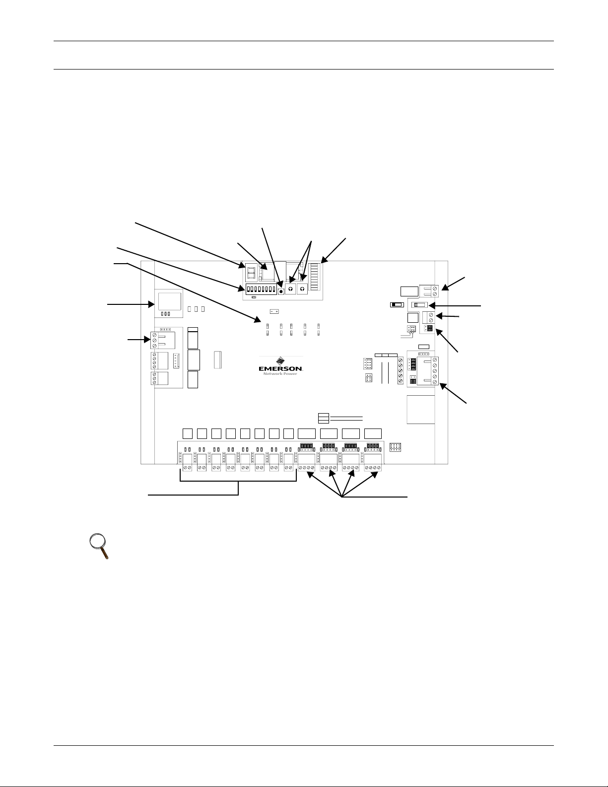
1.0 PRODUCT OVERVIEW
The Liebert SiteLink-E® interface module is a BACnet router that provides the communications link
between Liebert units and other protocols and modules. The Liebert SiteLink-E module communicates with Liebert equipment such as environmental units, UPSs, frequency converters and power
distribution units.
See Figure 1 for port locations.
Figure 1 Liebert SiteLink-E layout—power and communication connections, ports and switches
All features, including ports
available in same configuration
on all models, except where noted
Module Status
Indicator
DIP Switches
DIP
Switch
Key
Ethernet
Port
ARCnet 156 Port
IGM Ports
(RS-422) not present on
SSW-2E or SSW-4E)
SL-12E
10/100 B aseT
Et hernet Por t
100 LAN LIN K
BACnet
Over ARCNET156 KBaud
BT485
Net +
Net -
Shiel d
Gnd
Rnet +
Rnet -
+12V
Xnet +
Xnet -
Gnd
Port 1
Net-
Net+
Format Button
Battery
Module
Status
Err or C od e s:
Chase = OK
0 = Download required
1 = Control P rogram Error
2 = RAM ful l
3 = Comm setup error
4 = Syst em error
8 = Formatting
Blinki ng Dot = “Run”
®
ARC net
Port
Local
Rnet
Access
Xnet
Remote
Expansion
Port 2
Port 3
Port 4
Net-
Net-
Net+
Net+
Net+
O
N
Port 5
Net-
Net+
18234567
3V Lithium Battery
Pow er
CR-123A
LED
12345Sw
On
Assi gned0+100
Off
Default
Enhanced A cces s
on Rnet
SiteLi nk-E
SSW-12E
Port 6
Port 7
Net-
Net-
Net+
Net+
Address
Switches
0
1
0
1
9
9
2
2
8
8
3
3
7
7
4
4
6
6
5
5
10 's 1' s
Module
Address
Enable
Enable
Disabl e
IP A ddr
Net-
Disabl e
Address MSTP
PTP
on S1
on S1
Port 8
Port 9 Po rt 1 0 Port 1 1 Po rt 12
Net-
Net+
Communication
Status LEDs
ARCnet transmit
ARCnet receive
Archive Valid
Port S1 transmit
Port S1 rec eiv e
Battery low
Ports 9-12
4 wire
2 wire
EIA-232
24Vac, 24V A, 1A, 50-60 Hz
26Vdc, 10W , 0.4A
Use Copper C onductors O nly
485-4w
485-2w
Class 2
Ground
24ac/26dc
Power
On Off
Exte r na l
Gnd
Batte ry
+3V
Ext. B att.
Int . Batt .
Port S1
EIA-2324 wire2 wire
EIA- 2 32
EIA- 4 85
Signal Ground
DCD
n/c
Rx-
DTR
n/c
Rx+
Net-
Tx-
Net+
Tx+
Rx-Rx+Tx-Tx +
n/cn/cNet-Net+
n/cGndRxTx
Ports 9-12
BT485
Rx
Tx
EIA- 48 5
EIA- 23 2
Ground and
24VAC Terminals
External Battery
Connection
Battery
Jumper
S1 Port
(RS-232 or RS-485)
Ports for Other Emerson
Communication Protocols
(RS-422, RS-232 and RS-485
(2 ports on SSW-2E, 4 on other models)
Power Switch
NOTE
This equipment has been tested and found to comply with the limits for a Class A digital
device, pursuant to Part 15 of the FCC Rules. These limits are designed to provide reasonable
protection against harmful interference when the equipment is operated in a commercial
environment. This equipment generates, uses and can radiate radio frequency energy and, if
not installed and used in accordance with the instruction manual, may cause harmful
interference to radio communications. Operation of this equipment in a residential area is
likely to cause harmful interference that the user alone must correct.
1
Page 6
2.0 INSTALLING THE LIEBERT SITELINK-E MODULE
The Liebert SiteLink-E module comes in an enclosure for mounting on the wall or floor.
2.1 Preparations for Mounting the Module
2.1.1 Choose a Location to Install the Liebert SiteLink-E
The Liebert SiteLink-E module’s installation location must be easily accessible, within the allowable
cable-run distances for communication wiring and have about 2 in. (51mm) on all sides for wiring and
service.
• Refer to the following drawings in 2.2 - Enclosure Diagrams:
Figure 3 - Enclosure dimensions—overall
Figure 4 - Enclosure dimensions—Wall mount
Figure 5 - Enclosure dimensions—Floor mount
2.2 Enclosure Diagrams
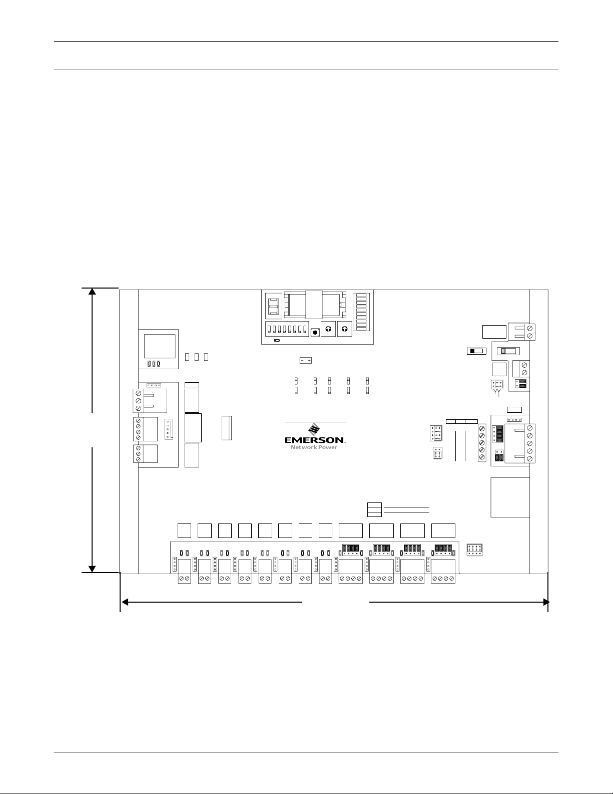
Figure 2 Module dimensions, without enclosure
Xnet
Module
St atus
Error Codes:
Chase = OK
0 = Downl oad required
1 = Control P rogram Error
2 = RAM ful l
3 = Comm setup error
4 = Sys tem error
8 = Formatting
Blinking Dot = “Run”
Local
Access
18234567
O
N
3V L ith iu m Ba tter y
Pow er
CR-123A
LED
12345Sw
On
Ass igned0+100
Off
Default
Enhanc ed Acc ess
on Rnet
SiteLink-E
SSW-12E
IP A ddr
0
1
0
9
9
2
8
8
3
7
7
4
6
6
5
10 's 1' s
Module
Addres s
Enabl e
Dis able
Address MSTP
on S1
1
2
3
4
5
Enabl e
Dis able
7-7/8"
200mm
SL- 12E
10 /100 BaseT
Et hernet Por t
100 LAN LIN K
®
BACnet
Over ARCNET156 KB aud
BT485
Net +
AR C net
Net -
Port
Shield
Gnd
Rnet +
Rnet
Rnet -
+12V
Xnet +
Remote
Xnet -
Expans ion
Gnd
Installing the Liebert SiteLink-E Module
EI A-2 32
EI A-4 85
n/c
n/c
Net-
Net+
24Vac, 24VA, 1A, 50-60 H z
26Vdc, 10W, 0.4A
Use C opper Conductors Onl y
Class 2
Power
On Off
External
Batte ry
Ex t. Batt .
Int . Batt .
Port S1
EIA-2324 wire2 wire
Si gnal Ground
DCD
Rx-
DTR
Rx+
Rx
Tx-
Tx
Tx+
Ground
24ac/26dc
Gnd
+3V
on S1
PTP
AR Cnet transmi t
AR Cnet receiv e
Archive Valid
Port S1 transmit
Port S1 receiv e
Battery low
485-4w
485-2w
BT485
Por t 1
Port s 9- 12
4 wire
2 wire
Por t 2
Por t 3
Por t 4
Por t 5
Por t 6
Por t 7
Por t 8
Ne t-
Ne t-
Ne t-
Ne t-
Ne t-
Ne t-
Ne t-
Net+
Net+
Net+
Net+
Net+
Net+
Ne t-
Net+
Net+
EIA-232
Por t 9 Por t 10 Por t 11 Por t 12
Rx-Rx+Tx-Tx +
n/cn/cNet-Net+
n/cGndRxTx
Port s 9-12
EIA-485
EIA-232
11-5/1 6"
287mm
Dimensions are identical for
Liebert Sitelink-2E
Liebert Sitelink-4E
Liebert Sitelink-12E
2
Page 7
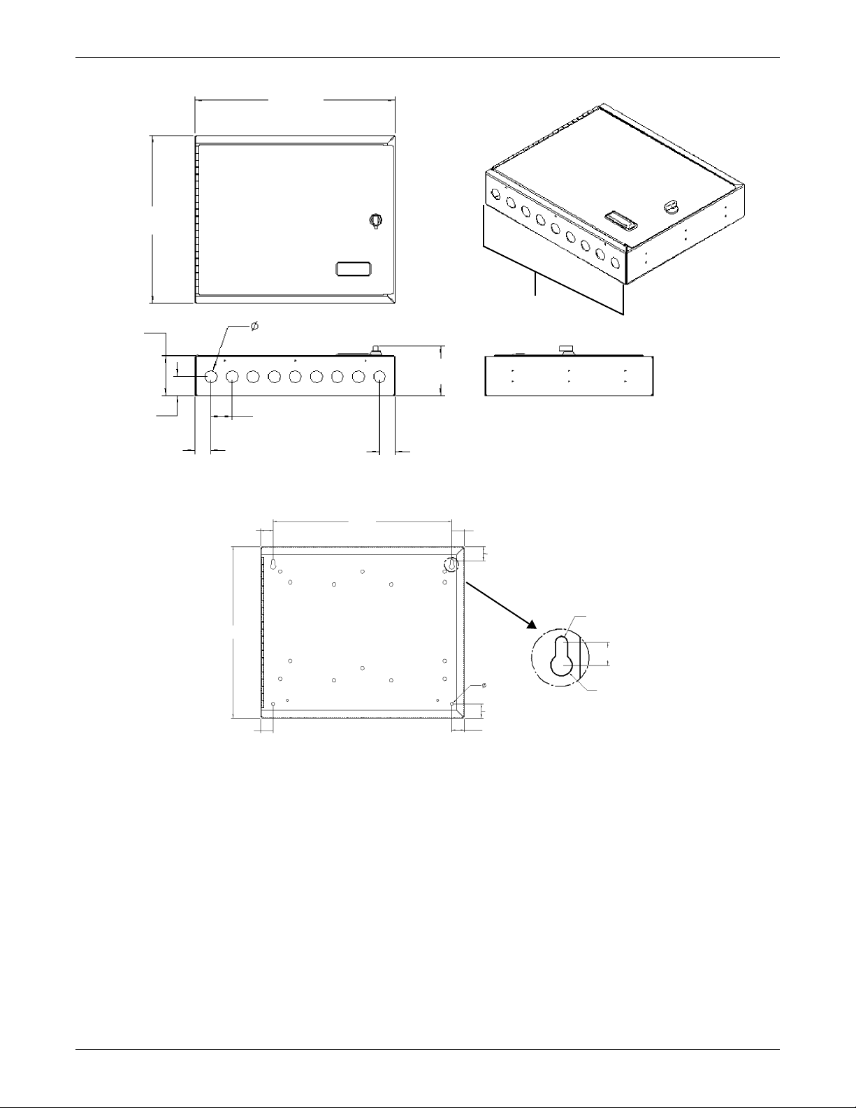
Figure 3 Enclosure dimensions—overall
14.25"
(362mm)
12"
(304.8mm)
2.85"
(72.3mm)
0.88"
(22.2mm)
9 places each end
Installing the Liebert SiteLink-E Module
Wiring knockouts
(Top and Bottom)
3.55"
(90.1mm)
1.38"
(34.9mm)
1.12"
(28.6mm)
1.5"
(38.1mm)
1.12"
(28.6mm)
Figure 4 Enclosure dimensions—Wall mount
0.88"
(22.2mm)
12"
(304.8mm)
0.88"
(22.2mm)
Back of Liebert
SiteLink-E Enclosure
12.5"
(317.5mm)
A
0.88"
(22.2mm)
1"
(25.4mm)
12
places
0.2"
(5.4mm)
1"
(25.4mm)
0.88"
(22.2mm)
DETAIL A
2 places
Dimensions are identical for
Liebert Sitelink-2E
Liebert Sitelink-4E
Liebert Sitelink-12E
0.11"
R
(2.7mm)
0.4"
(10.2mm)
0.19"
R
(4.7mm)
Dimensions are identical for
Liebert Sitelink-2E
Liebert Sitelink-4E
Liebert Sitelink-12E
3
Page 8
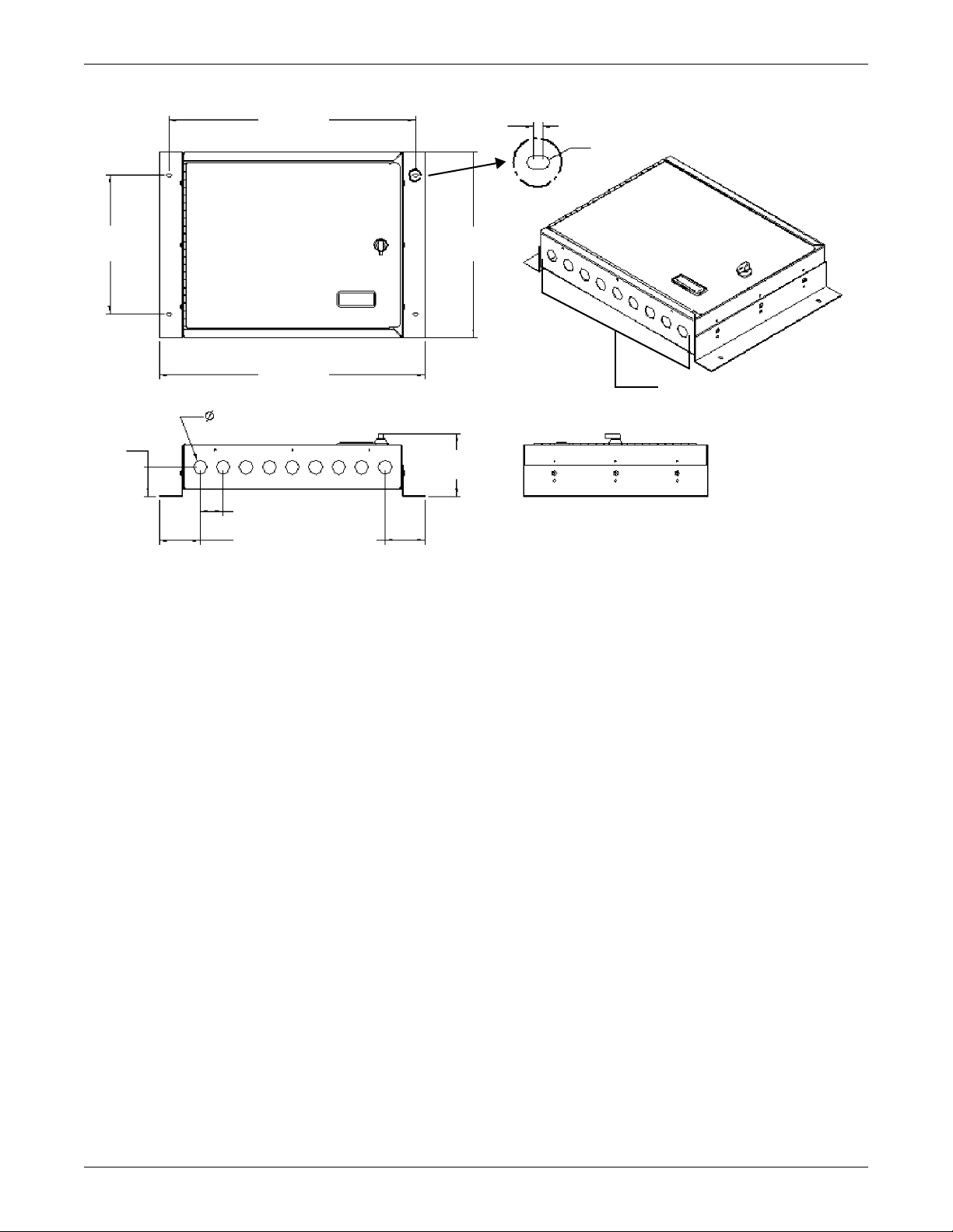
Figure 5 Enclosure dimensions—Floor mount
16"
(406.4mm)
0.16"
(4mm)
Installing the Liebert SiteLink-E Module
0.11"
R
(2.8mm)
9"
(228.6mm)
1.88"
47.6mm)
(438.2mm)
0.88"
(22.2mm)
1.5"
(38.1mm)
2.62"
(66.7mm)
17.25"
9 places each end
2.62"
(66.7mm)
B
4.05"
(102.8mm)
DETAIL B
14 places
Wiring knockouts
(Top and Bottom)
Dimensions are identical for
Liebert Sitelink-2E
Liebert Sitelink-4E
Liebert Sitelink-12E
4
Page 9

3.0 CONNECT INPUT POWER WIRING
3.1 Power Wiring
WARNING
Risk of electric shock. Can cause injury or death.
Disconnect all local and remote electric power supplies before working within.
The Liebert SiteLink-E unit must be connected by a licensed and qualified electrician only.
Ensure that the unit is electrically isolated for the duration of the connection operation and is
secured against unauthorized startup.
CAUTION
!
Do NOT turn the module On. Turning the module On before it is checked and approved by a
properly trained and qualified specialist may void the warranty.
The module should be turned on by a factory-trained specialist only.
The Liebert SiteLink-E module is a Class 2 device (less than 30VAC, 0.4A). Take appropriate isolation measures when mounting the Liebert SiteLink-E module in a control panel where non-Class 2
devices (120VAC or greater) or wiring are present.
Several modules may be powered from the same transformer if:
•the modules have the same polarity
• the transformer’s power rating is at least 20% greater than needed for the modules
For example, if the transformer is rated for 50VA and two modules, each rated at 20VA, are con-
nected, the power trunk uses a recommended 80% of the transformer’s power (20+20=40).
Connect Input Power Wiring
3.1.1 Input Power Requirements
The Liebert SiteLink-E is available in 50Hz and 60Hz models. The unit has an operating range of
21.6VAC to 26AVAC. If voltage measured at the module’s power input terminals is outside this range,
the module may not work properly.
5
Page 10

3.2 Connect Input Power—AC or DC
Liebert SiteLink-E modules may be powered with either alternating current or direct current within
the operating range of 21.6-26.4 volts. The input power terminals are in the upper right corner of the
module (see Figure 1 for location).
1. Turn the Liebert SiteLink-E module’s power switch Off.
This prevents the module from being powered up before the wiring is completed and the proper
voltage is verified.
2. Make sure the 24VAC power source is Off.
3. Pull the screw terminal connector from the control module’s power terminals labeled 24VAC/DC
and Gnd.
4. Connect the transformer wires to the screw terminal connector (see Figure 6).
5. Apply power to the power supply.
6. Measure the voltage at the Liebert SiteLink-E’s power input terminals to verify that the voltage
is within the operating range of 21.6-26.4 VAC.
7. Insert the screw terminal connector into the Liebert SiteLink-E’s power terminals.
Figure 6 Power connections
Connect Input Power Wiring
Input Power
Terminal Label
(use as connection guide
AC Power
Ground
24ac/26dc
AC/DC Power Input
Terminals (upper right corner
of Liebert SiteLink-E module)
DC Power
GND
+VIN 12V
Input
-VIN
VDD
VSS
Output
6
Page 11

4.0 COMMUNICATION AND CONTROL WIRING
NOTICE
Communication wiring must be performed in accordance with industry standards. All
methods, wiring and connections must comply with local and national codes.
Communication cables must not be kinked or otherwise damaged during installation. Kinked
cables must be replaced.
Communication cables must be properly supported every four feet (1.2m) or less.
4.1 IGM Communication
Liebert SiteLink-E uses the Information Gathering Module Network protocol to communicate to other
Liebert units over the RS-422 protocol. IGM is a point-to-point protocol, where one device connects
directly to another and only those two devices communicate with each other.
NOTE
If shielded cable is used, connect the shield wire to earth (ground) at the Liebert equipment.
Do not ground the shield at the Liebert SiteLink-E.
Liebert SiteLink-E modules have up to 12 IGM ports, depending on the model. The ports are along
the bottom of the module (see Figure 1).
Communication and Control Wiring
7
Page 12

4.1.1 Wiring IGM Ports
1. Connect the IGM wiring to the SiteLink-E IGM ports, using the labels above the ports as a guide
(see Figure 7).
2. If using a four-wire connection, set the jumpers, located behind the terminals, as required for the
protocol to be implemented. A guide is at the lower right corner of the module’s housing.
Figure 7 IGM connections
Net+
Net-
Ports 1 -8 on
Liebert SiteLink-E
SSW-12E
Connect
Communication Wiring
to Terminals
According to Labels
Above Ports
Jumpers
(on 4-Wire
Terminals
only)
Communication and Control Wiring
Ports 1-2 on Liebert SiteLink-E SSW-2E
Ports 1-4 on Liebert SiteLink-E SSW-4E
Ports 9-12 on Liebert SiteLink-E SSW-12E
4 wire
2 wire
EIA-232
Tx + Tx - Rx + Rx -
Net + Net - n/c n/c
Tx Rx Gnd n/c
Ports 9-12
EIA-485
EIA-232
Two-Wire IGM Port
Terminals
on Liebert SiteLink-E
Four-Wire IGM Port
on Liebert SiteLink-E
Figure 8 Liebert precision cooling units networked with Liebert SiteLink-E modules
Jumper
Setting
Guide
8
Page 13

4.2 RS-485 and ARC156 Wiring Considerations
An RS-485 network is intended to be configured as a linear bus with daisy-chained connections (star
topologies are not recommended). Termination in RS-485 and ARC156 setups is usually applied to
both ends of the network (see 4.4.1 - Wiring Port S1 for RS-485 Network—Four-Wire).
Repeaters often are required when connecting 32 or more RS-485 or ARC156 devices or when using
ARC156 cable segments longer than 2000 feet. Refer to the BMS documentation for information on
when to use repeaters.
To reduce communication and data errors, terminate each end of the network with a resistor whose
value equals the network's characteristic impedance. Some third-party manufacturers provide a
built-in resistor that you enable or disable with a jumper. Make sure that only devices at the end of a
network have termination enabled.
EXAMPLE: If the network’s characteristic impedance is 120 Ohms, terminate the network by
placing a 120 Ohm resistor across the Net+ and Net- connectors of the Liebert SiteLink-E and a
120 Ohm resistor across the + and - connectors of the furthest third-party device.
Bias must be applied to each RS-485 network segment. To add bias to a network segment, put the
bias jumper in place on the DIAG485 that is in the middle of the segment. You can use additional
DIAG485s with the bias jumper removed to monitor network communication, but only one
DIAG485 may have the bias jumper in place.
4.3 Wiring for BACnet/ARC156 Network
Communication and Control Wiring
Network Liebert SiteLink-E modules to other Liebert Site Scan modules using the ARCnet port. Set
the baud rate to 156 Kbps for all modules connected to the ARCnet156 network.
NOTE
Use the same polarity throughout the network segment.
1. Be sure the module’s power is Off before beginning to connect wiring for the ARCnet port.
2. Check the network communication wiring for shorts and grounds.
3. Locate the BACnet terminal location in the upper left corner of the Liebert SiteLink-E module
(see Figure 1).
4. Connect the communication wiring to the control module’s screw terminals labeled Net +, Net and Shield using the labels near the ARCnet port as a guide. For details, see Figure 9..
Figure 9 BACnet/ARC156 Network port
Wiring
Termi nals
BACnet
Over ARCNET156 KBaud
BT485
Net +
Net -
®
Connect Communication
Wiring to Terminals Using
Label Behind Port as
Guide
ARCnet
Port
Shield
9
Page 14

Figure 10 Liebert SiteLink-E modules in ARCnet network
Communication and Control Wiring
Term
Term
Term
4.4 Wiring Port S1
Port S1 on the Liebert SiteLink-E accommodates these connection types:
• RS-485 four-wire
• RS-485 two-wire
•RS-232
These ports and protocols enable connection to Liebert equipment or to third-party devices, such as a
Building Management System.
4.4.1 Wiring Port S1 for RS-485 Network—Four-Wire
NOTE
Use the same polarity throughout the network segment.
The baud rate of the control module's port must match the baud rate of the third party device.
The baud rate may be set in the module driver properties in Liebert SiteScan
Integration Guide for the third-party protocol.
1. Be sure that power to the Liebert SiteLink-E is Off before beginning to connect wiring.
2. Check the communication wiring for shorts and grounds.
3. Wire the Liebert SiteLink-E to the third-party device, using the labels near the Port S1 as a guide
(see Figure 11 for details).
4. Set the RS-232 or RS-485 jumper to RS-485.
5. Set the MS/TP on S1 DIP switch to Enable (On).
6. Set the PTP on S1 DIP switch to Disable (Off).
Term
™
Web. See the
10
Page 15

4.4.2 Wiring Port S1 for RS-485—Two-Wire
For connecting the Liebert SiteLink-E Port S1 to a BMS that uses two-wire RS-485:
• Liebert recommends using shielded, 18-24AWG twisted pair wiring.
• The distance from the Liebert SiteLink-E module to the first RS-485 device depends on the communications baud rate. This distance seldom should exceed 3,000 ft. (914.4m) at 9600 baud.
1. Be sure that power to the Liebert SiteLink-E is Off before beginning to connect wiring.
2. Check the communication wiring for shorts and grounds.
3. Wire the Liebert SiteLink-E to the third-party device, using the labels near Port S1 as a guide
(see Figure 11 for details).
4. Set the RS-232 or RS-485 jumper to RS-485.
5. Set the MS/TP on S1 DIP switch to Enable (On).
6. Set the PTP on S1 DIP switch to Disable (Off).
Figure 11 Port S1 jumpers and DIP switches
Connect Communication Wiring
to Terminals According to Labels
Behind Ports
Set Jumpers for RS-232
and RS-485 According
to Labels
Communication and Control Wiring
Jumpers for
RS-232 and
RS-485
Set Jumpers for Using
2-Wire or 4-Wire 485
Cables According
to Labels
12345678
O
N
Port S1
2 wire 4 wi re EIA-232
EIA-485
EIA-232
Signal Ground
DCD
Rx -
n/c
DTR
Rx +
n/c
485-4w
485-2w
Net-
Net+
Set DIP switch 5 to Disable for MS/TP
Set DIP switch 4 to Enable for MS/TP
Set DIP switch 4 to Disable for PTP
Sw
12345
Rx
Tx -
Tx
Tx +
Set DIP switch 5 to Enable for PTP
BT485
Port S1
(at bottom right corner
of module
Terminals
EnableAssigned Enable+100On
DIP switches
(at top of module, near battery
Enhanced Access
On Rn et
11
IP Addr Address
DIP switch Labels
(in upper middle of module)
MSTP
On S 1
DisableDisable+0DefaultOff
PTP
On S1
Page 16

4.4.3 Wiring Port S1 for RS-232
NOTE
Use the same polarity throughout the network segment.
Use the same baud rate for all control modules on the network segment.
When connecting the Liebert SiteLink-E Port S1 to a third-party device that uses RS-232:
• Liebert recommends using 18-28AWG wiring.
• Most RS-232 cables are not twisted pair, but twisted-pair wiring is acceptable.
• The distance from the Liebert SiteLink-E to the RS-232 BMS interface should not exceed 50 ft.
(15.2m).
To connect a third-party, RS-232 device to Port S1:
1. Be sure that power to the Liebert SiteLink-E module is Off before beginning to connect wiring.
2. Check the communication wiring for shorts and grounds.
3. Set the RS-232 or RS-485 jumper to RS-232.
Refer to Figure 11 and to the labels on the Liebert SiteLink-E housing.
4. Connect the communication wiring to the control module’s screw terminals labeled Tx, Rx, and
Signal Ground on Port S1, and jumper the DTR and DCD terminals.
Refer to Figure 11 and to the labels on the Liebert SiteLink-E housing.
5. Set the MS/TP on S1 DIP switch 4 to Disable (Off).
The DIP switches are at the top of the Liebert SiteLink-E module, near the battery; see Figure 1
for the DIP switch location and Figure 11 for setting positions.
6. Set the PTP on S1 DIP switch 5 to Enable (On).
Figure 12 RS-232 connection to Port S1
Communication and Control Wiring
Third-Party
Network
4.5 Wiring a Modem for Half-Router Communication—Port S1
1. Turn Off power to the Liebert SiteLink-E.
2. Connect the modem to Port S1 using a standard modem cable connected to an S2-DB9 adapter,
available from Liebert, or a cable made using the wiring diagram in Figure 13.
3. Set the PTP on S1 DIP switch to Enable (ON).
Refer to Figure 11 for determining the wiring connections.
Figure 13 Fabricated cable for modem in half-router communication
Port S1 (5-Pin) Modem (25-Pin)
TX 1
RX 2
* DTR 3
* DCD 4
GND 5
T2 X
3 RX
20 DTR * †
8 DCD * †
7 GND
* Wire connection usually not needed
** Needed only if hardware handshaking is used
† DCD can be hooked up to the DTR signal for
self-handshaking
RS-232
Point-to-Point
12
Page 17

5.0 SPECIFICATIONS
Table 1 Specifications
PHYSICAL
Module Dimensions, W x H x D, in. (mm) 11-1/4 x 7-1/2 x 1-1/4 (286 x 191 x 32)
Enclosure Dimensions, W x H x D, in. (mm) 14-1/4 x 12 x 3-9/16 (362 x 305 x 90)
Recommended Panel Depth, in. (mm) 2-3/4 (70)
Weight, Module Only, lb. (kg) 1.4 (0.64 kg)
Input Power
Environmental Operating Range -20 to 140°F (-29 to 60°C), 10–90% RH non-condensing
BATTERY
SYSTEM FEATURES
Microprocessor
Memory
AGENCY
BACnet Support
Listings UL-916 (PAZX); cUL-916 (PAZX7); FCC Part 15-Subpart B-Class A
24 VAC ±10%, 50–60 Hz, 24 VA
26 VDC ±10%, 10W
Type 10-year Lithium CR123A
Life 720 hours data retention maximum
32-bit Motorola Power PC microprocessor with cache memory, Fast Ethernet
controller, high performance 32-bit communication co-processor, ARCNET
communication co-processor, and I/O expansion CAN co-processor
16Mb non-volatile battery-backed RAM (12Mb available for use)
8Mb Flash memory, 32-bit memory bus
Clock Real-time clock, battery backup in case of power failure
Conforms to the Advanced Application Controller (B-AAC) Standard Device
Profile, ANSI/ASHRAE Standard 135-2004 (BACnet) Annex L
Specifications
13
Page 18

Specifications
The Liebert SiteLink-E communicates using BACnet and/or third-party protocols, and can connect to
a variety of port types at multiple baud rates. See Table 2.
Table 2 Communication ports, protocols and settings
Maximum
Cable Length
Port Protocol Port Type(s) Baud Rate(s)
BACnet/IP
Modbus/IP
Ethernet
Port
NOTE: Most protocols can run simultaneously.
There may be exceptions depending on the
Ethernet
10 Mbps
100 Mbps
protocols selected, particularly on the 12-port
configuration.
BACnet BACnet/ARC156
1
RS-485 (two-wire) 156 kbps 2000 (610)
9600 bps
BACnet MS/TP RS-485 (two-wire)
19.2 kbps
38.4 kbps
76.8 kbps (default)
RS-232
S1
2
Third-party
RS-485 (two-wire)
Various
RS-422 (RS-485 four-wire)
9600 bps
19.2 kbps
BACnet PTP RS-232
38.4 kbps (default)
57.6 kbps
115.2 kbps
Ports 1-8 IGM RS-422 7812 bps 1000 (300)
IGM RS-422 7812 bps 1000 (300)
Ports 9-12
RS-232 RS-232 9600 bps 50 (15.24)
RS-485 RS-485 (two-wire) 9600 bps 3000 (914.4)
RS-485 RS-485 (four-wire) 9600 bps 3000 (914.4)
Local
Access
1. ARC156 is a unique implementation of the industry standard ARCNET.
2. Port S1 supports only one protocol and one wire type at a time.
Enhanced Access Rnet 115.2 kbps 3 (.914)
ft (m)
328 (100)
3000 (914.4)
for 9600 baud
50 (15.24)
3000 (914.4)
for 9600 baud
50 (15.24)
14
Page 19

APPENDIX A-COMMUNICATION PROTOCOL AND WIRING CONSIDERATIONS
A.1 Differences Between RS-485 and RS-422
Third-party manufacturers sometimes specify a device as either RS-485 or RS-422.
RS-485 and RS-422 terminology is interchangeable, but there is at least one wiring difference: Each
can have two-wire or four-wire connections, but an RS-422 connection needs four wires for two-way
communication.
An RS-422 four-wire network actually consists of two RS-422 two-wire, one-directional networks communicating between the same devices.
The one-directional networks must be used because an RS-422 transmitter cannot turn off automatically after transmission. An RS-422 transmitter that is On—even when not sending data—will prevent another transmitter from effectively sending data.
An RS-485 transmitter, by contrast, can turn On and Off between transmissions. This makes a
two-wire connection preferable for many reasons, including the fact that two-wire networking allows
for daisy-chaining with no need to designate any devices as master, as four-wire requires.
The only advantage of four-wire over two-wire is that four-wire allows full duplex communications.
However, few protocols need full duplex communications, meaning there is little practical reason to
run four-wire RS-485. There are voltage and driver load differences between RS-485 and RS-422, but
the differences are negligible in normal use.
Liebert recommends using a two-wire connection unless:
• you are communicating with a device that uses RS-422 or
• the third-party device does not support two-wire RS-485.
Use of the two terms—RS-422 and RS-485—can be confusing in engineering drawings. When drawings include Liebert SiteLink-E wiring details, Liebert suggests labeling any occurrences of RS-422 as
“RS-422 (RS-485 four-wire).”
A.2 Termination
You can reduce reflections that cause communication and data errors on RS-485/RS-422 networks by
terminating a data cable with a value equal to its characteristic impedance. Although termination is
often unnecessary on networks where the baud rates are slow or the cables are short, termination
becomes important as the baud rate increases.
Resistors acting as terminators typically have 120-130 ohms, although twisted-pair cable impedances
can be as low as 100 ohms. Liebert recommends 120 ohm terminating resistors on RS-485/RS-422 networks. You must apply a value that closely matches the cable impedance as near as possible to the
ends of the network segment.
NOTE
Some third-party manufacturers provide a resistor within a device, using a jumper to disable
the termination option if termination is not required. If you are using one of these devices,
make sure that only devices that require termination are set to have termination.
15
Page 20

A.3 Bias
Data collisions occur when two devices enable their transmitters at the same time; these are likely to
occur on RS-485/RS-422 networks. A master/slave protocol has one master and many slaves. The
slaves are always listening and respond only when they hear their address in the master’s request for
information. When the master is not transmitting, the network will float, enabling noise to falsely
trigger one of the slaves’ receivers, since the receiver’s output is undefined when the receiver’s input
voltage is between 200mV and -200mV (known as the undefined state).
You can apply bias to the network to ensure that the network assumes a defined state even when all
device transmitters are off.
When bias is used with terminators, the float network state’s voltage exceeds 200mV. This means
that:
• The receivers are biased in the mark state (OFF, logic 1) when the network is idle or when the
• During the transmission of a logic 0 (less than -200mV), the network will be in the space state
Liebert’s DIAG boards can serve as bias on RS-485/RS-422 networks. Apply bias in the middle of the
network, and apply termination only at the two end devices.
transmitter sends a logic 1.
(ON, logic 0).
16
Page 21

Notes
17
Page 22

18
Page 23

Page 24

Ensuring The High Availability
0f Mission-Critical Data And Applications.
Emerson Network Power, the global leader in enabling business-critical
continuity, ensures network resiliency and adaptability through
a family of technologies—including Liebert power and cooling
technologies—that protect and support business-critical systems.
Liebert solutions employ an adaptive architecture that responds
to changes in criticality, density and capacity. Enterprises benefit
from greater IT system availability, operational flexibility and
reduced capital equipment and operating costs.
While every precaution has been taken to ensure the accuracy
and completeness of this literature, Liebert Corporation assumes no
responsibility and disclaims all liability for damages resulting from use of
this information or for any errors or omissions.
© 2007 Liebert Corporation
All rights reserved throughout the world. Specifications subject to change
without notice.
® Liebert is a registered trademark of Liebert Corporation.
All names referred to are trademarks
or registered trademarks of their respective owners.
Technical Support / Service
Web Site
www.liebert.com
Monitoring
800-222-5877
monitoring@emersonnetworkpower.com
Outside the US: 614-841-6755
Single-Phase UPS
800-222-5877
upstech@emersonnetworkpower.com
Outside the US: 614-841-6755
Three-Phase UPS
800-543-2378
powertech@emersonnetworkpower.com
Environmental Systems
800-543-2778
Outside the United States
614-888-0246
Locations
United States
1050 Dearborn Drive
P.O. Box 29186
Columbus, OH 43229
Europe
Via Leonardo Da Vinci 8
Zona Industriale Tognana
35028 Piove Di Sacco (PD) Italy
+39 049 9719 111
Fax: +39 049 5841 257
Asia
7/F, Dah Sing Financial Centre
108 Gloucester Road, Wanchai
Hong Kong
852 2572220
Fax: 852 28029250
SL-27220_REV0_12-07
Emerson Network Power.
The global leader in enabling Business-Critical Continuity.
AC Power
Connectivity
DC Power
Business-Critical Continuity, Emerson Network Power and the Emerson Network Power logo are trademarks and service marks of Emerson Electric Co.
©2007 Emerson Electric Co.
Embedded Computing
Embedded Power Power Switching & Controls
Monitoring
Outside Plant
Precision Cooling
EmersonNetworkPower.com
Racks & Integrated Cabinets
Services
Surge Protection
 Loading...