

Page 1
Bulletin 71.7:122A
Type 122A Three-Way Switching Valve
Introduction
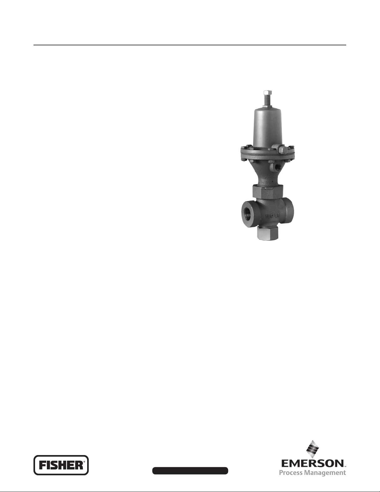
The Type 122A valve (see Figure 1) is a highcapacity, economical three-way pneumatic switching
valve for on-off applications. This valve can be
used for diverging or converging gaseous service,
diverging liquid service with gas-loaded liquids, and
converging liquid service. Six spring ranges are
available for control pressures from 3 to 150 psig
(0,21 to 10,3 bar).
Features
• Convenient Installation—Compact construction
permits easy handling and installation.
December 2009
• Easy Leak Detection—Vent hole between body
and actuator stem seals allows rapid detection of
body or actuator leakage.
• Easy Maintenance—With the bottom piping
disconnected, the valve can be completely
disassembled without removing it from the line.
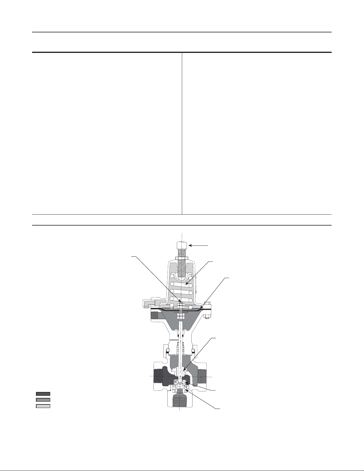
Principle of Operation
Refer to Figure 2. The ow through the Type 122A
valve is normally from port A to C, with the spring
force holding the valve plug down on port B
(diverging service).
As the pressure under the diaphragm is increased
through port D, it acts against the force of the spring.
When the control pressure overcomes the force of
the spring, the valve begins to stroke, opening port B.
Once the pressure under the diaphragm reaches
setpoint plus build-up, the valve completes its stroke
and the port C seat ring is closed. The valve will only
fully stroke when build-up above setpoint is achieved.
The point at which the valve completes its stroke
and the pressure change necessary to do this
are dependent on the spring rate and the setpoint
chosen. The set pressure is easily changed by
adjusting the screw at the top of the valve.
W3141-1*
Figure 1. Type 122A Three-Way Switching Valve
Installation
The Type 122A valve may be installed in any position.
Be certain the spring case vent opening is pointing
down and is protected against the entrance of the
moisture and any other material that may plug the
vent. The Type 122A valve should not be used in
installations where water hammer can be experienced.
Dimensions are shown in Figure 3.
Overpressure Protection
Type 122A Three-Way Switching Valves have
maximum outlet pressure ratings that are lower than
their maximum inlet pressure ratings. A pressurerelieving or pressure-limiting device is needed if inlet
pressure can exceed the maximum outlet pressure
rating. Overpressuring any portion of a switching
valve or associated equipment may cause leakage,
www.sherregulators.com
D200075X012
Page 2
Bulletin 71.7:122A
INLET PRESSURE
OUTLET PRESSURE
ATMOSPHERIC PRESSURE
Specications
Body Sizes and End Connection Styles
Connections A and C: Available in 3/4 or 1 body
sizes with NPT end connections
Connection B: 3/4 NPT
Maximum Inlet Pressure
(1)
150 psig (10,3 bar)
Set Pressure Ranges
See Table 1
Maximum Control Pressure to Diaphragm
(1)
150 psig (10,3 bar)
Temperature Capabilities
(1)
-20° to 150°F (-29° to 66°C)
Construction Materials
Valve Body: Cast iron
Bottom Connector: Steel
Spring Case: Aluminum
Lower Diaphragm Case: Cast iron
Disk and Disk Holder Assembly: Nitrile (NBR)
and Aluminum or Nitrile (NBR) and Stainless steel
1. The pressure/temperature limits in this Bulletin and any applicable standard or code limitation should not be exceeded.
2. At an inlet pressure of 25 psig (1,7 bar) and with full pressure drop across the body.
Orice: Aluminum or Stainless steel
Diaphragm: Neoprene (CR)
Gaskets: Composition
O-Rings: Nitrile (NBR)
Washers: Zinc-plated steel and
302 Stainless steel
Spring: Zinc-plated steel
Flow Coefcients
(2)
C
g
Connection A to B: 138
Connection A to C: 131
C
1
Connection A to B: 28.0
Connection A to C: 32.5
Control Connection
1/4 NPT internal
Vent Connection
1/4 NPT internal with screen
Approximate Weight
5 pounds (2 kg)
W0157
INLET PRESSURE
OUTLET PRESSURE
ATMOSPHERIC PRESSURE
STEM
PORT D
PORT A
PORT B
ADJUSTING SCREW
SPRING
DIAPHRAGM
UPPER VAVE SEAT
PORT C
VALVE
LOWER VAVE SEAT
Figure 2. Type 122A Three-Way Switching Valve Operational Schematic
2
Page 3

Table 1. Set Pressure Ranges
Bulletin 71.7:122A
SET PRESSURE
RANGES
Psig bar Psig bar Inches mm Inches mm
3 to15
5 to 20
5 to 35
30 to 60
40 to 100
60 to 150
0,21 to 1,0
0,34 to 1,4
0,34 to 2,4
2,1 to 4,1
2,8 to 6,9
4,1 to 10,3
parts damage, or personal injury due to bursting of
PRESSURE BUILD-UP
ABOVE SETPOINT
REQUIRED FOR
FULL STROKE
10
13.5
22
30
54
66
0,69
0,93
1,5
2,1
3,7
4,6
SPRING
PART
NUMBER
1D892327022
1D751527022
1D665927022
1D7455T0012
1E543627142
1P901327142
SPRING
COLOR
Red
Cadmium
Blue
Green
Yellow
Brown
SPRING WIRE DIAMETER SPRING FREE LENGTH
0.168
0.187
0.218
0.234
0.283
0.240
4,27
4,75
5,54
5,94
7,19
6,10
Ordering Information
2.94
2.81
2.50
2.57
2.31
2.63
pressure-containing parts or explosion of accumulated
gas. Switching valve operation within ratings does
not preclude the possibility of damage from external
sources or from debris in the pipeline. A switching
valve should be inspected for damage periodically and
after any overpressure condition.
Refer to the Specications section. Review the
description to the right of each specication and in
the referenced table and specify the desired choice
wherever there is a selection to be made. Also be
sure to specify the desired set pressure.
4.12 Ø
(105)
74,7
71,4
63,5
65,3
58,7
66,8
AR1545-A
A1164-1
VENT
1/4 NPT
CONTROL CONNECTION
3/4 OR 1 NPT
1.81
(46)
3.62
(92)
7.88 (MAX)
(200)
2.19
(56)
2.12
(54)
3/4 NPT
INCHES
(mm)
Figure 3. Dimensions
3
Page 4

Bulletin 71.7:122A
Ordering Guide
Body Size (Connections A and C) (Select One)
3/4 NPT
1 NPT
Quantity (Specify) __________
Disk and Disk Holder Assembly (Select One)
Nitrile (NBR) and Aluminum***
Nitrile (NBR) and Stainless steel***
Seat Rings (Select One)
Aluminum***
Stainless steel***
Set Pressure Range (Select One)
3 to 15 psig (0,21 to 1,0 bar), Red***
5 to 20 psig (0,34 to 1,4 bar), Cadmium***
5 to 35 psig (0,34 to 2,4 bar), Blue***
30 to 60 psig (2,1 to 4,1 bar), Green***
40 to 100 psig (2,8 to 6,9 bar), Yellow***
60 to 150 psig (4,1 to 10,3 bar), Brown***
Regulators Quick Order Guide
* * * Readily Available for Shipment
* * Allow Additional Time for Shipment
* Special Order, Constructed from Non-Stocked Parts. Consult
Your local Sales Ofce for Availability.
Availability of the product being ordered is determined by the component
with the longest shipping time for the requested construction.
Specication Worksheet
Application (Please designate units):
Specic Use
Line Size
Gas Type and Specic Gravity
Gas Temperature
Does the Application Require Overpressure Protection?
Yes No If yes, which is preferred:
Relief Valve Monitor Regulator Shutoff Device
Is overpressure protection equipment selection assistance
desired?
Pressure (Please designate units):
Maximum Inlet Pressure (P
Minimum Inlet Pressure (P
1max
1min
)
)
Downstream Pressure Setting(s) (P2)
Maximum Flow (Q
max
)
Performance Required:
Accuracy Requirements?
Need for Extremely Fast Response?
Other Requirements:
Industrial Regulators
Emerson Process Management
Regulator Technologies, Inc.
USA - Headquarters
McKinney, Texas 75069-1872 USA
Tel: 1-800-558-5853
Outside U.S. 1-972-548-3574
Asia-Pacic
Shanghai, China 201206
Tel: +86 21 2892 9000
Europe
Bologna, Italy 40013
Tel: +39 051 4190611
Middle East and Africa
Dubai, United Arab Emirates
Tel: +971 4811 8100
For further information visit www.sherregulators.com
The Emerson logo is a trademark and service mark of Emerson Electric Co. All other marks are the property of their prospective owners. Fisher is a mark owned by Fisher Controls, Inc., a
business of Emerson Process Management.
The contents of this publication are presented for informational purposes only, and while every effort has been made to ensure their accuracy, they are not to be construed as warranties or
guarantees, express or implied, regarding the products or services described herein or their use or applicability. We reserve the right to modify or improve the designs or specications of such
products at any time without notice.
Emerson Process Management does not assume responsibility for the selection, use or maintenance of any product. Responsibility for proper selection, use and maintenance of any Emerson
Process Management product remains solely with the purchaser.
Natural Gas Technologies
Emerson Process Management
Regulator Technologies, Inc.
USA - Headquarters
McKinney, Texas 75069-1872 USA
Tel: 1-800-558-5853
Outside U.S. 1-972-548-3574
Asia-Pacic
Singapore, Singapore 128461
Tel: +65 6777 8211
Europe
Bologna, Italy 40013
Tel: +39 051 4190611
Gallardon, France 28320
Tel: +33 (0)2 37 33 47 00
TESCOM
Emerson Process Management
Tescom Corporation
USA - Headquarters
Elk River, Minnesota 55330-2445 USA
Tel: 1-763-241-3238
Europe
Selmsdorf, Germany 23923
Tel: +49 (0) 38823 31 0
©Emerson Process Management Regulator Technologies, Inc., 1980, 2009; All Rights Reserved
 Loading...