


EMCO WinNC SINUMERIK 810/820 M
Software Description/ Software Version from 13.70
S I E M E N S |
SINUMERIK |
|
|
|
|
|
|
|
% |
/ |
N |
G |
|
|
|
|
|
|
|
|
7 |
8 |
9 |
|
|
|
|
|
|
|
|
|
X |
C |
Z |
4 . |
@ |
|
|
|
|
|
|
|
4 |
5 |
6 |
|
* |
|
|
|
|
|
|
|
I |
J |
K |
U |
A |
|
|
|
|
|
|
|
1 |
2 |
3 |
|
- |
|
|
|
|
|
|
|
F |
D |
L |
P |
R |
|
|
|
|
|
|
|
+/- |
0 |
. |
= |
+ |
|
|
|
|
|
|
|
M |
S |
T |
H |
L F |
|
|
|
|
|
|
|
|
|
|
1 . n |
|
GESFanucI E M ESeriesN 21 |
|
|
|
|
SINUMERIK |
|
|
|
|
|
|
< |
|
|
|
|
|
> |
USB |
|
|
RS232 |
|
|
|
|
|
|
|
|
|
||||
SKIP |
DRY |
-4 |
+Z |
|
+Y |
|
1 |
|
|
60 7 0 |
80 |
|
RUN |
|
|
|
|
|
10 |
|
40 |
|
90 |
1 x |
STOPOPT. |
-X |
|
|
+X |
|
100 |
|
2 0 |
|
100 |
|
|
|
|
|
|
|
1000 |
|
10 |
|
|
|
SBL |
-Y |
-Z |
|
+4 |
|
EDIT |
|
6 |
|
110 |
|
|
|
10000 |
|
2 |
|
|
||||
|
|
|
|
|
100% |
|
|
|
0 |
|
120 |
|
|
|
|
|
|
|
|
|
|
|
|
|
|
|
|
|
AUX |
AUX |
|
|
|
|
|
|
|
|
0 |
|
0 |
|
|
|
|
|
|
|
|
|
|
1 |
1 |
|
|
|
|
|
|
S I E M E N S
<
SINUMERIK
>
S I E M E N S |
|
|
|
|
|
SINUMERIK |
||
% |
A |
B |
C |
D |
E |
F |
G |
H |
I |
J |
K |
L |
M |
N |
O |
P |
Q |
R |
S |
T |
U |
V |
W |
X |
Y |
Z |
|
|
: |
= |
@ |
( |
) |
|
LF |
|
|
|
|
7 |
8 |
9 |
|
|
|
|
|
|
4 |
5 |
6 |
|
* |
|
|
|
|
1 |
2 |
3 |
|
- |
1...n |
|
|
|
+/- |
0 |
. |
|
+ |
|
|
|
|
|
||||
USB
 RS232
RS232
SKIP |
DRY |
-4 |
+Z |
|
+Y |
1 |
60 70 |
80 |
|
RUN |
|
|
|
|
10 |
40 |
90 |
1 x |
STOPOPT. |
-X |
|
|
+X |
100 |
20 |
100 |
|
|
|
|
|
|
1000 |
10 |
|
|
SBL |
-Y |
-Z |
|
+4 |
EDIT |
6 |
110 |
|
|
10000 |
2 |
|
||||
|
|
|
|
|
1 0 0 % |
|
0 |
120 |
|
|
|
|
|
|
|
|
|
|
|
|
|
|
AUX |
AUX |
|
|
|
|
|
0 |
|
0 |
|
|
|
|
|
|
|
1 |
1 |
|
|
|
Software Description
EMCO WinNC SINUMERIK 810/820 M
Ref.No. EN 1803 |
Edition J2003-10 |
EMCO Maier Ges.m.b.H.
P.O. Box 131
A-5400 Hallein-Taxach/Austria Phone ++43-(0)62 45-891-0 Fax ++43-(0)62 45-869 65 Internet: www.emco.at
E-Mail: service@emco.co.at

EMCO WINNC SINUMERIK 810/820 M |
PREFACE |
Preface
The EMCO WinNC SINUMNERIK 810/820 M Milling Software is part of the
EMCO training concept on PC-basis.
This concept aims at learning the operation and programming of a certain machine control on the PC.
The milling machines of the EMCO PC MILL und CONCEPT MILL series can be directly controlled via PC by means of the EMCO WinNC for the EMCO MILL.
The operation is rendered very easy by the use of a digitizer or the control keyboard with TFT flat panel display (optional accessory), and it is didactically especially valuable since it remains very close to the original control.
This manual does not include the whole functionality of the control software SINUMNERIK 810/820 M Milling, however emphasis was laid on the simple and clear illustration of the most important functions so as to achieve a most comprehensive learning success.
In case any questions or proposals for improving this manual should arise, please contact us directly:
EMCO MAIER Gesellschaft m. b. H.
Department for technical documentation
A-5400 Hallein, Austria
All rights reserved, reproduction only by authorization of Messrs. EMCO MAIER © EMCO MAIER Gesellschaft m.b.H., Hallein 2003
2

EMCO WINNC SINUMERIK 810/820 M |
CONTENTS |
Contents
A: Key Description
Control Keyboard, Digitizer Overlay ..................................... |
A1 |
Key Functions .................................................................... |
A2 |
Address and Numeric Keyboard ......................................... |
A2 |
Machine Control Keys ........................................................ |
A4 |
PC Keyboard ..................................................................... |
A6 |
Screen with Softkeys .......................................................... |
A7 |
B: Basics
Reference Points of the EMCO Milling Machines ................. |
B1 |
Zero offset ......................................................................... |
B2 |
Coordinate System ............................................................. |
B2 |
Coordinate System with Absolute Programming ............. |
B2 |
Coordinate System with Incremental Programming ........ |
B2 |
Input of the Zero Offset ....................................................... |
B3 |
Input of the Coordinate Rotation ......................................... |
B3 |
Tool Data Measuring .......................................................... |
B4 |
Input of Tool Data ............................................................... |
B5 |
Tool Data Measuring with a Metering Clockwork |
|
or a Measuring Cell ............................................................ |
B6 |
C: Operating Sequences
Survey Modes ................................................................... |
C1 |
Approach the Reference Point ........................................... |
C2 |
Input of the Gear Position .................................................. |
C2 |
Setting of Language and |
|
Workpiece Directory .......................................................... |
C2 |
Input of Programs ............................................................. |
C3 |
Program Input with Guiding Function ............................ |
C4 |
Program Input with CAD/CAM Systems ........................ |
C4 |
Data Input-Output ............................................................. |
C5 |
Program Administration ..................................................... |
C5 |
Copy Program ............................................................. |
C5 |
Rename Program ........................................................ |
C5 |
Delete Program........................................................... |
C5 |
Data Input via COM1 / COM2 ...................................... |
C6 |
Data Import ................................................................. |
C6 |
Data Output ................................................................ |
C7 |
Print Data ................................................................... |
C7 |
Adjusting the Serial Interface ....................................... |
C8 |
Program Run .................................................................... |
C9 |
Start of a Part Program ................................................ |
C9 |
Messages while Program Run ..................................... |
C9 |
Program Influence ....................................................... |
C9 |
Overstore .................................................................. |
C10 |
Block Search ............................................................. |
C10 |
Program Interruption .................................................. |
C10 |
Status Display of the PLC ........................................... |
C10 |
Display of the Software Versions ................................. |
C10 |
Graphic simulation ........................................................... |
C11 |
D: Programming
Program Structure ............................................................. |
D1 |
|
Used Addresses ................................................................ |
D1 |
|
Survey of M commands ..................................................... |
D2 |
|
Survey of cycles ................................................................ |
D2 |
|
Command Description GCommands ................................. |
D3 |
|
G00 |
Rapid Traverse .......................................................... |
D3 |
G01 |
Linear Interpolation .................................................... |
D3 |
G02 |
Circular Interpolation Clockwise .................................. |
D4 |
G03 |
Circular Interpolation Counterclockwise ....................... |
D4 |
Helix Interpolation ............................................................. |
D4 |
|
G04 |
Dwell ......................................................................... |
D5 |
G09 |
Exact Stop ................................................................. |
D5 |
G10 |
- G13 Polar Coordinate Interpolation ........................... |
D5 |
G17-G19 Plane Selection .................................................. |
D6 |
|
G25/G26 Programmierbare Arbeitsfeldbegrenzung .......... |
D6 |
|
G33 |
Thread Cutting ........................................................... |
D7 |
Cutter Radius Compensation ............................................. |
D8 |
|
G40 |
Cancel Cutter Radius Compensation .......................... |
D8 |
G41 |
Cutter Radius Compensation Left ............................... |
D8 |
G42 |
Cutter Radius Compensation Right ............................. |
D8 |
G48 |
Leave as Approached .............................................. |
D10 |
G50 |
Cancel Scale Modification ........................................ |
D10 |
G51 |
Scale Modification .................................................... |
D10 |
G53 |
Cancel Zero Offset Blockwise .................................... |
D11 |
G54 - G57 Zero Offset 1 - 4 / Coordinate Rotation 1-4 ........ |
D11 |
|
G58/G59 Programmable Zero Offset / Coordinate Rotation D11 |
||
G60 |
Exact Stop Mode...................................................... |
D12 |
G62,G64 Deselection Exact Stop Mode ............................ |
D12 |
|
G70 |
Measuring in Inch .................................................... |
D12 |
G71 |
Measuring in Millimeter ............................................ |
D12 |
G80 |
Delete G81 bis G89 ................................................. |
D13 |
G81 |
Call Cycle L81 ......................................................... |
D13 |
G82 |
Call Cycle L82 ......................................................... |
D13 |
G83 |
Call Cycle L83 ......................................................... |
D13 |
G84 |
Call Cycle L84 ......................................................... |
D13 |
G85 |
Call Cycle L85 ......................................................... |
D13 |
G86 |
Call Cycle L86 ......................................................... |
D13 |
G87 |
Call Cycle L87 ......................................................... |
D13 |
G88 |
Call Cycle L88 ......................................................... |
D13 |
G89 |
Call Cycle L89 ......................................................... |
D13 |
G90 |
Absolute Programming ............................................. |
D13 |
G91 |
Incremental Programming ........................................ |
D13 |
G 92 Cylindrical interpolation .......................................... |
D14 |
|
G94 |
Feed Rate in Minutes ............................................... |
D15 |
G95 |
Feed Rate in Revolutions ......................................... |
D15 |
G147 Soft Approach to Contour with Linear ...................... |
D16 |
|
G247 Soft Approach to Contour with Quarter Circle ........... |
D16 |
|
G347 Soft Approach to Contour with Semicircle ................ |
D16 |
|
G148 Soft Leaving the Contour with Linear ....................... |
D16 |
|
G248 Soft Leaving the Contour with Quarter Circle ........... |
D16 |
|
G348 Soft Leaving the Contour with Semicircle ................. |
D16 |
|
3

EMCO WINNC SINUMERIK 810/820 M |
CONTENTS |
Description of M Commands ............................................. |
D17 |
|
M00 |
Programmed Stop .................................................... |
D17 |
M01 |
Programmed Stop, Conditional .................................. |
D17 |
M02 |
Main Program End .................................................... |
D17 |
M03 |
Milling Spindle ON Clockwise .................................... |
D17 |
M04 |
Milling Spindle ON Counterclockwise ......................... |
D17 |
M05 |
Milling Spindle OFF .................................................. |
D17 |
M06 Tool Change ............................................................. |
D17 |
|
M08 |
Coolant ON .............................................................. |
D17 |
M09 |
Coolant OFF ............................................................ |
D17 |
M17 |
Subroutine End ........................................................ |
D17 |
M27 |
Swivel Dividing Head ................................................ |
D17 |
M30 |
Main Program End .................................................... |
D17 |
M53 |
- M58 Mirror Functions .............................................. |
D18 |
M71 |
Puff Blowing ON ....................................................... |
D18 |
M72 |
Puff Blowing OFF ..................................................... |
D18 |
Description of Cycles ........................................................ |
D19 |
|
L81 Drilling, Centering ...................................................... |
D20 |
|
L82 Drilling, Spot Facing ................................................... |
D20 |
|
L83 Deep-hole Drilling ...................................................... |
D21 |
|
L84 Thread Tapping with/without Encoder ......................... |
D22 |
|
L85 Boring 1 .................................................................... |
D23 |
|
L86 Boring 2 .................................................................... |
D23 |
|
L87 Boring 3 .................................................................... |
D24 |
|
L88 Boring 4 .................................................................... |
D24 |
|
L89 Boring 5 .................................................................... |
D24 |
|
L96 Cycle for Tool Change ................................................ |
D25 |
|
Drilling and Milling Patterns .............................................. |
D25 |
|
L900 Drilling Pattern Hole Circle ....................................... |
D26 |
|
L901 Milling Pattern Slot ................................................... |
D26 |
|
L902 Milling Pattern Elongated Hole ................................. |
D27 |
|
L903 Milling Rectangular Pocket ....................................... |
D27 |
|
L904 Milling Pattern Circular Slot ...................................... |
D28 |
|
L905 Drilling Pattern Single Hole ...................................... |
D28 |
|
L906 Drilling Pattern Row of Holes .................................... |
D29 |
|
L930 Milling Pattern Circular Pocket .................................. |
D29 |
|
L999 Clear Buffer Memory ................................................ |
D30 |
|
Contour Definition ............................................................ |
D31 |
|
Insert Chamfer ........................................................... |
D31 |
|
Insert Radius ............................................................. |
D31 |
|
Line ........................................................................... |
D31 |
|
Arc ............................................................................ |
D31 |
|
Line - Line ................................................................. |
D32 |
|
Line - Arc (tangential) ................................................. |
D32 |
|
Arc - Line (tangential) ................................................. |
D32 |
|
Arc - Arc (tangential) ................................................... |
D32 |
|
Subroutines ..................................................................... |
D33 |
|
Subroutine Call in Part Program .................................. |
D33 |
|
Subroutine End with M17 ............................................ |
D33 |
|
Subroutine Nesting ..................................................... |
D33 |
|
E: @-Codes |
|
|
G: Survey Pages |
|
|
Survey Softkey Explanations .............................................. |
G1 |
|
Softkey Menu Survey ........................................................ |
G6 |
|
Survey Guiding ................................................................. |
G8 |
|
H: Alarms and Messages |
|
|
Startup Alarms .................................................................. |
H1 |
|
Control Alarms .................................................................. |
H3 |
|
Machine Alarms ............................................................... |
H10 |
|
Starting Information
see attachment
4

EMCO WINNC SINUMERIK 810/820 M |
KEY DESCRIPTION |
A: Key Description
Control Keyboard, Digitizer Overlay
|
|
|
|
|
|
6,(0 (16 |
|
|
|
|
6,180(5,. |
|||
|
|
|
|
|
|
|
|
|
|
1 |
* |
|
|
|
|
|
|
|
|
|
|
|
|
|
|
|
|
|
|
|
|
|
|
|
|
|
|
; |
& |
= |
|
# |
|
|
|
|
|
|
|
|
|
|
|
|
|
|
|
|
|
|
|
|
|
|
|
|
|
, |
- |
. |
8 |
$ |
|
|
|
|
|
|
|
|
|
|
|
|
|
|
|
|
|
|
|
|
|
|
|
|
|
) |
' |
/ |
3 |
5 |
|
|
|
|
|
|
|
|
|
|
|
|
|
|
|
|
|
|
|
|
|
|
|
|
|
0 |
6 |
7 |
+ |
/ ) |
|
|
|
|
|
|
|
|
|
|
|
|
|
Q |
|
|
|
*( )DQXF,(0 6HULHV16 |
|
|
|
|
6,180(5,. |
|
|
|
|
|
|
|
|
|
|
|
|
|
|
|
|
|
86% |
|
56 |
|
|
||
6.,3 |
'5< |
|
|
|
|
|
|
|
|
|
|
|
|
|
581 |
|
= |
|
< |
|
|
|
|
|
|
|
|||
|
|
|
|
|
|
|
|
|
|
|
|
|
|
|
[ |
237 |
; |
|
|
; |
|
|
|
|
|
|
|
|
|
6723 |
|
|
|
|
|
|
|
|
|
|
|
|||
|
|
|
|
|
|
|
|
|
|
|
|
|
|
|
|
|
|
|
|
|
(',7 |
|
|
|
|
|
|
|
|
|
6%/ |
|
|
|
|
|
|
|
|
|
|
|
||
|
< |
= |
|
|
|
|
|
|
|
|
|
|
|
|
|
|
|
|
|
|
|
|
|
|
|
|
|
|
|
|
|
|
|
|
|
|
|
|
|
|
|
|
|
|
|
|
|
|
|
|
|
|
|
|
|
|
|
|
|
|
|
|
|
|
$8; |
$8; |
|
|
|
|
|
|
|
|
|
|
|
|
|
|
|
|
|
|
|
|
|
|
|
|
|
|
|
|
|
|
|
|
|
|
|
|
|
|
|
|
|
|
|
|
|
|
|
|
|
|
|
|
|
|
|
|
|
|
|
|
|
|
|
|
|
|
|
|
|
|
|
|
|
|
6,(0 (16 |
|
|
|
|
6,180(5,. |
|||
|
|
|
|
|
|
|
$ |
% |
& |
' |
( |
) |
* |
+ |
|
|
|
|
|
|
, |
- . |
/ |
0 |
1 |
2 |
3 |
4 |
|
|
|
|
|
|
|
5 |
6 |
7 |
8 |
9 |
: |
; |
< |
= |
|
|
|
|
|
|
|
|
|
|
# |
|
|
|
/) |
|
|
|
|
|
|
|
|
|
|
|
|
|
|
|
|
|
|
|
|
|
|
|
|
|
|
|
|
|
|
|
|
|
|
|
|
|
|
|
|
|
|
|
|
|
|
|
|
|
|
|
|
|
|
|
|
|
|||
|
|
|
|
|
|
Q |
|
|
|
|
|
|
|
|
|
|
|
|
|
|
|
|
|
|
|
||||
6,(0 (16 |
|
|
|
|
|
6,180(5,. |
|
|
|
|
|
|
|
|
|
|
|
|
|
|
! |
|
86% |
|
56 |
|
|
||
|
|
|
|
|
|
|
|
|
|
|
||||
6.,3 |
'5< |
|
|
|
|
|
|
|
|
|
|
|
|
|
581 |
|
= |
|
< |
|
|
|
|
|
|
|
|||
|
|
|
|
|
|
|
|
|
|
|
|
|
||
|
|
|
|
|
|
|
|
|
|
|
|
|||
[ |
237 |
; |
|
|
; |
|
|
|
|
|
|
|
|
|
6723 |
|
|
|
|
|
|
|
|
|
|
|
|||
|
|
|
|
|
|
|
|
|
|
|
|
|
|
|
|
|
|
|
|
|
(',7 |
|
|
|
|
|
|
|
|
|
6%/ |
|
|
|
|
|
|
|
|
|
|
|
||
|
< |
= |
|
|
|
|
|
|
|
|
|
|
|
|
|
|
|
|
|
|
|
|
|
|
|
|
|
|
|
|
|
|
|
|
|
|
|
|
|
|
|
|
|
|
|
|
|
|
|
|
|
|
|
|
|
|
|
|
|
|
|
|
|
|
$8; |
$8; |
|
|
|
|
|
|
|
|
|
|
|
|
|
|
|
|
|
|
|
|
|
|
|
|
|
|
|
|
|
|
|
|
|
|
|
|
|
|
|
|
|
|
|
|
|
|
|
|
|
|
|
|
|
|
|
|
|
|
|
|
|
|
|
|
|
|
|
|
|
|
|
|
|
A 1 |
|
|
|
|
|
|
|
|
|

EMCO WINNC SINUMERIK 810/820 M |
KEY DESCRIPTION |
|
|
1 |
* |
|
|
|
|
|
# |
; |
& |
= |
4 |
|
|
|
|
|
|
, |
- |
. |
% |
$ |
|
|
|
|
|
) |
' |
/ |
3 |
5 |
|
|
|
|
|
0 |
6 |
7 |
+ |
/ ) |
AddressandnumerickeyboardoftheSINUMERIK
810 M
Key Functions
Inputkey
Deleteinput/operatormessage
Deleteword/block
Alterword
Searchaddress/block/word
Cursorup/down
Cursor left / right
Pageup/down
Acknowledgealarm
Actualpositionindoublesizeletters
Address and Numeric Keyboard
SINUMERIK 810M:
With the SHIFT key (at the top right edge) you can selectthesecondkeyfunction.
Pressing again this key selects the first function again.
AfterinputofaNCaddress(letter)theSHIFTfunctions isactiveautomatically
. functionK
.function6
SINUMERIK 820M:
Every address or number has its own key.
A 2

EMCO WINNC SINUMERIK 810/820 M |
KEY DESCRIPTION |
A 3
EMCO WINNC SINUMERIK 810/820 M |
KEY DESCRIPTION |
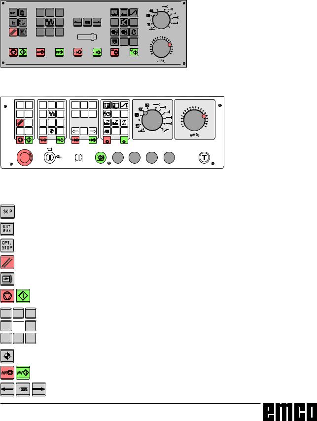
Machine Control Keys
Themachinekeysareinthelowerpartofthecontrol keyboardordigitizeroverlay.
Dependingontheusedmachineandaccessorynot allofthesefunctionsareactive.
|
|
|
|
|
|
|
; 4 |
|
|
|
|
|
(',7 |
|
= |
= |
|
4 |
; |
|
|
|
|
|
|
|
|
|
|
|
|
|
|
|
|
|
|
|
|
|
|
Machinecontrolkeyboard
6.,3 |
'5< |
|
= |
|
< |
|
|
|
581 |
|
|||||||
|
|
|
|
|
|
|
|
|
|
|
|
|
|
|
|
|
|
[ |
237 |
|
|
|
|
|
|
|
6723 |
; |
|
|
; |
|
|
|
|
|
|
|
|
|
|
|
|
|
|
|
|
|
|
|
(',7 |
|
|
|
6%/ |
|
|
|
|
|
||
|
< |
= |
|
|
|
|
|
|
|
|
|
|
|
|
|
|
|
|
|
|
|
|
|
|
|
|
|
|
|
|
|
|
|
|
|
|
|
|
|
|
$8; |
$8; |
|
|
|
|
|
|
|
|
|
|
|
|
|
|
|
|
|
|
|
|
|
|
|
|
|
|
|
|
|
|
|
|
|
|
|
|
|
MachinecontrolkeyboardoftheEMCOPC-MillSerie
= <
;  ;
;
< =
SKIP (skip blocks will not be executed)
DRY RUN (test run of programs) OPT STOP (program stop at M01) R E S E T
Singleblockmachining
Programstop/programstart
manualaxismovement
Approachingthereferencepointinallaxes
Feedstop/feedstart
Spindleoverridelower/100%/higher
A 4

EMCO WINNC SINUMERIK 810/820 M |
KEY DESCRIPTION |
(',7
|
|
|
|
|
|
|
|
|
|
|
|
|
|
|
|
|
|

Spindelstop/spindlestart;spindlestartinJOGandINC1...INC10000mode: Clockwise: perss  key short, Counterclockwise: press
 min. 1 sec. Open/closedoor
Swiveldividinghead
Open/closeclampingdevice
Swiveltoolturret
Coolanton/off
AUX OFF / AUX ON (auxiliary drives off / on)
Modeselector
Feed/rapidfeedoverrideswitch
EMERGENCY OFF (Unlock: pull out button)
Keyswitchforspecial operations(sieheMaschinenbeschreibung)
AdditionalNCstartkey
Additionalkeyclampingdevice
Consentkey
Nofunction
A 5

EMCOWINNC SINUMERIK 810/820 M |
KEYDESCRIPTION |
|
|
PC Keyboard
|
|
|
|
! |
|
|
1& |
|
|
|
|
|
|
|
|
|
|
|
|
||
|
|
|
|
|
|
|
|
|
|
|
|
|
|
|
|
|
|
|
|
|
|
|
|
|
|
+X |
|
|
|
|
||
|
|
|
|
|
|
|
||||
|
|
|
|
|
|
|
|
|
|
|
|
|
|
|
|
|
|
|
|
||
|
|
|
|
|
|
|
|
+Z |
|
|
|
|
||
|
|
|
|
|
|
|
|
||
|
|
|
|
|
|
|
|
|
|
|
|
|
||
|
|
|
|
X - |
|
|
|
|
|
|
|
|
|
|
|
|
|
|
|
Z |
|
|
|
|
||
|
- |
|
|
|
|
|
|
|
|
|
|
|
|
|
|
|
|
|
|
|
|
||
|
|
|
|
|
|
|
|
! |
|
! |
|
|
|
|
|
|
|
|
|
|
|
|
|
|
|
|
|
|
|
|
|
|
|
|
|
|
|
|
|
|
|
|
|
|
|
|
|
|
|
|
|
|
|
|
|
|
|
|
|
|
|
|
|
|
|
|
|
|
C • |
|
|
|
|
|
|
|
|
" ‰ |
|
|
||
|
|
|
|
|
|
|
|
|
|
|
|
|
|
|
|
|
|
|
|
|
|
|
||
|
|
|
|
|
|
|
8 |
|
|
|
|
|
||
|
|
|
|
|
|
|
|
||
|
|
|
|
|
|
|
|
|
|
|
|
|
|
|
|
|
|
|
|
|
|
|
|
|
|
|
|
||
|
|
|
|
|
|
|
|
|
|
|
|
|
|
|
|
|
|
|
|
|
|
|
|
|
|
|
|
|
|
|
|
|
||
|
|
|
|
|
|
|
|
|
|
|
|
|
|
|
|
|
|
|
|
|
|
|
|
|
|
|
|
|
|
|
|
|
||
|
|
|
||
|
|
|
|
|
|
|
|
|
|
|
|
|
|
|
|
|
|
|
|
|
|
# |
|
|
|
|
|||
|
|
|
|
|
|
|
|
|
|
|
|
|
|
|
|
|
|
|
|
|
|
|
|
|
|
|
|
||
|
|
|
|
|
|
ƒ A |
|
|
|
& ' |
|
% |
|
|
4 |
3 |
|
$ |
2 |
1 |
|
# |
|
/ |
0 |
" |
|
|
. |
! |
|
|
- |
|
, |
|
+ |
|
|
|
* |
|
)
(
5 6
7
7
|
|
The machine functions in |
the numeric key block are active only with active NUM |
lock. |
|
|
|
|
F12Withthe function keys PRESET, MDI- |
AUTOM.,JOG, REPOS, AUTOMATIC and POINTREF will be displayed in the softkey |
line. |
|
|
|
|
|
|
|
|
|
|
|
|
|
|
|
|
|
|
|
|
|
|
|
|
|
|
|
|
|
|
|
|
|
|
|
|
|
|
|
|
|
|
|
|
|
|
|
|
|
|
|
|
|
|
|
|
|
|
|
|
|
|
|
|
|
|
|
|
|
|
|
|
|
|
|
|
|
|
|
|
|
* |
|
|
|
|
|
|
|
|
|
|
|
|
|
acknowledgedbewillalarmsSomewith the key ESC. |
modestheF1keythepressingBy (JOG, AUTOMATIC,...) will be |
line.softkeytheindisplayed |
functionsaccessorytheofassignementThe is described int the chapter Functions"."Accessory |
combinationkeytheofmeaningThectrl 2 depends on the machine: 50/55:MILLPCEMCOPuff blowing ON/OFF 100/125/155:MILLPCEMCOcoolant ON/OFF |
|
||||||
|
|
|
|
|
|
|
|
|
|
|
|
|
|
|
7 |
|
|
|
|
|
|
|
|
|
|
|
|
|
|
|
|
|
|
|
A 6
EMCO WINNC SINUMERIK 810/820 M |
KEY DESCRIPTION |
Screen with Softkeys
|
|
|
|
|
|
|
|
:LQ1& 6LQXPHULN 7 F (0&2 |
|
|
|
|
[ |
6,(0(16 |
|
|
|
|
6,180(5,. |
|
|
|
|
|
|
|
|
Attheoperatingfieldthefollowingpartsaredefined:
1Displayofthemode
2Displayoftheoperatingconditions
3Displayofalarmnumber,text(comment)
4Displayofnotestotheoperator
5Displayofinputsfromthekeyboard
6Displayofthechannelnumber
7Displayofthesoftkeyfunctions
8Key"jumpbacktoahigherlevelmenu"(key F2at thePC)
9Softkeys (keys F3 - F7 at the PC)
10Key "Further functions in the same menu" (key F11 at the PC)
Softkeys (9) are keys with multiple meaning. The validmeaningwillbedisplayedatthebottomline(7) ofthescreen.
Screenwithsoftkeys
A 7

EMCO WINNC SINUMERIK 810/820 M |
KEY DESCRIPTION |
A 8
EMCO WINNC SINUMERIK 810/820 M |
BASICS |
B: Basics
|
1 |
0 |
|
: |
5 |
|
Referencepointsintheworkingarea
Reference Points of the EMCO
Milling Machines
M = Machine zero point
Anunchangeablereferencepointestablishedbythe machinemanufacturer.
Proceeding from this point the entire machine is measured.
Atthesametime"M"istheoriginofthecoordinate system.
R = Reference point
A position in the machine working area which is determinedexactlybylimitswitches.Theslidepositions are reported to the control by the slides approachingthe„R“.
Requiredaftereverypowerfailure.
N = Tool mount reference point
Startingpointforthemeasurementofthetools.„N“ liesatasuitablepointonthetoolholdersystemand isestablishedbythemachinemanufacturer.
W = Workpiece zero point
Startingpointforthedimensionsinthepartprogram. Canbefreelyestablishedbytheprogrammerand movedasdesiredwithinthepartprogram.
B 1

EMCO WINNC SINUMERIK 810/820 M |
BASICS |
0 |
: |
ZerooffsetfrommachinezeropointMto workpiecezeropointW
|
= |
Incremental |
|
|
= |
< |
|
|
; |
; |
|
|
< |
= |
|
< |
Absolute |
|
|
= |
; |
|
|
; |
|
|
< |
Absolutecoordinatesrefertoafixedpoint,incrementalcoordinatestothetoolposition
Zero offset
WithEMCOmillingmachinesthemachinezeropoint "M"liesontheleftfrontedgeofthemachinetable. This position is unsuitable as a starting point for dimensioning. With the so-called zero offset the coordinatesystemcanbemovedtoasuitablepoint intheworkingareaofthemachine.
Inthesettingdatazerooffsetarefouradjustablezero offsetsavailable.
When you define a value in the offset register, this valuewillbeconsideredwithcallupinprogram(G54 -G57)andthecoordinatezeropointwillbeshifted fromthemachinezeroMtotheworkpiecezeroW.
The workpiece zero point can be shifted within a program with "G58, G59 - programmable zero offset" in any number.
MoreinformationsseeincommanddescriptionG58, G59.
Coordinate System
TheXcoordinateliesparalleltothefrontedgeofthe machinetable,theYcoordinateliesparalleltothe sideedgeofthemachinetable,theZcoordinateis verticaltothemachinetable.
Z coordinate values in minus direction describe movementsofthetoolsystemtowardstheworkpiece, valuesinplusdirectionawayfromtheworkpiece.
Coordinate System with Absolute Programming
Theoriginofthecoordinatesystemliesinthemachine zeropoint"M"orafterazerooffsetintheworkpiece zero point "W".
Alltargetpointsaredescribedfromtheoriginofthe coordinatesystembyindicationoftherespectiveX, Y and Z distances.
Coordinate System with Incremental Programming
The origin of the coordinate system lies at the tool mountreferencepoint"N"oratthetooltipafteratool call-up.
Withincrementalprogrammingtheactualpathesof thetool(frompointtopoint)aredescribed.
B 2

EMCO WINNC SINUMERIK 810/820 M |
BASICS |
:LQ1& 6LQXPHULN 0 F (0&2 |
|
|
[ |
|
|
|
$8720$7,&
6(77,1*'$7$ =(52 2))6(7 *
=(52 2))6(7 |
=(52 2))6(7 $'',7,9( |
||
; |
|
; |
|
< |
|
< |
|
= |
|
= |
|
* ) |
* ) |
* ) |
* ) |
) |
|
|
|
|
|
InputpatternforzerooffsetG54
Input of the Zero Offset
Fourzerooffsetscanbeentered(e.g.forfourdifferentclampingdevices).
•Press the softkey SETTING DATA in any mode.
•Press the softkey ZERO OFFSET.
•Thescreenshowstheinputpatternforzerooffset G54. The particular offsets G54 - G57 can be selectedwithsoftkeys.
•BelowZEROOFFSETthemeasuredvalues(e.g.: X,Y,Z=distancemachinezeropoint-workpiece zeropoint)areentered.
•Correctionstothisvaluescanbeenteredbelow ZO ADDIT.. These corrections will be added.
•MovetheCursortothevaluetobealteredwiththe
keys |
. |
•Enternewvalueandpressthekey .
.
•The inverse input mark jumps to the next input field.
:LQ1& 6LQXPHULN 0 F (0&2 |
|
|
[ |
|
|
|
-2* 6(77,1*'$7$ &225',1$7( 527$7,21
$ |
|
* |
$ |
|
* |
$ |
|
* |
$ |
|
* |
$ |
|
* |
$ |
|
* |
) |
) |
) |
) |
) |
|
|
|
|
|
Inputpatternforcoordinaterotation
Input of the Coordinate Rotation
Acoordinaterotationcanbeprogrammedforevery zerooffset.Thiscoordinaterotationbecomesactive withcallingupthezerooffset.
•Press the softkey SETTING DATA in any mode.
•Extendthesoftkeyline(key ! )andpressthe softkey ROTAT. ANGLE.
•The screen shows the input pattern for the coordinaterotation.ThesinglerotationsforG54 -G57canbeenteredinthispattern,therotations forG58andG59willbedeterminedintheCNC program.
•Movethecursortothevaluetobealteredwiththe keys 


 .
.
•Enterthenewvalueandpressthekey .
.
•The inverse input mark jumps to the next input field.
B 3

EMCO WINNC SINUMERIK 810/820 M |
BASICS |
 1
1
=
Lengthcorrection
5 5
Cutter radius R
1 |
1 |
/ |
/ |
|
5 |
W\SH |
W\SH |
Tooltype
Tool Data Measuring
Aimofthetooldatameasuring:
Thecontrolshouldusethetooltiporthetoolcentre pointforpositioning,notthetoolmountreference point.
Every tool which is used for machining has to be measured.Thedistancebetweentooltipandtool mountreferencepointistobemeasured.
In the so-called tool register the measured length corrections,thecutterradiusandthecutterposition canbestored.
Every tool offset number D1 - D99 is related to a tool.
Thecorrectionnumbercanbeanyregisternumber, buthastobeconsideredwithtoolcallinprogram.
Example
Thelengthcorrectionsofatoolintetoolturretstation 4havebeenstoredascorrectionnumber41.
Toolcallinprogram: |
T4 |
D41 L96 |
or: |
T4 D41 M6 |
|
The address T marks the position in the tool turret, theaddressDmarksthecorrectionnumberbelonging toit.ThecycleL96includestheexecutionofthetool change(dependingonthemachine)intheprogram. UsethecommandM6,ifyouwanttochangethetool with OVERSTORE.
Inserting cutter radius is only necessary for using cutter radius compensation with this tool.
ForactiveX-Yplane(G17):
Thetooldatameasuringoccursfor:
L1: inZdirectionabsolutefrompoint"N"
R:cutterradius
Type: cutter position 1 - 9
Thetooldatameasuringoccursfortype10:
L1: inZdirectionabsolutefrompoint"N"
Type: drilling tool 10, milling tool 20
ForallotheractiveplanesL1isalwayscalculatedas verticalaxistotheactiveplane.
InthefollowingthecommoncaseG17isdescribed.
With "WEAR" occurs the correction of not exact measured tool data or of worn tools after several machiningruns.Theinsertedlengthwillbeaddedor subtractedfromthegeometryofthetoolincrementally.
L1 +/- .....Incremental
R +/- ......Incremental
B 4

EMCO WINNC SINUMERIK 810/820 M |
BASICS |
:LQ1& 6LQXPHULN 0 F (0&2 |
|
|
|
|
|
[ |
|
||||
|
|
|
|
|
|
|
|||||
$8720$7,& |
|
|
|
|
|
|
|
|
|
||
722/ 2))6(7 |
|
|
|
|
|
|
|
|
|
||
$FWXDO WRRO RIIVHW QR |
|
|
|
' |
|
|
|
|
|
||
' |
7RRO QXPEHU |
|
|
|
|
|
|
||||
|
7\SH |
|
|
|
|
|
|
|
|
||
|
/ *HRPHWU\ |
|
|
|
|
|
|
||||
|
/ *HRPHWU\ |
|
|
|
|
|
|
||||
|
'LDPHWHU 5DGLXV |
|
|
|
|
|
|
||||
|
/ :HDU |
|
|
|
|
|
|
|
|
||
|
/ :HDU |
|
|
|
|
|
|
|
|
||
|
'LDPHWHU 5DGLXV |
|
|
|
|
|
|
||||
|
/ %DVH |
|
|
|
|
|
|
|
|
||
|
/ %DVH |
|
|
|
|
|
|
|
|
||
|
|
|
|
|
|
|
|
|
|
|
|
|
) |
|
) |
|
) |
) |
|
|
) |
|
|
|
|
|
|
|
|
|
|
|
|
|
|
Inputpatternfortooldata
Input of Tool Data
Select the softkey TOOL OFFSET in any mode. Thescreenshowstheinputpatternfortooldata.
•Select the desired tool offset number with the keys and
and orbyentryofthecorrection numberandthekey"search"(e.g.
  ).
).
•Position the Cursor (invers mark) with the keys


 and
and  to the desired input field. Enterthedesiredvaluewiththenumerickeyboard. Theenteredvaluewillbeshownattheinputline ofthescreen.
•Storethecorrectionvaluewiththekey inthe tooloffsetregister.
Thecursorjumpstothenextinputpositionresp. afterinputofthelastvaluetothefirstvalueofthe nexttooloffsetnumber.
Additiveinputwith ,deletewith
 .
.
B 5

EMCO WINNC SINUMERIK 810/820 M |
BASICS |
1 |
1 |
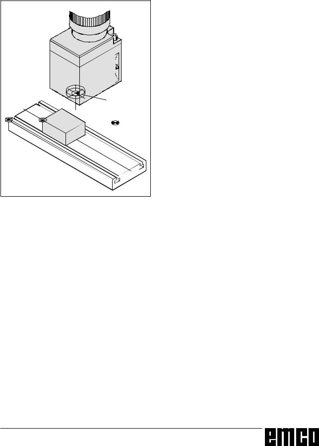
Traversewiththetoolmountreferencepointonto themeteringclockworkormeasuringcell
Tool Data Measuring with a MeteringClockwork
or a Measuring Cell
Sequence of operation
•Setupthemeteringclockworkorthemeasuring cellsointheworkingarea,thatthemeasuringpoint canbereachedwiththetoolmountreferencepoint andwithalltoolstobemeasured.
•ChangetothemodeJOG.
•Traversewiththetoolmountreferencepointonto themeteringclockworkandsetittozeroorontothe measuringcelluntilthelamplightsup.
•NotethefirstZvalue(Z1),whichisdisplayedatthe screen.
Note
AttheEMCOPCMILL100thetoolmountreference point is on the face centre of the reference tool. Clampthistoolforthesequencedescribedabove.
• Clampthetooltobemeasuredandtraversewithit ontothemeteringclockworkuntil0isdisplayedor ontothemeasuringcelluntilthelamplightsup.
• NotethesecondZvalue(Z2),whichisdisplayedat
thescreen.
• ThedifferenceZ2-Z1isthelengthcorrectionL1of
thetool.
• Insert L1 for the corresponding tool correction numberintotheinputpatternfortooldata.
• Insert tool type 10 or 20, for type 20 also the tool radius.
Traversewiththetooltipontothemetering
clockworkormeasuringcell
• Clampnexttoolandtraverseontothemetering clockworkormeasuringcelletc..
B 6

EMCO WINNC SINUMERIK 810/820 M |
OPERATING SEQUENCES |
C: Operating Sequences
Survey Modes
AUTOMATIC 
For working off a part program the control calls up block after block and interprets them.
The interpretation considers all corrections which are called up by the program.
The so-handled blocks will be worked off one by one.
JOG
With the JOG keys the tool can be traversed manually. In the submode OVERSTORE (softkey) you can switch on the spindle and swivel the tool holder.
REFPOINT
This mode is used to approach the reference point. With reaching the reference point the actual position store is set to the value of the reference point coordinates. By that the control acknowledges the position of the tool in the working area.
With the following situations the reference point has to be approached:
•After switching on the machine
•After mains interruption
•After alarm "Approach reference point" or "Ref.- point not reached".
•After collisions or if the slides stucked because of overload.
INC FEED 1 ... INC FEED 10 000
MDI-AUTOMATIC 
You can enter blocks of a part program in the intermediate store.
The control works off the inserted block and deletes the intermediate store for new entries.
1 ... 10000
In this mode the slides can be traversed for the desired increment (1 ... 10000 in µm / 10-4 inch) with
means of the JOG keys -X + X - Y +Y
-Z +Z .
The selected increment must be larger than the machine resolution (smallest possible traverse distance), otherwise no movement occurs.
C 1

EMCO WINNC SINUMERIK 810/820 M |
OPERATING SEQUENCES |
Approach the Reference Point
By approaching the reference point the control will be synchronized with the machine.
•Select the mode REFPOINT (after starting the software REFPOINT is active automatically).
Press the JOG keys -X or + X to approach the reference point in X, analogous for Y and Z.
•With the key REFALL all axes will be approached automatically (PC keyboard).
Danger of collisions
Take care of obstacles in the working area (clamping devices, clamped workpieces, etc.).
After reaching the reference point the position of the reference point will be displayed at the screen as actual position. Now the control is synchronized with the machine.
Input of the Gear Position
(only for EMCO PC Turn 50)
For that the control can supervise the correct spindle speed, the selected gear (belt) position of the machine must be entered.
•Press the softkey SETTING DATA in any mode.
•Extend the displayed softkey menu with
the key > .
•Press the softkey spindle.
•Move the cursor to the input field (Spindle gear stage" and enter the corresponding gear position..
1 |
gear position 1 |
120 - 2000 U/rev |
2 |
gear position 2 |
280 - 4000 U/rev |
Setting of Language and
Workpiece Directory
•Press softkey SETTING DATA
• Expand the softkey line with the key > and
press the Softkey GENERAL DATA
•In the input pattern you can set the language and the work piece directory.
Workpiece directory
In the workpiece directory the CNC programs created by the operator will be stored.
The workpiece directory is a subdirectory of the directory in which the software was installed.
Enter the name of the workpiece directory with the PC keyboard, max. 8 characters, no drives or pathes. Not existing directories will be created.
Active language
Selection from installed languages, the selected language will be activates with restart of the software.
Input with PC keyboard:
•DT for German
•EN for English
•FR for French
•SP for Spanish
•NL for Netherlands
C 2
EMCO WINNC SINUMERIK 810/820 M |
OPERATING SEQUENCES |
Input of Programs
Part programs and subroutines can be entered in the modes
JOG AUTOMATIC
INC 1 ... INC 10 000 and REFPOINT.
Call up an existing or new program
•Press softkey PART PROGRAM
•Press softkey EDIT
•Enter program number %... or L...
•Press softkey SELECT PROGRAM
Blocks in an existing program will be displayed.
|
|
|
Input of a Block |
|
|
|
|
Example: |
|
N |
5 |
|
Block number (not necessary) |
|
|
|
|
||
G |
1 |
|
1. word |
|
|
|
|
||
X |
N |
3 |
2. word |
|
|
|
|
||
... ... ... |
|
|
|
|
LF |
|
|
LineFeed - block end (with PC keyboard |
) |
or |
|
|
|
|
Insert Block
Position the cursor before the block, that should follow the inserted block and enter the block to be inserted.
Delete Block
Position the cursor before the block, enter block number (if no block number: N0) and press key  .
.
Insert Word
Position the cursor before the word, that should follow the inserted word and enter the word (address
and value) to be inserted and press  .
.
Alter Word
Position the cursor before the word to be altered, enter word and press  .
.
Delete Word
Position Cursor before the word to be deleted, enter address (e.g. X) and press key  .
.
C 3
EMCO WINNC SINUMERIK 810/820 M |
OPERATING SEQUENCES |
WinNC Sinumerik M (c) EMCO |
|
|
|
x |
|
AUTOMATIC |
|
|
|
|
|
CONTOUR |
LINE - CIRCLE |
|
|
|
|
|
G 03 |
|
|
|
|
|
G 02 |
|
|
|
|
Ep2 |
|
|
|
|
|
|
R |
|
|
|
|
|
Ep1 |
|
Wa |
|
|
X |
|
|
Wa : |
A |
|
|
|
R : |
B |
|
|
|
|
|
Ep1 : |
Z |
|
Z |
|
|
EP2: |
X |
|
|
|
|
G |
|
|
MEMORYF3 SELECT F4 STORE |
F5 |
F6 DELETE |
F7 |
||
MENU |
MEMORY |
|
PARAM. |
|
|
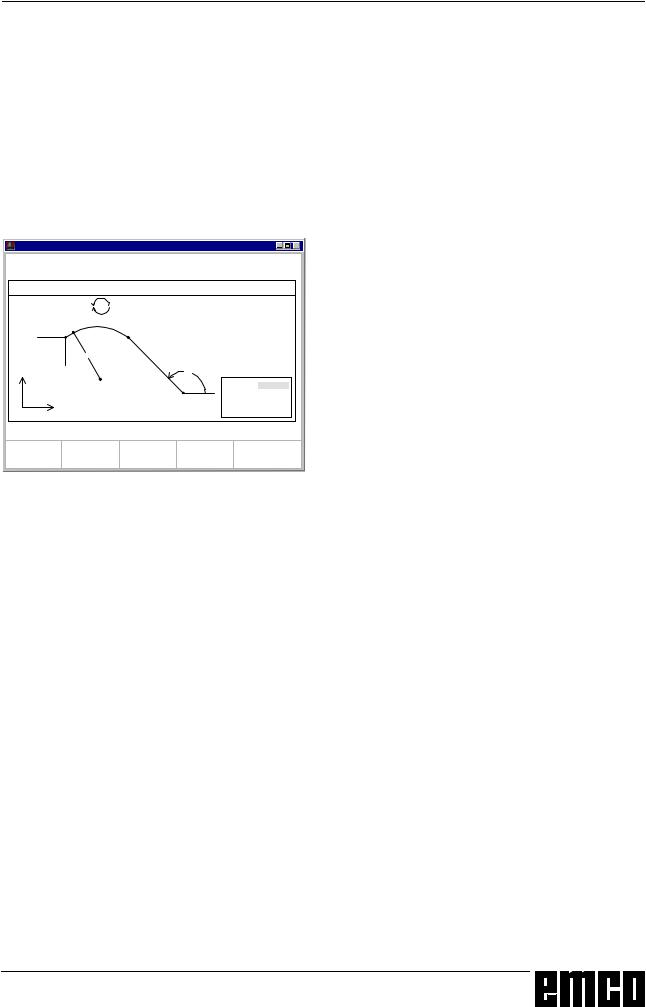
Input pattern for guiding line-circle
Program Input with Guiding Function
In an openend program you can enter blocks guided by menues.
Frequently used G and M commands are displayed as softkey functions.
It is also possible to enter predefined contour drafts without need to calculate intermediate positions.
Example: Program contour draft line - circle
•Press softkey GUIDING
•Press softkey GEOM. PATH
•Press softkey LINE - CIRCLE
•The input pattern beside will be displayed. The selected contour draft (line-circle) is displayed graphically.
•Enter with the keyboard the input values one by one.
•If in the input fields several values are in curved brackets only one of this values must be entered. If you have entered several values, you can delete the odd values with the softkey PARAM. DELETE.
•Press the softkey STORE, SOTRE MENU or STORE SELECT when input is finished.
•Now the contour draft will be stored as block in the program with all the entered geometry values. The software automatically creates a block end (LF) and displays the inserted block.
Program Input with CAD/CAM Systems
Principially NC programs can be read in from CAD/ CAM systems into WinNC SINUMERIK 810/820 M.
Act as following:
•The NC program has to be created in the format of the SINUMERIK 810/820.
•The file has to be renamed.
The NC programs of the Control System are stored as following:
%MPFxxxx ...... main program %SPFxxxx ...... subprogram (xxxx ............... program number)
E.g.: Rename with WINDOWS File Manager: From: PART1.81M
To: %MPF123
•Import the program with DATA IMPORT (see Data Input/Output).
C 4

EMCO WINNC SINUMERIK 810/820 M |
OPERATING SEQUENCES |
WinNC Sinumerik M (c) EMCO |
|
|
x |
AUTOMATIC
DATA INPUT
Available memory: 62589 Zeichen
Data type: |
|
Interface no. for data in: |
2 |
Interface allocation: |
1 = RTS-LINE |
|
2 = RTS-LINE |
DATA-IN F3 |
DATA- |
F4 |
BTR |
F5 |
DATA F6 |
STOP F7 |
START |
OUT |
|
START |
|
IMPORT |
|
|
|
|
|
|
|
|
Input pattern for data input-output
Program Administration
•Press softkey PART PROGRAM
•Press softkey PROGR.- HANDLE
•In the softkey line the functions COPY
RENAME DELETE
will be displayed
Copy Program
Example:
•Enter with keyboard %88=%5
•Press the softkey COPY
•The software copies the program %88 and stores it again with the program number %5.
The program %88 is still existing.
Rename Program
Example:
•Enter with keyboard %12=%15
•Press the softkey RENAME
•The software renames the program %12 to %15. The program %12 will not be kept.
Delete Program
Example:
•Enter with keyboard %22
•Press the softkey DELETE
•The software deletes the program %22.
Data Input-Output
•Press softkey DATA IN-OUT
•The input pattern beside will be displayed
•With "Interface no. for data in:" you can select a serial interface (1 or 2) or a drive (A, B or C).
1 serial interface COM1
2 serial interface COM2 A disk drive A
B disk drive B
C hard disk drive C, workpiece directory (can be determined with installation or with GENERAL DATA in SETTING DATA) or import/export directory (see WinConfig, 4.1 Alter Directories)
C 5

EMCO WINNC SINUMERIK 810/820 M |
OPERATING SEQUENCES |
WinNC Sinumerik M (c) EMCO |
|
|
|
|
|
|
|
x |
|
||
AUTOMATIC |
|
|
|
|
|
|
|
|
|
||
DATA IMPORT |
|
|
|
|
|
|
|
|
|
||
Main program: |
Subroutine: |
|
|
|
|
|
|
||||
Begin: % |
0 |
Begin: |
L |
0 |
|
|
|
|
|
||
End: |
% 0 |
End: |
L |
0 |
|
|
|
|
|
||
Device for data in: |
1 |
|
|
|
|
|
|
|
|
||
Device allocation: |
A= Drive A: |
|
|
|
|
|
|
||||
|
|
|
B= Drive B: |
|
|
|
|
|
|
||
|
|
|
C= Program path |
|
|||||||
|
|
|
|
|
|
|
|
||||
TOOL- |
F3 |
ZERO- F4 |
MAIN- F5 |
SUB- |
F6 |
STOP F7 |
|
||||
OFFSET |
OFFSET |
PROGRAM |
ROUTINE |
|
|
||||||
|
|
|
|
|
|
|
|
|
|
|
|
Input pattern for data import
Data Input via COM1 / COM2
•Press softkey DATA IN START. This will start the receiving function of the software.
•At the right top edge of the screen DIO (Data Input/Output) will be displayed. Destination signs the data from the sender (punched tape drive, ...).
•Start the sender.
•With the softkey STOP you can abort the data input at any time, with DATA IN START you can restart data input.
•A direct call-up of certain data by the software is not possible with data input.
Data Import
With the function data import you can load data from the drives A, B and C.
•Press softkey DATA IMPORT
•Select drive (device for data in)
•Enter below "Mainprogram" resp "Subprogram" the following program numbers:
Begin: the first program to read in End: the last program to read in
•Press the softkey MAIN PROGRAM or SUBROUTINE to start reading in the data.
•Transmission of zero offsets, tool data: Press the softkey START.
•With the softkey STOP you can interrupt the data input at any time.
C 6

EMCO WINNC SINUMERIK 810/820 M |
OPERATING SEQUENCES |
WinNC Sinumerik M (c) EMCO |
|
|
x |
AUTOMATIC
DATA OUTPUT
Available memory: 63548 Zeichen
Interface no. for data out: |
2 |
Interface allocation: |
1 = RTS-LINE |
|
2 = RTS-LINE |
|
TOOL- |
F3 |
ZERO- |
F4 |
MACH. |
F5 |
PART- |
F6 |
PLC- |
|
F7 |
|
||
|
OFFSET |
|
OFFSET |
|
DATA |
|
PROGRAM |
M-DATA |
|
|
|
|
||
Input pattern for data output |
|
|
|
|
|
|
||||||||
|
WinNC Sinumerik M (c) EMCO |
|
|
|
|
|
|
|
|
|
|
|||
|
|
|
|
|
|
|
x |
|
||||||
|
AUTOMATIC |
|
|
|
|
|
|
|
|
|
|
|
||
|
DATA OUTPUT |
|
|
|
|
|
|
|
|
|
|
|
||
|
Main program: |
|
|
|
Subroutine: |
|
|
|
|
|
||||
|
Begin: % |
0 |
|
|
Begin: |
L |
0 |
|
|
|
|
|||
|
End: |
% |
0 |
|
|
End: |
L |
0 |
|
|
|
|
||
|
Interface no. for data out: |
|
|
2 |
|
|
|
|
|
|||||
|
Interface allocation: |
|
|
|
1=RTS-LINE |
|
|
|
|
|||||
|
|
|
|
|
|
|
|
2=RTS-LINE |
|
|
|
|
||
|
|
|
|
|
|
|
|
|
||||||
|
|
F3 |
EXT |
|
F4 |
MAINPRGF5 |
SUBROUTF6 |
STOP |
|
F7 |
|
|||
|
|
|
START |
|
START |
|
START |
|
|
|
|
|
|
|
|
|
|
|
|
|
|
|
|
|
|
|
|
|
|
Input pattern for data output - part program
WinNC Sinumerik M (c) EMCO |
x |
|
AUTOMATIC |
|
|
DATA OUTPUT ZERO OFFSET/ROTATION |
||
Channel no.0 |
|
|
... |
... |
... |
Data output zero offset - rotation
WinNC Sinumerik M (c) EMCO |
|
|
x |
AUTOMATIC
DATA OUTPUT
Available memory: 36987
Interface no. for data out: |
1 |
... |
|
Input pattern for data output - printer
Data Output
•Press softkey DATA OUT.
•The screen shows the input pattern beside.
•With "Interface no. for data out" you can enter a serial interface (1 or 2) or a drive (A, B or C).
•If you send data to disks, this data will be sent in the same format as with output to the serial interface. This data have to be read in with DATA IMPORT and must not be copied directly into the workpiece directory.
Example: Program output
•Press softkey PART PROGRAM
•The screen shows the input pattern beside
•Enter below mainprogram resp. subprogram the following numbers:
Begin: the first program to be sent
End: |
the last program to be sent |
•Press softkey MAINPRG START resp. SUBRROUT START. This will start the send function of the software.
•With the softkey STOP you can interrupt data output at any time, with MAINPRG START resp. SUBROUT START you restart data output with the first program to be sent.
Example: Zero offset output
You can select to put out zero offsets or coordinate rotations.
Channel-no. 0: Output zero offsets Channel-no. 1: Output coordinate rotation
Print Data
•Press softkey DATA OUT
•The screen shows the input pattern beside.
•With "Interface no. for data out" you can enter P to select a printer.
•Act like data output
C 7

EMCO WINNC SINUMERIK 810/820 M |
OPERATING SEQUENCES |
WinNC Sinumerik M (c) EMCO |
|
|
|
|
|
|
|
x |
|
|
AUTOMATIC |
|
|
|
|
|
|
|
|
|
|
PARAMETERS OF SERIAL INTERFACES |
|
|
|
|
||||||
|
|
|
COM1 |
COM2 |
|
|
|
|
||
Baudrate |
|
9600 |
|
9600 |
|
|
|
|
|
|
Parity |
|
E |
E |
|
|
|
|
|||
Stopbits |
|
1 |
|
1 |
|
|
|
|
|
|
Databits |
|
7 |
|
7 |
|
|
|
|
|
|
Control parameter |
|
00000000 |
|
|
|
|
|
|
||
ETX-Character code |
|
00000011 |
|
|
|
|
|
|
||
|
|
|
|
|
|
|
|
|
|
|
F3 |
|
F4 |
F5 |
|
F6 |
|
|
F7 |
|
|
|
|
|
|
|
|
|
|
|
|
|
Input pattern for adjusting the serial interface
Adjusting the Serial Interface
•For transmission the interfaces of sender and receiver have to be set similar.
•Select SETTING DATA - SETTING BITS with softkeys.
Settings: |
|
Baudrate |
110, 300, 600, 1200, 2400, |
|
4800, 9600, 19200 |
Parity |
E, O, N |
Stop bits |
1, 2 |
Data bits |
7, 8 |
Data transmission from / to original control in ISOCode only.
ISO: 7 Data bits, Parity even (=E)
Control parameter:
Bit 0: 1...Transmission will be ceased only with ETX- (End of Text) Code (not with M30, M17, M2) - this enables transmitting several programs in one sequence
Bit 7: 1...Overwrite part program without message 0...Message, if a program is already existing
ETX character code:
free setable, has to be conform with the code set at the CNC
Settings at the original control 810/820 with SETTING DATA - SETTING BITS:
5010 - 5013: |
first interface |
5018 - 5021: |
second interface |
5028: |
ETX sign |
5010, 5012: 00000000 |
|
|
||
5011, 5013: 11000xxx |
|
|
||
|
|
coded baud rate: |
||
001: |
150 bd |
010: 300 bd |
011: |
600 bd |
100: |
1200 bd |
101: 2400 bd |
110: |
4800 bd |
111: |
9600 bd |
|
|
|
NOTE
When you use an interface expansion card (e.g. for COM 3 and COM 4), take care that for every interface a separate interrupt is used (e.g.: COM1 - IRQ4, COM2 - IRQ3, COM3 - IRQ11, COM4 - IRQ10).
C 8

EMCO WINNC SINUMERIK 810/820 M |
OPERATING SEQUENCES |
Program Run
Start of a Part Program
Before starting a program the control and the machine must be ready for running the program.
•Select the mode AUTOMATIC.
•Enter the desired part program number (e.g.:
%59: % |
7 9 |
. |
•Press the key  .
.
Messages while Program Run
In the first line on the screen the influences on program run will be displayed.
HALT: AUTO interrupted
The mode was changed or the key  was pressed.
HALT: Single block
In single block mode one block was worked off (finished). Go on in program with key  .
.
HALT: Pr. stop M00, M01
Programmed interruption of the program process. Continue the program with key  .
.
HALT: Read enable
Read enable is a PLC output signal. The current block is not finished (e.g. with tool change). The next program block will be worked off after finishing the current block.
HALT: Dwell time
Processing the program is interrupted for the duration of the programmed dwell time.
FST
FEED STOP. This message will be displayed, if the PLC stops the program to execute an operation (e.g. tool change).
Program Influence
By actuating the following softkeys runnig programs can be influenced.
•Press the softkey PROGRAM CONTROL in the mode AUTOMATIC or MDI-AUTOMATIC.
•The menu line shows the following softkeys:
SKIP YES-NO |
(skip block) |
DRY ON-OFF |
(dryrun) |
OPT.STOP YES-NO |
(programmed stop) |
DEC-SBL YES-NO |
(decoding single block) |
Select this functions by pressing the corresponding softkey, deselect by pressing the softkey again.
Skip block:
Blocks in the program, which are marked by a slash before the block number (/N ...), now will not be worked off while program run.
Dryrun:
For test run without workpiece this function can be activated. All blocks with programmed feed (G01, G02, G03, G33, ...) traverse with dryrun-feed instead of the programmed feed.
The dryrun feed can be set in the setting data.
Programmed stop:
When an M01 is present in the part program, the program normally is not stopped. When the softkey function is marked with YES, the program stops with M01.
Decoding single block:
This function works in a similar way like the function SINGLE BLOCK. If this function is activated by YES, after every block, which is running through decoding, the part program will be stopped.
With the key  the program can be continued.
As difference to the normal single block mode the decoding single block mode stops also with calculation blocks.
Application: testing cycles.
C 9
 Loading...