

Page 1

MANUAL
98352000 REV. B
ECN #120110 REV. B
Page 2

PRODUCT SAFETY
Important: Before installing and operating this equipment, read & study this manual thoroughly.
Proper installation is essential to safe operation. In addition, the following points should be adhered to
in order to ensure the safety of equipment and personnel:
1. All personnel who may be expected to use this equipment must be thoroughly trained in its safe
and proper use.
2. Before flowing water from this device, check that all personnel (fire service and civilian) are out of
the stream path. Also, check to make sure stream direction will not cause avoidable property
damage.
3. Become thoroughly familiar with the hydraulic characteristics of this equipment, and the pumping
system used to supply it. To produce effective fire streams, operating personnel must be properly
trained.
4. Whenever possible, this equipment should be operated from a remote location. Do not needlessly
expose personnel to dangerous fire conditions.
5. Open the water valve supplying this equipment slowly
possible water hammer occurrence.
6. After each use, and on a scheduled basis, inspect equipment per instructions in section VII.
7. Any modifications to the electrical enclosures will destroy the NEMA 4 rating and void warranty
coverage of the enclosure and all components within.
8. Do not exceed the recommended intake and discharge pressures while operating the HEROPipe™
System. The maximum discharge pressure is 80 PSI.
so that the piping fills slowly preventing
SYSTEM INFORMATION:
System SERIAL NUMBER: ______________________________
SYSTEM ACCESSORIES:
__________________________________________________________________________________________
__________________________________________________________________________________________
__________________________________________________________________________________________
__________________________________________________________________________________________
__________________________________________________________________________________________
__________________________________________________________________________________________
2
Page 3

TABLE OF CONTENTS
I. System Callout…………………………….....…4
II. System Components……………………….…..5
A. HEROPipe™ Base
B. Waterway
C. Hydraulic Stabilizers
D. Base Clamps
SIDEWINDER™
E.
F. Nozzles
G. Handheld Controller & Docking Station
H. Battery
I. Thermal Imaging Bracket
J. Storage and Transportation Cases
EXM Monitor
III. Installation Instructions……………………..…10
A. Installation Steps
IV. Operating Instructions………………..………12
A. Normal Operation
1. Handheld Controller
2. Docking Station
B. Manual Override
V. Nozzle Flow Chart………………………........13
VI. Specifications…………………..…….……….14
A. Handheld Controller
B. Monitor Controller
C. Battery
D. Base Unit
E. Waterway
VII. Maintenance……………………….…......…15
A. Preventative Maintenance
B. Understanding the Module LEDs
*PARTS DRAWING – Please visit our website at www.elkhartbrass.com for the most current parts list.
3
Page 4
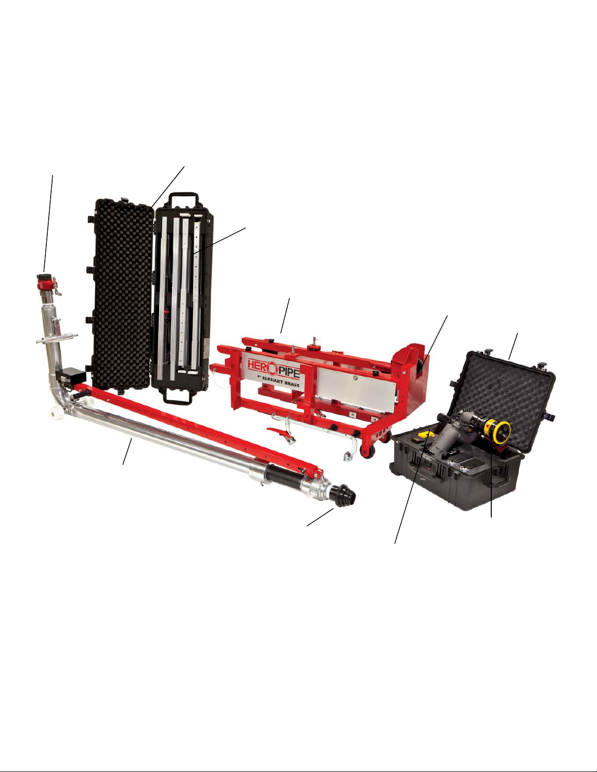
I. SYSTEM CALLOUT
X-86A Gate Valve
Stabilizer System Case
Independent Hydraulic Stabilizers
HEROPipe™ Base
Pivot Wheel
Monitor and
Accessory Case
Telescopic Aluminum Waterway
Quick Connect Coupler
for Sidewinder™ EXM
Figure 1: 8313
Handheld Controller and
Docking Station
HEROPipe™
4
Sidewinder™ EXM
Monitor
System
Page 5
II. SYSTEM COMPONENT DESCRIPTIONS
HEROPipe™
A.
Base
The HEROPipe™ base has been manufactured utilizing
lightweight, T-6061 aluminum alloy. T-6061 allows the
HEROPipe™ System to be high strength, while maintaining
lightweight advantages. The front of the base unit has been
equipped with wheels to allow users to roll it to the attack
position like a wheelbarrow.
The base unit can be secured to nearly any type of building
construction or height. The hydraulic stabilizers keep the
system securely in place whether it is on a building with a
window sill or curtain wall style construction.
B. Waterway
The waterway is manually telescopic and fabricated from
lightweight aluminum. It consists of two (2) sections; a 4”
outside diameter at the base section, and a 3 ½” outside
diameter fly section. The waterway has been designed and
tested for maximum mounting stability, force distribution, and
to ensure there are no leaks. It is retractable for maximum
mobility and can be manually extended from the base for the
greatest reach and effectiveness. The waterway is capable of
applying water from an advantageous position, the exterior of
the structure one floor below the incident, by extending to
reach the floor above.
Figure 2: 81688001
System Base
Figure 3: 81684001
System Waterway
HEROPipe™
HEROPipe™
Caution: Do not exceed the 105 PSI max intake and 80 PSI max discharge pressure during
operation.
C. Hydraulic Stabilizers
Lightweight, internally contained hydraulic load stabilizer bars.
Equipped with a large pump handle, the stabilizers are easy to
pressurize even while wearing gloves. The internal hydraulics
use a bio-safe FDA approved hydraulic fluid that is recirculated to prevent over pressurizing the system once it
reaches a 350 lb (158.7 kg) nominal end pressure. They can
effectively stabilize the HEROPipe™ system from 5 to 13.5
feet (1.5 to 4.1 meters).
An internal heavy duty coil spring keeps the stabilizer bars in
place once pressurized. Due to its retention capabilities, the
spring helps compensate the expansion and contraction of the
stabilizer bars due to temperature and/or possible flexing.
Figure 4: 81687001
System Hydraulic Stabilizers
5
HEROPipe™
Page 6
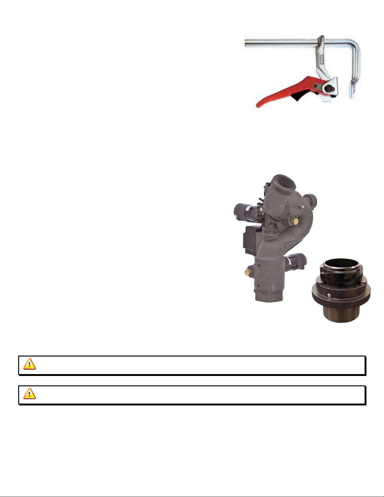
D. Base Clamps
The rapid action lever clamp is perfect for applications where
vibration causes a conventional clamp to “walk.” The lever clamp
stays firm in place even when operating at high PSI and/or GPM.
The main rail, jaw, and pressure plate are made from single cold
drawn, torsion-resistant steel that has been tempered and electrogalvanized to withstand high static stress loads, and provide
maximum tensile strength & sturdiness. The sliding clamp arm is
also made from a drop-forged, tempered, and electro-galvanized
steel to ensure perfect fit and positioning for the life of the clamp.
E.
SIDEWINDER™
EXM Monitor
The Sidewinder™ EXM monitor is specially designed for
severe duty cycles. Unique waterway swivel joints utilize
stainless steel thrust rods and needle roller thrust bearings for
unprecedented durability for fighting high-rise fires. The
monitor is controlled by an upgraded Radio Frequency (RF)
handheld controller.
The high power, permanent magnet variable speed DC gear
motors that drive the left-right and up-down movement are
NEMA 4 rated for use in harsh environments. The
Sidewinder™ EXM monitor has a flow efficient 2-1/4” vaned
waterway to minimize turbulence and provide superior nozzle
streams. The water supply connection at the monitor base is
connected to our patented quick connect coupler, and the
discharge nozzle connection has a 2-1/2” national hose male
thread.
This innovative quick connect/disconnect technology is the
perfect addition to the HEROPipe™ System and Sidewinder™
EXM unity. During a high-rise incident there are multiple
safety precautions that must be implemented. This quick
connect system was specifically engineered for the fast,
effective and reliable connection of the Sidewinder™ EXM.
Figure 5: 81683000
HEROPipe™
System Base Clamps
Figure 6: 00007113
SIDEWINDER™
EXM Monitor
Figure 7: 81691001 Quick Connect
Caution: All
SIDEWINDER™
EXM monitor motors are 12VDC.
Caution: Use only Elkhart Brass recommended nozzles.
6
Page 7

F. Nozzle
(
)
The 6000-700E is the nozzle recommended for use with the
Sidewinder™ EXM monitor. It has a range of manually
selectable flow rates and a flush setting. The nozzles provide a
constant flow in each of the flow settings. The stream pattern
adjustment is electronically actuated and controlled using the
monitor controller(s). This nozzle is rated at 80 psi nozzle
discharge pressure when operating with The HEROPipe
System.*Elkhart smooth bore nozzles may also be used.
6000-700E: 250, 350, 500, & 700 GPM
G. Handheld Controller with Docking Station
A sealed handheld remote contains all the controls necessary
for operation of the monitor, oscillation, and nozzle. The
handheld wireless remote allows the operator to control the
monitor from a significantly improved point of vantage, and
allows the team to be distanced and shielded from the extreme
conditions on the floor above. Separate push buttons are
provided for up, down, left, right, fog and straight stream, and
oscillation. The handheld remote, through the use of frequency
hopping techniques, allow multiple transmitters to operate on a
common site without interference (multiple monitors to operate
at the same incident at the same time). The remote also has an
automatic power down feature that will shut down the power
within 15 minutes of no activity, while the monitor continues
to function. As an additional power saving feature, the radio
signal is only transmitted while a button is pushed. The
handheld remote case has a NEMA 4 rating.
Figure 8:
SIDEWINDER™
EXM Nozzle
P/N: 06000701
Figure 9: 81686001 Handheld
Controller with Docking Station
Caution: Any modification to the enclosure of the handheld controller will destroy the NEMA 4
rating to that piece of equipment and will void any warranty coverage.
H. Battery
The battery pack is a 12.8V, 13.2 Ah Li-Ion rechargeable
battery. It can be charged from any DC power source 16.0V –
18.0V (>60W). It can also be charged and discharged at the
same time. The built in smart charging system provides a
constant current and constant voltage while charging or
discharging, with a MAX charge rate of 3.0A and a MAX
discharge rate of 26.0A.
The smart charger status LEDs will show the current battery
power and discharge status when the button is pressed.
Figure 10: 81675000 Battery Pack
Notice: In the event that the battery stops functioning during operation, applying the smart
charger to the battery input jack will reset the fault and re-enable it.
7
Page 8

I. Thermal Imaging Bracket
Quickly secure a thermal imaging camera to The
HEROPipe™ System by utilizing the snap-lock feature
of the Thermal Imaging Bracket. Simply lift and rotate
the clamp end of the Bracket 90° until it locks into
place. The Thermal Imaging Bracket mounts to the
discharge elbow of the Sidewinder™ EXM, which
allows thermal viewing in the direction of the stream.
Constructed from lightweight Elk-O-Lite aluminum, the
Thermal Imaging Bracket allows for rapid setup while
not weighing the system down. It stores stealthily on
the side of the monitor body when not in use. The
clamp jaw opening expands up to 1.5” when attaching a
thermal imaging camera.
8
Page 9

J. Storage and Transportation Cases
Each HEROPipe™ System will ship with two custom
Pelican™ carrying cases.
Pelican™ iM2875 Monitor System Carrying Case
Strong Polyurethane wheels with stainless steel bearings
Retractable extension handle
Easy open double throw latches
Open cell core with solid wall design
O-ring seal
Comfortable double-layered, soft-grip top and side handles
Stainless steel hardware and padlock protectors
Fitted foam with convoluted lid foam
Lifetime guarantee
Watertight, crushproof and dust proof
Int. Dimensions: 22.50 " x 21.21" x 11.40"
Weight : Approx. 40 lbs with equipment
Pelican™ 1770 Load Stabilizer System Carrying Case
Strong Polyurethane wheels with stainless steel bearings
Four extra-deep base-to-lid locking cleats
Open cell core with solid wall design
O-ring seal
Comfortable rugged double-wide side handles
Stainless steel hardware and padlock protectors
Fitted foam with convoluted lid foam
Lifetime guarantee
Watertight, crushproof and dust proof
Int. Dimensions: 54.58”x 15.58”x8.63”
Weight: Approx. 35 lbs with equipment
9
Page 10

III. INSTALLATION INSTRUCTIONS
Caution: All personnel deploying and operating this system must put on a full body harness and
attach a fall restraint lanyard to an anchor point to prevent reaching the edge. All personnel are
required to be trained and familiar with technical rescue operational guidelines.
Installation Steps:
1. Secure Base
- Roll or lift base unit into place on either a window sill or curtain wall type construction and clamp it
into place if possible.
2. Stabilize Base Unit
- Insert the lower extensions to level the system and insert push pins to secure base unit from movement.
Check clearance and slide connector boots over the top or bottom of the lower extension bars. Insert
the hydraulic stabilizers in the boot, raise them until they are as close to ceiling as possible, pin the
boot into position, and pump the hand lever to stabilize the system between the floor and ceiling. A
safety relief will activate when maximum pressure is achieved to prevent over pressurization of the
system.
Notice: Stabilizers must be within 8” from the ceiling, as they have an 8” maximum extension.
3. Adjust Length and Attach Monitor to Waterway
- Extend the waterway to the desired length prior to inserting it into the ba se unit track. Align adjustment
holes and reinsert the push pins.
- Before installing the waterway to the base unit, attach the Sidewinder™ EXM to the waterway using
the Quick Connect coupler. Be sure to connect the monitor power cable after attaching the
monitor.
4. Install Waterway
- When installing the waterway, insert the waterway into the track and roll it forward un til the first set of
black safety locks fall into place. This will keep the waterway from rolling back out of the base unit.
Caution: To limit heat exposure to the Sidewinder™ EXM, it is recommended that the hose
should be charged to the gate valve near the HEROPipe™ before rotating the waterway up into
position. An uncharged hose line should also be attached to the discharge side of the gate valve for a
quick hose connection to the HEROPipe™ intake. This will expedite water flow through the system
and minimize heat exposure.
10
Page 11

5. Connect Hose and Rotate into Position
- With a strong forward momentum, manually drive the waterway forward using the pivot wheel until
resistance is felt, then pull down on the intake section to rotate it up into position until the second set
of black safety locks fall into place. Waterway MUST stay in direct contact with pivot wheel while
raising or lowering the waterway position.
- Insert the t-bar support into the locking channels on both sides, and then rotate-n-snap the lock-pins
down into place, securing the t-bar support into position.
6. Initiate Attack
- Start water flow by opening gate valve to begin fighting fire. This should be done as quickly as
possible to protect monitor.
11
Page 12

IV. OPERATING INSTRUCTIONS
A. Normal Operation
1. Handheld Controller
Power On/Off – Press and hold the AUX button to wake up or power down the Handheld Controller.
Sleep Mode – The Handheld Controller will enter sleep mode after five minutes of inactivity. The
blue power LED will blink once every five seconds while in sleep mode. Pressing any button will
exit sleep mode and return the controller to normal operation.
Hibernate Mode – Within 10 minutes of inactivity in sleep mode, the handheld will then enter
hibernate mode. The handheld is inoperable and all LEDs will be turned off when in hibernate
mode. Pressing the AUX button will exit hibernate mode and return the controller to normal
operation.
Directional buttons – Right, Left, Up, Down, Fog, and Straight Stream – Move the monitor and nozzle
in the appropriate direction. The amber ‘Fog-Stream,’ ‘Right-Left,’ and ‘Up-down’ LEDs on the
monitor control box will light up as long as the monitor is moving in the respective directions.
Oscillate button - Used to set the limits and initiate oscillation. For a two axis oscillation:
Move monitor to the upper right position of the desired oscillation range.
Press and release the OSCILLATE button.
Move monitor to the lower left position of the desired oscillation range.
Press and release the OSCILLATE button.
The monitor will immediately start oscillating in both the horizontal and vertical directions.
In order to oscillate either horizontally only or vertically only, move the monitor only on the axis
of desired movement (horizontal or vertical).
o When oscillating in one axis only, movement in the other axis is allowed without cancelling
the oscillation.
Pressing the OSCILLATE button or moving the monitor in a direction the oscillate c ommand was
programmed for will cancel the oscillation command.
If there is no monitor movement for 30 seconds while setting up the oscillation limits, the monitor
will automatically exit oscillate setup.
Stow – Press and hold OSCILLATE and FOG simultaneously for TWO (2) or more seconds, the unit
will auto-stow.
Caution: Water should NOT be flowing while stowing the monitor.
2. Docking Station
A docking station will be utilized if the handheld input controller is used. The handheld transmitter uses
one 3.7V lithium ion battery. The docking station provides a means of charging the battery. To charge
the handheld, simply place it in the docking station and slide the top portion of the docking station
downward. This will secure the handheld as well as charge the battery.
12
Page 13

Docking Station Feedback
Initial power up – When the battery charger is first powered on the green LED will illuminate for
approximately ½ second and then turn off. Then the red LED will repeat the same
on/off cycle as the green, and finally the blue LED will do the same.
Blue LED is on solid – Power is applied to the charging station and no battery is attached
Green LED is on solid – Lithium Battery is fully charged
Blinking green LED – Lithium battery is in its final charging stage (1/10 C)
Blinking red LED – Lithium Battery is accepting full charge rate.
Rapid blinking red LED – Charging station has unsuccessfully tried to charge the lithium battery
B. Manual Override
In the event of power failure, the monitor and nozzle may be actuated manually, but only while the monitor
in NOT elevated. To operate a function manually, simply apply a ¾” ratcheting type wrench (either socket
type or ratcheting box end type) to the hex fitting on the motor shaft extension.
Caution: Do not use any power tools to operate the manual override nuts. Serious damage to
the motor gear heads will result.
Caution: All
SIDEWINDER™
V. NOZZLE FLOW CHART
Smooth Bore
Pressure
1 3/8" 1 1/2" 250 350 500 700
PSI (BAR)
80 (5.51)
500 (1893) 600 (2271) 225 (852) 315 (1192) 450 (1703) 625 (2366)
Minimum 3" hose required to supply The HEROPipe™ System
EXM monitor motors are 12VDC.
Nozzles
6000 series; 700E
Settings
GPM (LPM)
Table 1: Nozzle Flow Chart
Ft (m)
Effective Reach
8ft (2.44m) ceiling ht.
140 (42.7)
13
Page 14

VI. SPECIFICATIONS ±10% (Physical/Electrical)
A. Handheld Controller
Input power Li-Ion 3.7V
Expected battery life 3.5 hours with continuous RF Transmission
Real time clock & calendar
(RTCC) battery life 2 years without continuous power and 15 years with continuous power
Electrical Load 0.5 AMPS
RF power output Meets FCC part 15 requirements for license free operation
Transmitter dimensions 7 17/32” x 3 19/32” x 2 ¼”
Transmitter weight 1.2 lbs
Operating temperature range -14oF to +150oF
Environmental Rating NEMA 4
FCC ID KQL-2510100
Charge Time Approx. 4 hours
B. Monitor Controller
Input power 12/24 VDC (11 VDC to 27 VDC)
Electrical Load See Table 1 Below
RF power output Meets FCC part 15 requirements for license free operation
Operating temperature range -14oF to +150oF
Environmental Rating NEMA 4
FCC ID KQL-2510100
Monitor Left/Right Up/Down Nozzle
Run Current 5 A 5 A 0.5 A
Stall Current 70 A 70 A N/A
Current Trip Point 12 A 12 A 4 A
Table 2: Motor Current Specifications
C. Battery
Input power 12.8V, 13.2 Ah Li-Ion
Maximum Charge Rate 3.0A
Maximum Discharge Rate 26.0A (Can be charged and discharged at the same time)
Life Cycle 2000 Cycles
Operating Time 1.5 hours
Charge Time Approx. 6.2 hours
D. Base Unit
Dimensions (H x W x L) 30” x 22” x 60”
Weight Approx. 86 lbs
E. Waterway
Dimensions (H x W x L) 32” x 13” x 93”
Main Pipe OD 4”
Extension Pipe OD 3.5”
Intake 2.5” Female Swivel
Extension Length 7’ 9” to 15’ with monitor
Weight Approx. 81 lbs
14
Page 15

VII. MAINTENANCE
A. Preventive Maintenance (Each apparatus check or every 6 months)
1. The complete monitor and control system should be inspected during each apparatus check. Careful
inspection for damage to the monitor, and nozzle is especially important after use of the Monitor.
a. Operate all possible functions from each control point.
b. Flow water to check the nozzle pattern. If the pattern is disrupted, clear any debris.
SIDEWINDER™
EXM nozzles have a manual flush feature to clear the debris. If the obstruction
still remains, remove the nozzle and check for debris lodged between the nozzle stem and body.
c. During the nozzle flow testing, inspect monitor swivel joints for leaks.
d. Inspect all exposed wiring for signs of damage.
e. Check for proper lubrication and grease as necessary.
2. The waterway has two grease zerks that must be routinely greased. During each apparatus check or
every six months, be sure to check and grease the waterway to maintain optimal performance.
3. The pressure gauge fixed to the waterway may become less accurate over time, and should be checked
and calibrated every six (6) months or per department procedures. Remove if necessary.
Note: Although grease fittings are provided for the up/down and left/right gear cases of the monitor, routine
greasing might not be necessary. If the monitor is exposed to high level radiant heat for a prolonged period, it
may be possible for the factory grease to thin and run out of the gear cases. In such an event, fresh grease should
be applied.
It is recommended that Mobilith AW2 grease be used to lubricate the monitor gearing and waterway.
Caution: DO NOT use a high pressure spray to clean the
SIDEWINDER™
EXM or any input
controllers. Using a high pressure spray can damage seals and lead to serious damage to electrical
components.
B. Understanding the Module LEDs
1. Monitor Controller LEDs
a. When the monitor is first powered up all LEDs turn on for approximately 1 second. Then only
the power LED remains illuminated
b. When the monitor controller receives a right/left command then the horizontal LED illuminates.
c. When the monitor controller receives an up or down command then the vertical LED illuminates.
d. When the monitor controller receives a fog or stream command then the nozzle LED illuminates.
e. When in the user configuration mode, the blue status LED will illuminate
2. Input Controller LEDs
a. When the monitor is first powered up all LEDs turn on for approximately 1 second. Then only
the power LED remains illuminated
b. When any monitor/valve command button is pressed the blue power LED will flash rapidly.
c. After 5 minutes of inactivity the input controller will go to sleep. Pressing any button will exit
sleep mode and return the controller to normal operation.
d. Within 15 minutes of inactivity the input controller will hibernate. Press AUX to turn on, and
hold AUX to turn off the controller.
15
Page 16

3. Battery Smart Charger LEDs
a. Red LED = Charging (0-99%)
b. Green LED = Fully Charged (100%)
16
Page 17

ELKHART BRASS
1302 W. Beardsley Ave.
P.O. Box 1127
Elkhart, IN 46514
www.elkhartbrass.com
574 295 8330 phone
574 293 9914 fax
© 2011 Elkhart Brass Mfg. Co., Inc.
 Loading...