

Page 1
E
LLKKHHAARRTT
E
1302 WEST BEARDSLEY AVENUE • P.O. BOX 1127 • ELKHART IN 46515 • (574) 295-8330 • FAX (574) 293-9914
B
RRAASSSS
B
M
M
G
FFG
.
.
O
C
O
C
..,
,
I
I
C
NNC
..
Operating and Maintenance Instructions
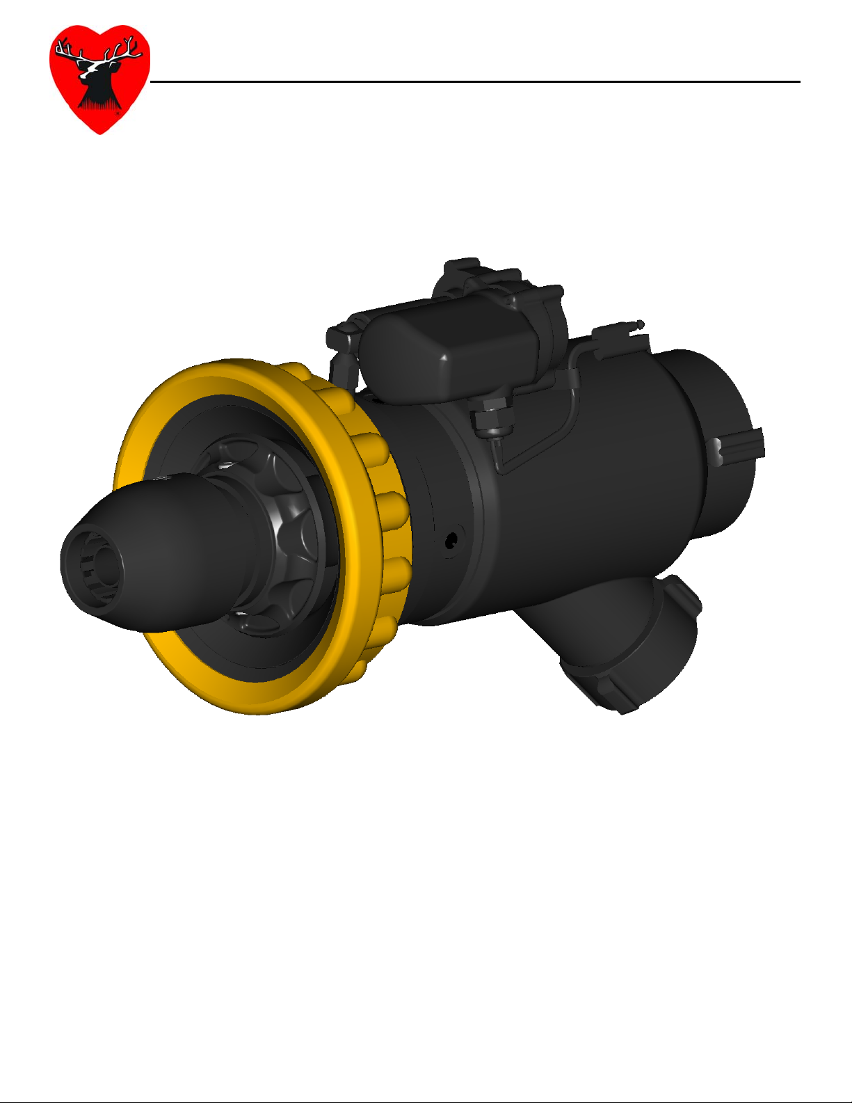
Hydro-Chem® Flex
Hydro-Chem® powder technology of Williams Fire & Hazard Control with
Flex variable smooth bore technology of Elkhart Brass.
Catalog Number: HC-750E-FLX
Part Number: 00090011
98325000 – REV. REL
Page 2

2
Page 3

Table of Contents
I. Product Safety Information......................................................................................................................... 4
II. Hydro-Chem
A. Stream Adjustment .................................................................................................................................. 5
B. Water/Foam Settings...............................................................................................................................6
C. Dry Chemical Settings............................................................................................................................. 6
III. Hydro-Chem® Flex Maintenance........................................................................................................... 7
A. Inspections................................................................................................................................................ 7
B. Maintenance After Use............................................................................................................................ 7
®
Flex Operation..................................................................................................................... 5
3
Page 4

I. PRODUCT SAFETY INFORMATION
Important:
Before installing and operating this equipment, read & study this manual thoroughly. Proper
installation is essential to safe operation. In addition, the following points should be adhered to in
order to ensure the safety of equipment and personnel:
• All personnel who may be expected to use this equipment must be thoroughly trained in its
safe and proper use.
• Before flowing this device, check that all personnel (fire service and civilian) are out of the
stream path. Also, check to make sure stream direction will not cause avoidable property
damage.
• Become thoroughly familiar with the hydraulic characteristics of this equipment, and the
pumping system used to supply it. To produce effective fire streams, operating personnel
must be properly trained.
• Open water valve supplying this equipment slowly, so that piping and hose lines fill slowly, thus
preventing possible water hammer occurrence.
• After each use, and on a scheduled basis, inspect equipment per instructions in section III.
• The maximum allowable water pressure for this nozzle is 150 psi.
• Follow dry chemical manufacturer recommendations for operations with any dry chemical
agent.
Important:
Open and close the supply valves slowly to avoid creating pressure spikes. Continually creating
pressure spikes may compromise the integrity of the nozzle. Never intentionally cause water
hammer or pressure spikes.
4
Page 5

A
II. HYDRO-CHEM
WATER/FOAM
DISCHARGE TIP
DRY CHEMICAL
DISCHARGE TIP
®
FLEX OPERATION
CTUATOR
STEM
A. Stream Adjustment
ELECTRIC;
The controls for the monitor can be used to change the nozzle’s stream pattern from straight
stream to wide fog. The 12 (24) VDC electric actuator uses a ball screw mechanism that free
spins at each end of its stroke preventing the actuator motor from experiencing a stall condition
at the ends of its stroke. The nozzle may be operated in any position from straight stream to
wide fog. Motor power required is 11-14 (22-27) VDC. Motor current draw is approximately 0.5
(0.25) Amps.
MANUAL;
The electric actuator has a ¾ inch hex nut that can be used to change the stream pattern in
the event that power is lost. Disconnecting the power lead to the nozzle will make it easier to
turn the manual override nut. NEVER
override. Using powered tools will damage the nozzle actuator and void the warranty.
use anything but a hand wrench to operate the manual
5
Page 6

B. Water/Foam Settings
The standard operating pressure for water/foam
is 75 psi at the nozzle. The Hydro-Chem® Flex
nozzle has three water/foam settings and a flush
setting. A detent has been utilized to indicate
each position. Rotating the stem clockwise from
the inlet end of the nozzle will increase the flow all the way to the flush position shown in the
picture while rotating the stem in the opposite direction will decrease the flow. The nozzle
must be shut down before changing the flow setting.
SYMBOL DESCRIPTION
FLUSH
750 GPM @ 75 PSI (2900 LPM @ 5 bar)
500 GPM @ 75 PSI (2000 LPM @ 5 bar)
300 GPM @ 75 PSI (1150 LPM @ 5 bar)
C. Dry Chemical Settings
The standard operating pressure for dry chemical/air is 150 psi at the nozzle. The discharge
size of the nozzle can be adjusted by simply rotating the dry chemical discharge tip of the
nozzle. Rotating the tip in the direction indicated by the arrows will achieve the largest
discharge setting of 20 lbs/s (9 kg/s) and the smallest discharge setting of 10 lbs/s (4.5 kg/s).
If it is desirable to have a dry chemical shut-off the nozzle, the HC-150-A shut-off is designed
to attach directly to the air inlet of the nozzle. A detent has been utilized to indicate each
discharge position. The nozzle must be shut down before changing this setting.
6
Page 7

III. HYDRO-CHEM
The following maintenance procedures should be followed in order to reduce the possibility of
field difficulty or failure.
A. Inspections
Weekly visual inspections and monthly operational checks will promote proper nozzle function.
These inspections may be done daily in busy companies. All nozzles should be flow tested
before entering any hazardous environment to ensure equipment is operating properly.
B. Maintenance After Use
The nozzle should be flushed thoroughly after every use. This can be done by flowing a clean
water source through the nozzle. The internal passageway of the nozzle should also be
visually inspected for possible damage caused by foreign objects carried by the water through
the nozzle. Periodic removal of dry chemical from the adjustable center barrel is
recommended. Follow dry chemical manufacturer recommendations for maintenance and
cleaning of the dry chemical agent portion of the nozzle.
The dry chemical discharge tip and stem portions of the nozzle rotate via a cam and slot
mechanism. If these parts become difficult to turn, remove the detent screws, coil springs and
detent balls and slide apart. Clean all parts and surfaces including the cam slots. Lubricate
the cam slot with Engineered Custom Lubricants #0025 Teflon Grease or equivalent. Use
lubricant sparingly. Excess grease will attract dirt and grit and can cause interference between
close fitting parts. Reassemble and check for proper operation.
The water/foam discharge tip is actuated electronically. If these parts become difficult to
operate, remove the two screws that retain the electric actuator and remove it. Remove the
nozzle tip and the nozzle tip o-ring. Use a mild soap & water solution to clean the outside
surface of the center barrel, the nozzle tip, and the o-ring. Inspect the o-ring and replace if
worn or damaged. Apply a thin coat of lubricant (Dow Corning #7 Lubricant/Sealant) to the oring, the outside surface of the center barrel, and the inside surface of the nozzle tip. Reinstall
the o-ring, nozzle tip, and electric actuator (see exploded drawing for Loctite requirements).
Move the nozzle tip through its entire range of motion several times to distribute the grease.
With the tip in the wide fog position, wipe off any excess grease with a clean rag. Storing the
nozzle in the wide fog position will help protect the greased surfaces from exposure to the
elements and contaminants that may be attracted by the grease.
®
FLEX MAINTENANCE
Important: If there is a question regarding any necessary repair or damage issue, contact
Elkhart Brass for assistance. Parts drawings are located on our website.
www.elkhartbrass.com
Phone #: (574)295-8330 or 800-346-0250
Email: info@elkhartbrass.com
7
Page 8

ELKHART BRASS MFG. CO., INC.
P.O. Box 1127 · 1302 West Beardsley Ave.
Elkhart, Indiana 46515
E-mail: info@elkhartbrass.com
Website: www.elkhartbrass.com
(574) 295-8330
(800) 346-0250
98325000 – REV. REL
 Loading...