

Page 1
Installation Instructions: Position Indicating Hand Wheel
GWP-4 Black (P/N 81517001)
GWP-4 Chrome (P/N 81517011)
The Indicator Hand Wheel Assembly and associated Gear Actuated Valve may be installed independently.
However, careful adherence to the following instructions is necessary to insure proper alignment of the Hand
Wheel Indicator to the Valve.
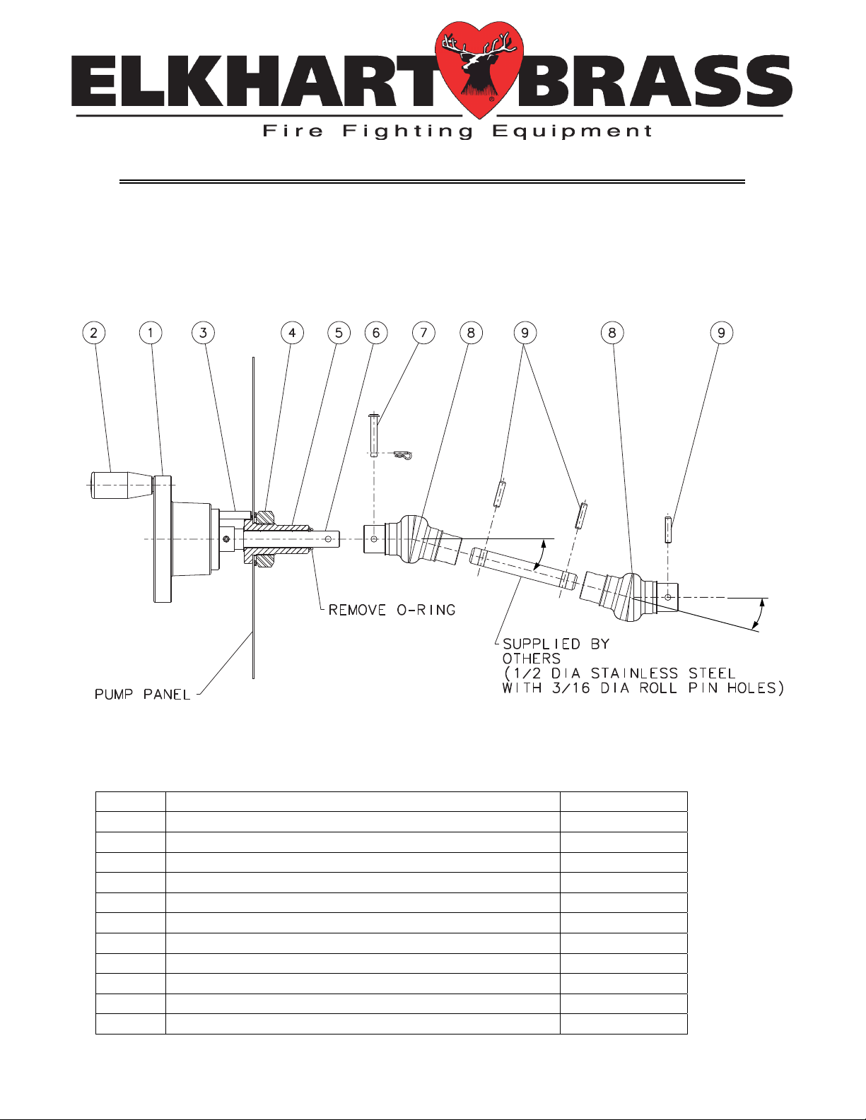
40° MAX
40° MAX
GWP-4.0
Figure 1
QTY Description ID No.
1 GWP-4 Installation Instructions N/A
1 GWP-4 Installation Template N/A
1 Indicator Hand Wheel Assembly 1
1 Hand Wheel Handle 2
1 Hand Wheel Anti-Rotation Pin 3
1 Jam Nut 4
1 Panel Adapter 5
1 Hand Wheel Shaft 6
1 Hand Wheel Clevis Pin and Clip 7
2 Universal Joint 8
3 3/16” x 0.812” Roll Pin 9
Page 1 of 3 98455000 Rev. A
Page 2

INSTALLATION OF INDICATOR HANDWHEEL ASSEMBLY
1) Identify the location of the Indicator Hand Wheel on the pump panel that will result in a 40° or less U-joint
angle (see fig. 1). The lesser the angle the smoother the operation will be. Using the installation template as a
guide (See Figure 3), drill the 1.125” diameter hole in the panel.
2) If not pre-attached, attach the Handle (ID No. 2) to the Indicator Hand Wheel Assembly. If not pre-attached,
attach the Anti-Rotation Pin (ID No. 3) to the Hand Wheel Assembly (adjustment of the pin depth will be
performed later).
3) Remove the Clevis Pin and Clip (ID No. 7) along with the Indicator Hand Wheel Assembly Nut and Locking
Washer (ID No. 4). If an o-ring has been placed over the clevis pin end of the handwheel shaft (ID No. 6) – it is
used to help hold the white plastic bushings in place during shipping and should now be removed / discarded.
4) Insert the Panel Bushing (ID No. 5) of the Indicator Hand Wheel through the panel taking care to align the
Anti-Rotation Pin to groove in the panel bushing (See Figure 2). The Anti-Rotation Pin and groove in the panel
bushing must be oriented directly above the 1.125” hole. (NOTE: exercise care not to displace the two white
plastic bushings between the Hand Wheel Shaft and Panel Bushing – one white plastic bushing is located at
each end of the Panel Bushing)
5) Secure the Panel Bushing to the panel using the Hand Wheel Assembly Nut and Locking Washer. (NOTE:
exercise care not to damage the finish of the panel bushing when holding the panel bushing to facilitate
tightening of the nut)
6) Adjust the engagement depth of the Anti-Rotation Pin and secure using the jam nut.
7) If the Indicator Hand Wheel Assembly is not immediately connected to the valve, re-install the Clevis Pin
and Clip.
Hand Wheel Anti-Rotation Pin
Figure 2
Groove in Panel Bushing
Page 2 of 3
Page 3

ALIGNMENT AND CONNECTION OF THE INDICATOR HANDWHEEL
ASSEMBLY TO THE VALVE
1) If necessary, rotate the hand wheel until the Indicator Hand Wheel pointer is aligned with the “CLOSE”
position of the indicator.
2) If necessary, manually rotate the actuator shaft of the valve until the valve is in the closed position.
Making note of the orientation of the roll pin hole on the gear actuator shaft and the indicator hand wheel shaft,
the installer is responsible to fabricate a connecting shaft of appropriate length to connect the valve to the hand
wheel assembly. The supplied universal joints (ID No. 8) and two of the supplied roll pins (ID No. 9) will be
required.
3) Attach the fabricated connecting shaft to the shaft of the gear actuator using the remaining roll pin.
4) Attach the fabricated connecting shaft to the shaft of the Indicator Hand Wheel using the Clevis Pin and Clip.
Figure 3
Installation Template
Page 3 of 3
 Loading...