

Page 1
E
LLKKHHAARRTT
E
1302 WEST BEARDSLEY AVENUE • P.O. BOX 1127 • ELKHART IN 46515 • (574) 295-8330 • FAX (574) 293-9914
B
RRAASSSS
B
M
M
G
FFG
.
.
O
C
O
C
..,
,
I
I
C
NNC
..
Operating and Maintenance Instructions
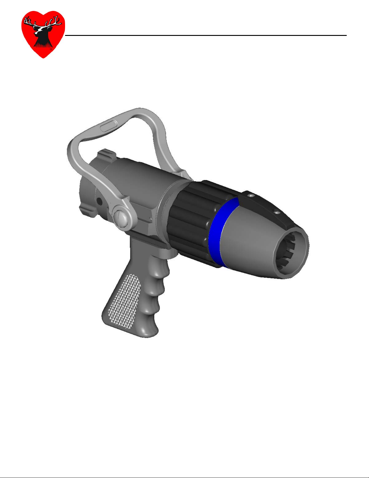
Flex Attack® – Compressed Air Foam Nozzle
Catalog Number: FLX-20G
Part Number: 00338100 REV REL
98472000 – REV. A
Page 2

Table Of Contents
I. Product Safety Information......................................................................................................................... 3
II. Product Description...................................................................................................................................... 4
A. Shutoff........................................................................................................................................................ 4
B. Pressure Balancing Mechanism............................................................................................................ 4
C. Nozzle Tip.................................................................................................................................................. 4
D. Variable Orifice Waterway...................................................................................................................... 4
III. Flex Attack
A. Discharge Adjustment ............................................................................................................................. 5
B. Discharge Settings................................................................................................................................... 5
C. Water Setting............................................................................................................................................ 5
D. Wet CAF Setting....................................................................................................................................... 6
E. Dry CAF Setting........................................................................................................................................ 6
IV. Flex Attack
A. Inspections................................................................................................................................................ 6
B. Maintenance After Use............................................................................................................................ 7
C. Storage.......................................................................................................................................................7
V. Exploded Parts Drawing…………………………………………………………………………………..8
A. Parts List………………………………………………………………………………………………….9
®
Operation............................................................................................................................ 5
®
Maintenance....................................................................................................................... 6
2
Page 3
I. PRODUCT SAFETY INFORMATION
Important:
Before installing and operating this equipment, read & study this manual thoroughly. Proper
installation is essential to safe operation. In addition, the following points should be adhered to in
order to ensure the safety of equipment and personnel:
• All personnel who may be expected to use this equipment must be thoroughly trained in its
safe and proper use.
• Before flowing water from this device, check that all personnel (fire service and civilian) are out
of the stream path. Also, check to make sure stream direction will not cause avoidable
property damage.
• Become thoroughly familiar with the hydraulic characteristics of this equipment, and the
pumping system used to supply it. To produce effective fire streams operating personnel must
be properly trained.
• Open water valve supplying this equipment slowly, so that piping and hose lines fill slowly, thus
preventing possible water hammer occurrence.
• After each use, and on a scheduled basis, inspect equipment per instructions in section VII.
• This nozzle is not designed to be used as a battering ram, sledge hammer, or forcible entry
tool.
• The maximum allowable pressure for this nozzle is 200 psi.
Important:
Open and close the valve slowly to avoid creating a water hammer. Severe water hammer may
cause the compressible bore to become inverted in the nozzle. If this occurs, simply crack the
shut-off until the compressible bore returns to proper position. Continually creating a water
hammer may compromise the integrity of the nozzle. Never intentionally cause water hammer.
3
Page 4

II. PRODUCT DESCRIPTION
The Flex Attack
in the application of Compressed Air Foam (CAF). The patented variable orifice waterway
allows the fire-fighter to adjust discharge sizes without shutting down, depending on the
requirements of the specific situation. The nozzle has been designed to flow water, wet CAF,
dry CAF, and anything in between.
A. Shutoff
The shutoff portion of the Flex Attack® nozzle features a dual drive, double seat shutoff with a
full round metal ball. The nozzle is manufactured standard with a 1.5” NH thread free swivel
inlet and an aluminum/bronze horseshoe shutoff handle. A Teflon
anodized aluminum pistol grip is also standard on the shutoff body. Special thread and handle
configurations can be addressed upon request.
B. Pressure Balancing Mechanism
This patent pending mechanism allows the nozzle to adjust between discharge orifice settings
under normal working pressures within the 40 in-lbs as required by NFPA 1964. This feature
also allows the nozzle to be fully adjusted from largest discharge orifice to the smallest in only
120 degrees of rotation. This portion of the nozzle is protected by a heavy-duty Santoprene
bumper to increase the fire-fighter’s ability to grip the nozzle.
®
Nozzle has been designed primarily to give a fire-fighter a distinct advantage
®
impregnated, hard
C. Nozzle Tip
The Flex Attack® nozzle tip is constructed from Teflon® impregnated, hard anodized aluminum.
The tip includes an indicator lug to give the fire-fighter tactile feedback on the discharge
positioning. The tip includes a set of colored labels for convenient discharge line identification.
See instructions sheet in label packet for details on label installation.
D. Variable Orifice Waterway
The patented variable orifice waterway enables the user to vary the discharge size of the
nozzle depending on the technique required to fight a fire. The variable orifice waterway
creates a fully open, unobstructed waterway in all three positions. This consists of a Zytel
ST801 adjustable center barrel and a 70A durometer compressible bore. The waterway can
be adjusted to three convenient discharge sizes.
Discharge Orifice Size
Setting Size (inches)
Water 15/16
Wet CAF 1 1/8
Dry CAF 1 3/8
®
4
Page 5

III. FLEX ATTACK
A. Discharge Adjustment
The discharge size of the nozzle can be adjusted by simply rotating the tip of the nozzle. The
adjustment of the discharge size can be accomplished without shutting the nozzle down.
Rotating the tip to the right (clockwise) will achieve the smallest discharge diameter. Rotating
the tip to the left (counterclockwise) will achieve the largest discharge diameter. A detent has
been utilized to indicate each discharge position.
B. Discharge Settings
The discharge sizes of the nozzle have been chosen to provide convenient settings for flowing
water, wet CAF, and dry CAF. The different nozzle settings only control the discharge sizes of
the nozzle. Any changes to the proportioning rates of the CAF (foam solution to air ratio) must
be adjusted at the pump panel as it would with any other nozzle. It should be noted that the
discharge setting labels are merely a recommendation. CAF can be flowed through the nozzle
in any of the three discharge settings. The flow rates of CAF through each setting will depend
on several different variables such as the water, foam, and air proportioning rates. Each
department should test the nozzle to determine which setting is suitable for each particular
application.
®
OPERATION
Important:
Each end user should become thoroughly familiar with the hydraulic characteristics of this equipment,
and the pumping system used to supply it. Personnel must be properly trained in all aspects of the
nozzle in order to produce effective fire fighting streams.
C. Water Setting
The water setting represents the smallest discharge setting of the nozzle. The discharge
diameter in this setting is 15/16”. The size of this setting was primarily chosen such that it is
possible for the user to switch from CAF to a water only stream and still maintain a usable
water stream. The size provides the user a very effective means for switching to water without
shutting down the nozzle and switching tips. The flow and reaction force characteristics of the
nozzle in this setting are comparable to a typical 15/16” smooth bore tip. The water flow rate
of the Flex Attack
rates will depend upon pump panel settings, but will exhibit the similar characteristics of a
15/16” smooth bore tip. Each department should thoroughly test the nozzle to determine the
characteristics based on their foam system.
®
in this setting is 184 GPM at 50 psi. As previously stated the CAF flow
5
Page 6

Warning:
The reaction force of this nozzle is dependent on the pressure and flow that is supplied to the nozzle.
Elevated nozzle pressure may create an unsafe reaction force for the user. The nozzle reaction
formula for water is as follows:
NR = 1.5*d2*NP
NR = Nozzle Reaction (Pounds)
D = Nozzle Diameter (Inches)
NP = Nozzle Pressure (psi)
*Formula only valid for water application.
D. Wet CAF Setting
The Wet CAF setting on the Flex Attack® has been designed to enable the user to apply a wet
solution of CAF. The discharge size of the nozzle in this setting is 1-1/8”. The CAF flow
characteristics of the nozzle in this setting will depend upon pump panel settings, but will
exhibit the similar characteristics to a 1-1/8” smooth bore tip. Each department should
thoroughly test the nozzle to determine the characteristics based on their foam system.
E. Dry CAF Setting
The Dry CAF setting on the Flex Attack® has been designed to enable the user to apply a dry
solution of CAF. This application is generally used for exposure protection. It should be noted
that a wet solution of CAF can be flowed through the nozzle in this setting. The discharge size
of the nozzle in this setting is 1-3/8”. The CAF flow characteristics of the nozzle in this setting
will depend on pump panel setting, but will exhibit similar characteristics to a 1-3/8” smooth
bore tip. Each department should thoroughly test the nozzle to determine the characteristics
based on their foam system.
IV. FLEX ATTACK
The following maintenance procedures should be followed in order to reduce to possibility of
field difficulty or failure.
A. Inspections
Weekly visual inspections and monthly operational checks will promote proper nozzle function.
These inspections may be done daily in busy companies. All nozzles should be flow tested
before entering any hazardous environment to ensure equipment is operating properly.
®
MAINTENANCE
6
Page 7

B. Maintenance After Use
The nozzle should be flushed thoroughly after every use. This can be done by flowing a clean
water source through the nozzle. The internal passageway of the nozzle should also be
visually inspected for possible damage caused by foreign objects carried by the water through
the nozzle.
C. Storage
The Flex Attack® nozzle should always be stored with ball shutoff in the open position and with
the discharge selector in the Dry CAF setting. This will ensure that no water is trapped in the
nozzle during storage.
Important:
If there is a question regarding any necessary repair or damage issue, contact Elkhart Brass for
assistance.
Phone #: 800-346-0250
Email: info@elkhartbrass.com
7
Page 8

8
Page 9

A. Flex Attack® Nozzle
(FLX-20G)
INDEX # PART # QTY DESCRIPTION
1 66424001 1 Tip - Nozzle
2 39004000 1 Indicator Lug
3 64118000 1 Cap Screw
4 64117000 1 Cap Screw
5 18114000 1 Adjustable Center Barrel
6 18461000 1 Compressible Bore
7 57542000 1 O-Ring
8 17188001 1 Body - Nozzle
9 57422000 1 O-Ring
10 44582000 1 Label - Reflective Pk
11 63699000 3 Screw - Set
12 44581000 1 Label - Discharge Identification
13 15018000 2 Ball - .187 Dia S/S
14 65703000 2 Spring - Coil
15 65067001 2 Screw - Detent
16 66425001 1 Tip - Base
17 16592000 1 Bumper Sleeve - Black
18 57482000 1 O-Ring
19 11636001 1 Adapter - Base
20 57309000 2 O-Ring
21 63863000 2 Seat - 1.375
22 57342000 2 O-Ring
23 44580000 1 Label - Open & Close
24 61269000 2 Set Screw
25 17748001 1 Body - Shut-Off
26 61286000 2 Screw - Actuator Shaft S/S
27 57298000 2 O-Ring
28 65305000 2 Shaft - Actuator D/D
29 17326001 1 1.375 Dbl Slot Valve Ball Al
30 63688000 1 Set Screw
31 11625001 1 Adapter - Base (1.5" NHT Free Sweivel)
32 16765001 1 Base - Swivel Pistol grip (1.5" NHT Free Swivel)
33 33074000 1 Gasket - Rubber (1.5" NHT Free Swivel)
34 61040000 1 Cap Screw
35 33781001 1 Pistol Grip - Elk-Olite (STD)
36A 36279000 1 Tab Handle - Chrome (STD)
36B 36684000 1 Horseshoe Handle - Chrome (STD)
37 15018000 32 Ball - .187 Dia S/S
9
Page 10

ELKHART BRASS MFG. CO., INC.
P.O. Box 1127 · 1302 West Beardsley Ave.
Elkhart, Indiana 46515
E-mail: info@elkhartbrass.com
Website: www.elkhartbrass.com
(800) 346-0250
98472000 – REV. A
 Loading...