

Page 1

UNIBODY ELECTRIC VALVE ACTUATORS E1F & E2F
GEARCASE ROTATION INSTRUCTIONS
(Please refer to Fig. 1 and 2 of this document)
1. Disconnect harness from position sensor (Item #1) if required.
2. Check that the position sensor is rotated to the maximum allowed clockwise position and that
the screw is tight to lock it in place. Re-adjust sensor if needed.
3. Remove the four cap screws and washers that retain the gearcase cover (Item #’s 2 & 3)
4. Remove the gearcase cover (Item #4). The sensor actuator shaft (Item #5) should come off
with the cover if not remove it also.
5. Make note of the position of the gear segment (Item #8) relative to the gearcase (Item #11) you
will be rotating these two items the same amount and in the same direction; when done, they
should be in the same relationship to each other as they are now. Having a sketch or digital
photo can help insure the parts get put back in the correct relationship to each other. Parts that
are put back together incorrectly can damage the position sensor (Item #1).
6. Remove the bolt and washer (Item #’s 6 & 7) that retain the gear segment (Item #8).
7. Remove the gear segment (Item #8). It may be necessary to rotate the worm (Item #9) slightly
back and forth using a wrench on the hex end of the worm gear shaft (Item #12) while
removing the gear segment.
8. Remove the four cap screws (Item #10) that secure the gearcase (Item #11) to the valve body.
9. Rotate the gearcase to its new position. It can be rotated in 45 degree increments. Make sure
the actuator shaft, the square shaft sticking up in the middle of the gearcase, does not rotate
with the gearcase. It should stay in its original position.
10.Reinstall the four cap screws (Item #10) that secure the gearcase (Item #11) to the valve body.
Apply #242 Loctite to the threads of the four screws and tighten them in an “X” pattern to 55-60
in/lbs.
11.Reinstall the gear segment (Item #8). It may be necessary to rotate the worm (Item #9) slightly
back and forth using a wrench on the hex end of the worm gear shaft (Item #12) while
reinstalling the gear segment. Be sure that the position of the gear segment (Item #8) relative
to the gearcase (Item #11) is correct. Refer to sketch or digital photo from step 4.
12.Reinstall the bolt and washer (Item #’s 6 & 7) that retain the gear segment (Item #8). Apply
#242 Loctite to the threads and tighten to 5-7 ft/lbs.
98311010 Rev-B
Page 2
13.If the sensor actuator shaft (Item #5) did not stay attached to the gearcase cover, (Item #4),
when it was removed continue with step 13; if it did stay attached, skip to step14.
14.Reinstall the sensor actuator shaft (Item #5) to the gearcase cover (Item #4) by positioning the
two parts relative to each other as shown in Fig. 2. With the sensor actuator shaft pin at the 3
o’clock position and the worm gear pocket of the gearcase cover at the12 o’clock position
press them together. The parts may stay together, if not, hold them together and go on to step
14.
15.Place the gearcase cover and sensor actuator shaft assembly down onto the gearcase so the
pin on the sensor actuator shaft (Item #5) fits into the hole on the toothed end of the gear
segment (Item #8). Carefully rotate the gearcase assembly counter-clockwise until the
mounting screw holes in the cover line up with the tapped holes in the gearcase.
16.Reinstall the four cap screws and washers that secure the gear case cover (Item #’s 2 & 3).
Apply #242 Loctite to the threads and tighten to 16 in/lbs.
17.Recalibrate the valve positions. See Valve Position Calibration on page 4 of the Quick Start
Guide on our website;
http://www.elkhartbrass.com/files/aa/downloads/manuals/98311000_Unibody_Valve_Manual.pdf
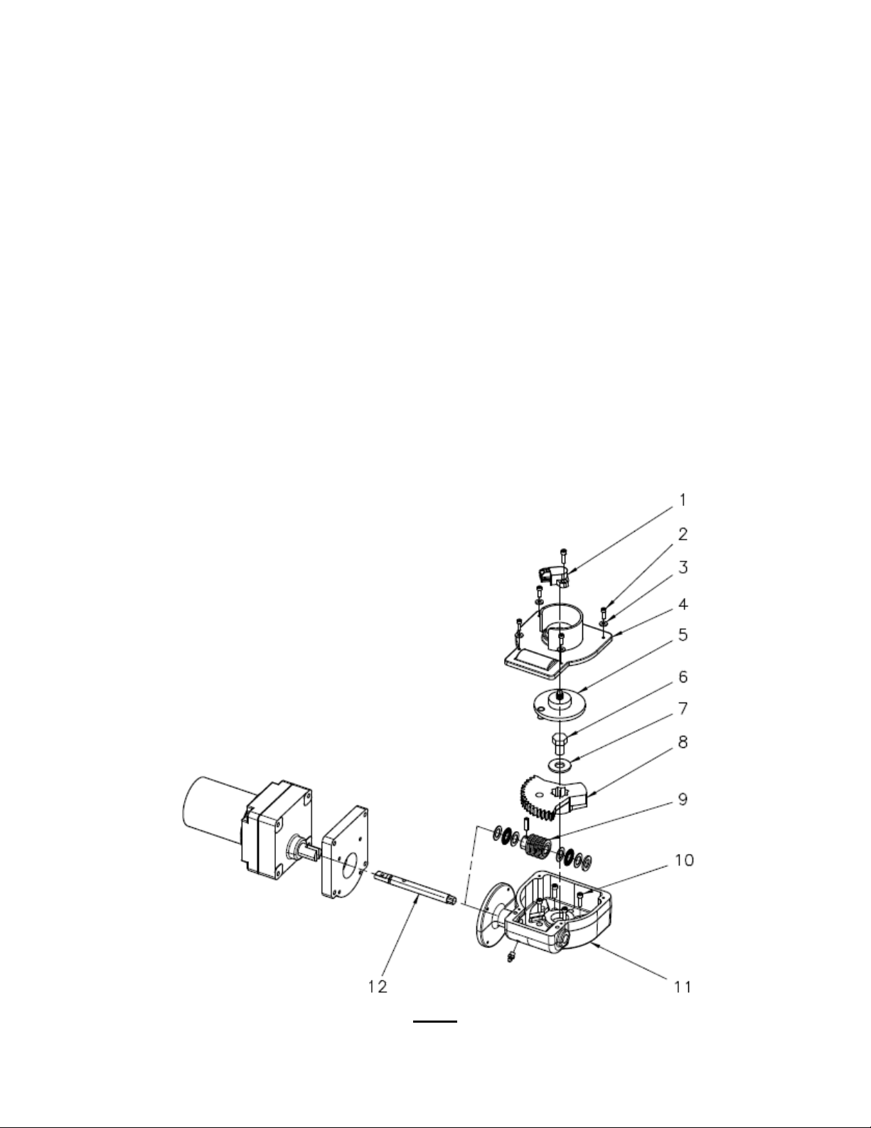
Fig. 1
(Parts are shown with valve in the OPEN position except for the EB_J valves which would be closed.)
2
Page 3

Fig. 2
3
 Loading...