

Page 1
COPPERHEAD®
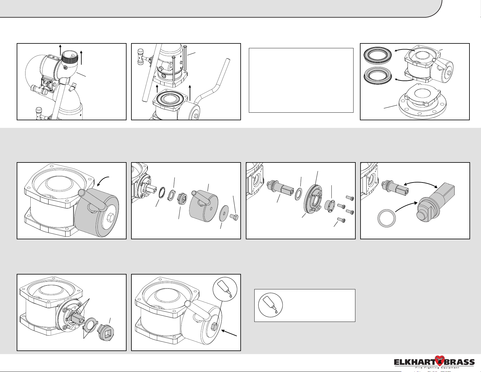
1.
A. Depressurize monitor, remove Stream
Shaper & Nozzle from Discharge Elbow,
and lock Elbow into the vertical position.
Discharge Elbow
2.
A. Before removing the hex bolt from the
end of the handle assembly, position the
valve in the closed position.
Monitor Quick Install Guide:
B. Loosen & remove the four hex bolts
and remove the upper monitor portion.
Lift monitor off slowly.
Hex Bolts
C. Remove the four cap screws followed
B. Remove the hex bolt and all the
parts in the order shown in the
illustration below.
by the bushing, valve adapter, washer,
and old actuator shaft from the valve.
Replace Blue O-Ring on Valve Adapter.
New Style Kit
NOTE: The upper portion of the
monitor and the valve assembly will
no longer be fixed to the base of the
monitor. Care should be taken
when removing these bolts.
Loosening of the lower handle and
rotation of the monitor may be
required to remove each bolt.
REMOVING UPPER MONITOR
P/N 65495001 (No Ball Included)
P/N 65496001 (Ball Included)
C. Finally, lift the valve body from the
base and remove the upper and lower
seats.
Valve Body
Base
D. Replace actuator shaft & O-ring with
the New Style Kit actuator shaft & O-ring
(A). Reinstall parts in reverse order.
1
E. Re-install the wave washer, bearing
break, and stop plate making sure the
bearing break tabs align in the slots and
the stop plate is aligned as shown below.
Valve Adapter Slots
Stop Plate
Bearing Break Tabs
Bearing Break
Handle & Cover
Hex Bolt
Wave Washer
Stop Plate
Label Washer
F. Finally, reinstall the handle & handle
cover, label washer, and hex bolt in the
orientation they were disassembled from.
Tighten bolt to 45-55 ft-lbs.
Old Actuator Shaft
Washer
Blue O-ring (F)
Bushing
Valve Adapter
Cap Screws
Indicates the use of
Loctite 242 or equivalent
Old Actuator Shaft
O-ring (A)
New Actuator Shaft
REPLACING THE ACTUATOR SHAFT
39077000 Rev. Rel
Page 2
COPPERHEAD®
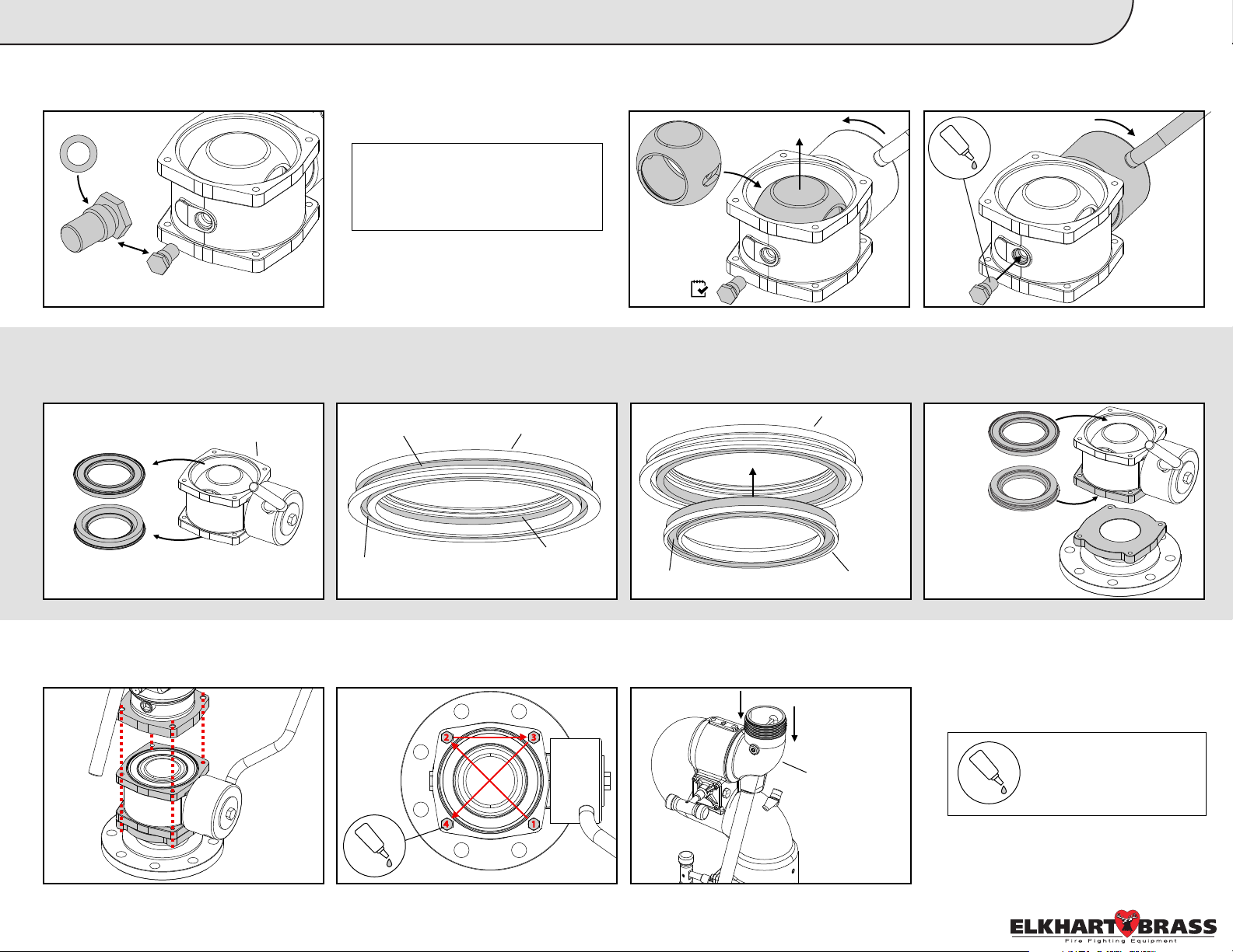
3.
A. Remove old Bolt Pivot & O-ring, and
replace with the New Style Kit Bolt Pivot
and O-ring (B).
O-ring (B)
New Bolt Pivot
Old Bolt Pivot
4.
A. Remove both the upper and lower
EB30 seats from the valve assembly if
not already done.
Monitor Quick Install Guide:
B. Confirm bolt pivot is removed, and
open the valve. Remove and replace
old ball with New Style Kit valve ball.
NOTE: For kits with a New Style
Kit Valve Ball, proceed to step B.
For kits without a new Valve Ball,
skip to step C.
BOLT PIVOT & BALL REPLACEMENT
B. To assemble lower seat, first install 2
O-rings (C) on the outside of the Brass
Retainer, and 1 O-ring (D) on the inside.
C. Next, insert the 8593 Seat into the
bottom of the brass retainer. Then place
O-ring (E) into the slot on the bottom.
New Style Kit
New Style Kit
Valve Ball
P/N 65495001 (No Ball Included)
P/N 65496001 (Ball Included)
C. Move the valve back into the closed
position before reinstalling the Bolt
Pivot. Use Loctite 242 on Bolt Pivot.
D. Make sure O-ring (E) does not fall out
of position, and construct valve assembly
onto the monitor base as shown.
2
Upper EB30 Seat
Lower EB30 Seat
5.
A. Carefully lift the monitor onto the
valve and align the bolt holes.
Valve Body
O-Ring (C)
O-Ring (C)
B. Apply Loctite to threads of all four
Hex Bolts, and tighten monitor to base
at 20 lb. increments up to 45-55 ft-lbs.
Tighten
in an X
pattern
4x
2
4
8593 Retainer
O-Ring (D)
3
1
8593 Retainer
O-Ring (E)
8593 Seat
SEAT REPLACEMENT
C. Reattach Stream Shaper and Nozzle
to discharge elbow and unlock it from
vertical position.
Discharge Elbow
New EB30 Seat
8593 Retainer
& 8593 Seat
Indicates the use of
Loctite 242 or equivalent
ATTACHING UPPER MONITOR
39077000 Rev. Rel
Page 3

COPPERHEAD®
Replacing the
Actuator Shaft
P/N 65346001 - 8593 Actuator Shaft (Qty. 1)
Bolt Pivot &
Ball
Replacement
Monitor Quick Install Guide:
P/N 57344000 - O-Ring (A) (Qty. 1)
P/N 57530000 - O-Ring (B) (Qty. 1)
New Style Kit Parts List
P/N 57290000 - Blue O-Ring (F) (Qty. 1)
P/N 65495001 (No Ball Included)
P/N 65496001 (Ball Included)
3
P/N 18473001 - 8593 Bolt Pivot (Qty. 1)
Seat
Replacement
P/N 65020000 - 8593 Seat (Qty. 1)
P/N 57442000 - O-Ring (C) (Qty. 2)
P/N 58912001 - 8593 Retainer (Qty. 1)
P/N 17331000 - EB30 Ball (Optional, Qty. 1)
P/N 65015000 - EB30 Seat (Qty. 1)
P/N 57555000 - O-Ring (E) (Qty. 1)
P/N 57378000 - O-Ring (D) (Qty. 1)
39077000 Rev. Rel
 Loading...