

Page 1
1
EXM Light Kit Install
1302 WEST BEARDSLEY AVE • ELKHART, IN 46514 • 574-295-8330 • 800-346-0250 98492000 REV REL
© 2012 ELKHART BRASS MFG. CO., INC. • WWW.ELKHARTBRASS.COM
Cobra™ EXM Light Kit Installation Instructions
Page 2
2
PREPERATION
NOTE: Before beginning installation of the light kit, turn off power to the EXM monitor.
INSTALLATION STEPS
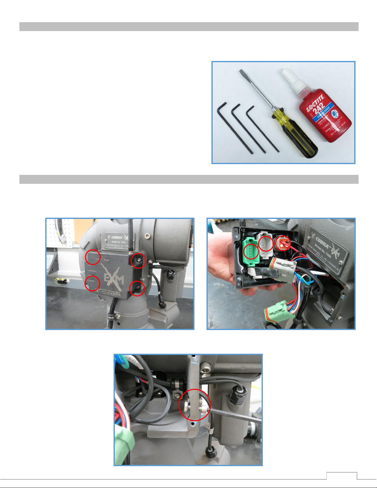
Tools needed:
You will need the following tools to install the light kit.
Allen Wrenches: 5/32”, 9/64”, 1/8”
Slotted (Flat-Head) Screwdriver
Blue Loctite #242 (or equivalent)
1. Remove the EXM control module by removing the four (4) 8-32 screws that hold it in place. Disconnect
the three (3) plugs from the control module. Store the control module and the four (4) 8-32 screws in
a place where they will not be lost or damaged; they will be used later.
2. Remove and discard the two sets of 10-24 screws and hex nuts from the side of the control module
housing.
Page 3
3
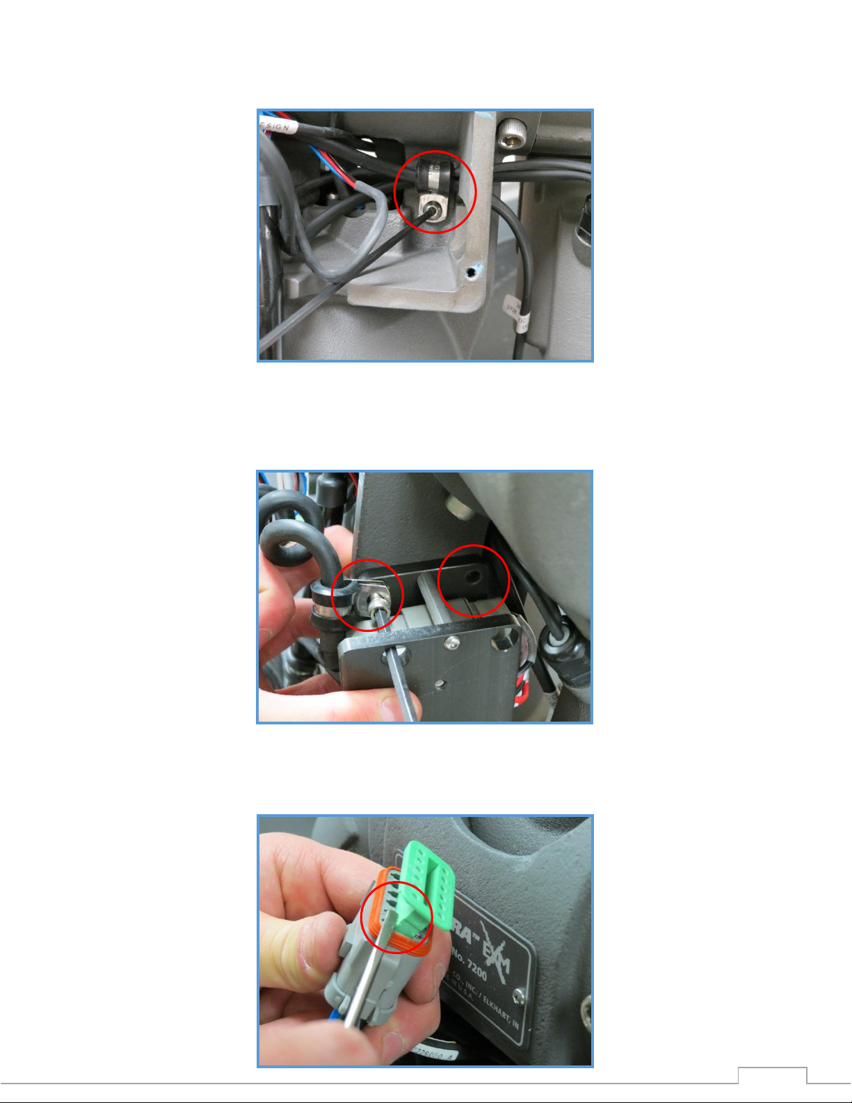
3. Remove the 10-24 button head screw and clamp loop from the inside of the control module housing.
Store the screw and clamp loop in a place where they will not be lost or damaged; they will be used
later.
4. Mount the light bracket to the now empty holes of the control module housing using the two (2) new
sets of supplied 10-24 screws and hex nuts as shown. Apply blue Loctite #242 or equivalent to the
screw threads. Use the supplied clamp loop (new with kit) to hold the harness going to the light in
place as shown.
5. Remove the wedgelock from the gray 12-pin plug on the monitor harness with a small slotted
screwdriver as shown. Store the wedgelock in a place where it will not be lost or damaged; it will be
used later.
Page 4
4
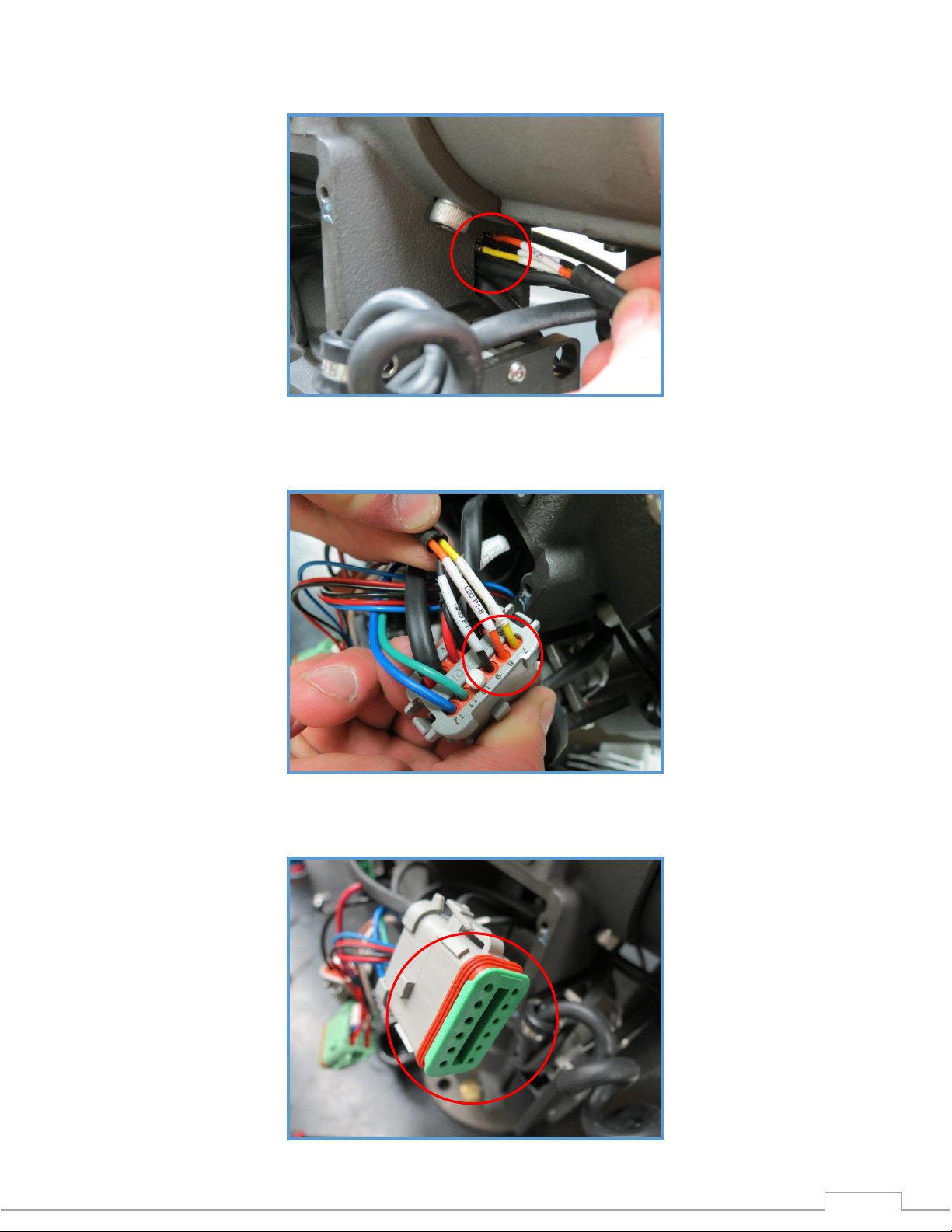
6. Insert the yellow, orange, and black wires from the light kit through the slot in the control module
housing. Pull as much of the cable through the housing as possible without putting strain on the wires.
7. Remove the white cap plugs and insert the yellow, orange, and black wires into pins 7, 8, and 9
respectively. Push the wires in until a 'click' is heard, and the wires cannot be pulled out of the plug.
8. Re-install the wedgelock previously removed into the 12-pin connector.
Page 5

5
9. Re-install the clamp loop previously removed into the back of the control module housing. Clamp
Warning: Over tightening screws may result in damage to the control module.
down all wires previously held, as well as the new yellow/orange/black cable from the light kit. Apply
blue Loctite #242 or equivalent to screw threads.
10. Plug the three (3) plugs back into the EXM control module before installing it back onto the control
module housing on the monitor. Use the four (4) 8-32 screws previously removed from the monitor.
Apply blue Loctite #242 or equivalent to the screw threads. Tighten screws to 8-10 in-lbs.
Page 6

6
11. Remove the 10-24 button head screw and clamp loop holding the monitor power harness in place.
With the supplied 10-24 round head screw, attach the supplied clamp loop and original clamp
loop as shown. Apply blue Loctite #242 or equivalent to threads.
12. If a light was received with the light kit, mount the light onto the monitor discharge elbow with the
provided ¼”-20 button head screws. Apply blue Loctite #242 or equivalent to the screw threads.
Route the light harness so that it runs in front of the light bracket as shown.
13. Power on the EXM and light kit, and test the operation of the light as outlined in the operation
instructions section below.
Page 7

7
LIGHT KIT OPERATION INSTRUCTIONS
Power must be supplied to the EXM monitor, controllers, and light kit in order to operate the light kit.
To power on a light connected to the light kit, press and hold down the AUX button and press either
FOG or STREAM. (On the joystick, roll the thumbwheel forward for STREAM and backward for FOG)
A light plugged into pins 1 and 2 will turn on when FOG is pressed
A light plugged into pins 3 and 4 will turn on when STREAM is pressed
To power off a light connected to the light kit, press and hold down the AUX button and press either
FOG or STREAM a second time. (Joystick: forward=STREAM / backward=FOG)
Page 8

ELKHART BRASS
1302 WEST BEARDSLEY AVE
P.O. BOX 1127
ELKHART, IN 46514
PHONE: 574-295-8330 • 800-346-0250
FAX: 574-293-9914
WWW.ELKHARTBRASS.COM
© ELKHART BRASS MFG. CO., INC. 2012
EXM LIGHT KIT INSTALL
COBRA™ EXM LIGHT KIT INSTALLATION INSTRUCTIONS
98492000 REV. REL
 Loading...