

Page 1
98298000 Rev. B
Page 2

Table of Contents
I. Product Safety...................................................................................................................................... 1
II. System Features.................................................................................................................................. 2
III. System Component Descriptions ...................................................................................................... 4
A. 8598 Extender ............................................................................................................................. 4
B. Controller .................................................................................................................................... 4
IV. Control System Specifications ......................................................................................................... 4
V. Mounting Structure Requirements .................................................................................................... 5
VI. Installation Instructions .................................................................................................................. 10
A. Extender ....................................................................................................................................... 10
B. Controller ..................................................................................................................................... 12
C. Wiring .......................................................................................................................................... 13
VII. Operating Instructions ................................................................................................................... 14
VIII. Maintenance and Inspection ......................................................................................................... 15
A. Extender .................................................................................................................................... 15
B. Controller Understanding the controller LED’s ........................................................................... 15
IX. Parts Drawings ................................................................................................................................ 16
X. Hydraulic Data ................................................................................................................................. 18
Page 3
I. Product Safety
Important:
Before installing and operating this equipment, read and study this manual
thoroughly. Proper installation is essential to safe operation. In addition, the
following points should be adhered to in order to ensure the safety of equipment and
personnel:
1 All personnel who may be expected to use this equipment must be thoroughly
trained in its safe and proper use.
2 Never exceed a moment of 9,480 in lbs at the outlet connection (see section V.
Mounting Structure Requirements).
3 Become thoroughly familiar with the hydraulic characteristics of this equipment
and the pumping system used to supply it. To produce effective fire streams,
operating personnel must be properly trained.
4 Whenever possible, this equipment should be operated from a remote location.
Do not needlessly expose personnel to dangerous fire conditions.
5 Open water valve supplying this equipment slowly, so that the piping fills slowly,
thus preventing possible water hammer occurrence.
6 After each use, and on a scheduled basis, inspect equipment per instructions
(see section VIII. Maintenance and Inspection)
7 Any modification to the controller’s enclosure will destroy the NEMA 4 rating and
void warranty coverage of the enclosure and all components within.
1
Page 4
II. System Features
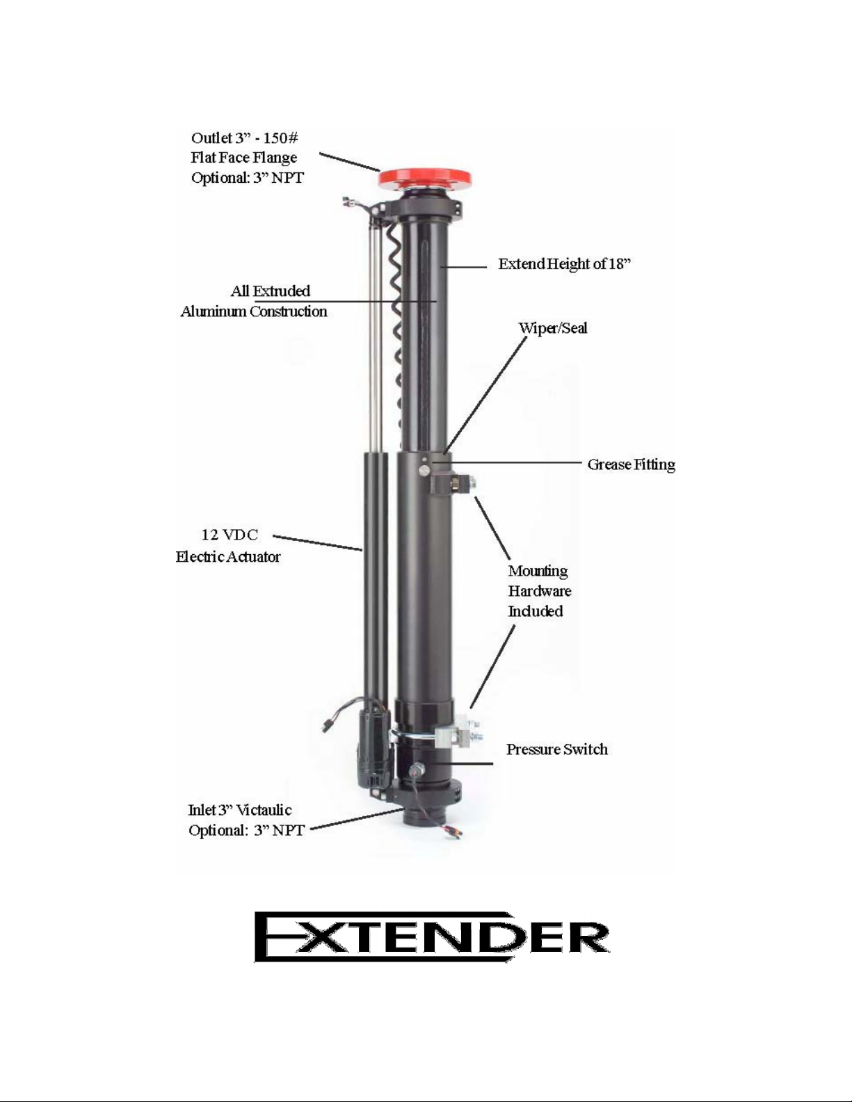
Figure 1
8598 Features
2
Page 5

Figure 2
Extender Front Panel Controller Features
3
Page 6

III. System Component Descriptions
A. 8598 Extender
The Extender is an electric operated telescoping waterway. It is designed to elevate a
deck monitor 18 inches so the stream path can clear obstructions like truck cab, lights,
hose bed, etc. It is designed to be used in full up position, but can be used in the full
down position. The water supply connection is 3 inch Victaulic (optional 3 inch NPT
male thread). The discharge connection is 3 inch 150 lb. ANSI pattern flange (optional 3
inch NPT male threads).
The maximum flow capacity is 1250 gallons per minute. The maximum inlet pressure is
200 psi. A pressure switch prevents the Extender from moving when internal pressure
exceeds 10 psi to prevent damage to equipment or injury to personnel caused by
unexpected changes in stream elevation.
B. Controller
The Extender’s control circuit uses a state-of-the-art control logic to keep the controller
size to a minimum. The controller utilizes modern switch styles to control the deck gun
elevator. A momentary push elevates or lowers the unit. The unit does not stop in mid
position. An optional in-cab warning lamp (supplied by the OEM) shows if the Extender
is not fully retracted.
IV. Control System Specifications
Truck Voltage
Minimum 11 VDC to Maximum 15 VDC
Recommended Ratings
Operating voltage - 13.8 VDC
Primary fuse rating - 10A
Position warning output fuse rating - 125mA
Extender
Maximum flow capacity is 1250 gpm
Maximum inlet pressure rating is 200 psi
Maximum moment is 9,480 in/lbs at the outlet connection
Moment = RFxH
Where RF = Reaction Force (Pounds)
H=Height of vertical discharge pivot (Inches) (See Figure 3)
4
Page 7
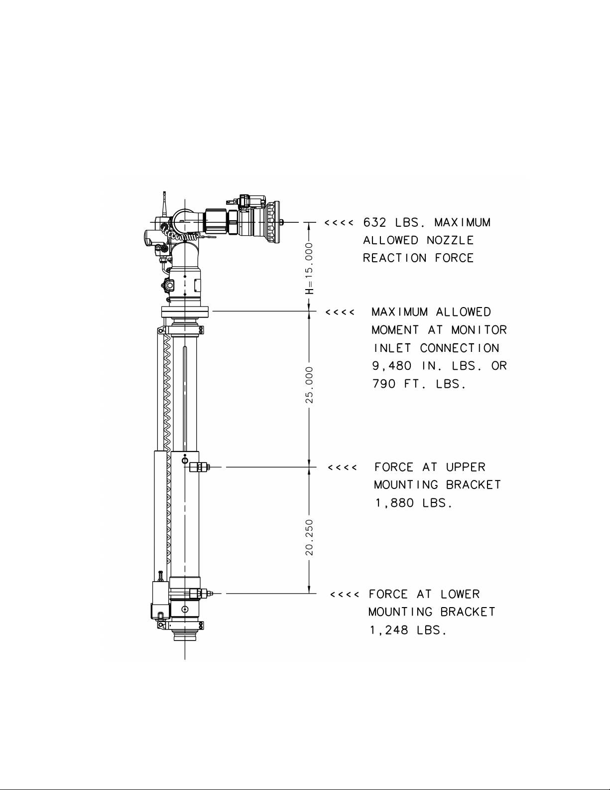
V. Mounting Structure Requirements
The mounting structure must be able to safely withstand the forces shown in Figure 3.
For monitor and nozzle combinations other than Elkhart 8500 RF and SM-1250E
consult Elkhart Brass engineering department or calculate moment at monitor inlet.
Moment must not exceed 9480 in/lb or 790 ft/lb. (See nozzle reaction formulas on page
6.)
Figure 3
Forces
5
Page 8

Equation 1
NOTES:
Nozzle Reaction Formula
STRAIGHT BORE NOZZLES
NR = 1.5 d ² NP
Where NR = Nozzle Reaction (Pounds)
d=Nozzle Diameter (Inches)
NP = Nozzle Pressure (psi)
1.5 is a constant
COMBINATION FOG NOZZLES
NR = 0.0505 Q
P
Where NR = Nozzle Reaction (Pounds) Q = Flow (GPM) P =
Nozzle Pressure (psi at base of nozzle) 0.0505 is a constant
This formula is with nozzle set on straight stream. Reaction will decrease as
pattern is widened to fog.
6
Page 9

7
Page 10

Side View Unit Dimensions
8
Page 11

Top and Bottom View Unit Dimensions
9
Page 12

VI. Installation Instructions
Warning: Mounting System not intended to support plumbing or absorb stress
from plumbing. See Figure 3.
A. Extender
1 Remove nuts (#2) and lock washers from lower mounting clamp/bracket. Loosen nuts
(#1) just enough to allow clamp/bracket to rotate on unit (for shipment, nuts (#1) were
tightened against surface “A” of the clamp body to hold the clamp in place.) See Figure 5.
2 Remove bolts, lock washers, thrust washers, and nuts from the upper
mounting bracket. See Figure 6.
Position unit onto the support structure (recommended clearance hole size for upper bolts
and lower u-bolt is 0.516-0.531 diameter) making sure the “C” surface of both the upper
mounting clamp and the lower bracket/clamp fully contact the support structure. See
Figure 4. Make sure that the clamp at the end is positioned in the retention groove of the
inlet adapter. Reinstall upper mounting bracket bolts and lower mounting bracket nuts (#2)
only enough to compress the lock washers about half way.
3 On the lower mounting bracket/clamp, position (#1) nuts loosely against surface “A” of
the mounting bracket/clamp. In small even increments, tighten (#2) nuts to 33-35 ft/lbs.
Check to see that the (#1) nuts remained loose, if either of them are tight against surface
“B” loosen them and recheck the torque on (#2) nuts.
4 Tighten lower mounting bracket (#1) nuts against surface “B” to 65-75 ft/lbs in 10 lb
increments. There is a thrust washer on the surface “B” side of (#1) nuts.
5 Tighten upper mounting bracket bolts and nuts to 65-75 ft/lbs in 10 lb increments.
6 Connect upper plug on power extension harness to plug on Elkhart “RF” monitor base.
Secure bottom end of power extension harness as required. Connect monitor power
harness 36820000 supplied with Elkhart “RF” monitor to bottom connection of power
extension harness. See monitor wiring section of Elkhart “RF” monitor instructions for
power & fusing requirements.
7 Minimize stress to mounting system by connecting inlet to water supply with flexible
hose.
10
Page 13

11
Page 14

B. Controller
1 Mark the panel cutout and mounting screw pattern per dimensions in Figure 7.
2 Cut a rectangular clearance opening and drill four 0.156 (5/32” drill) holes.
3 Insert fixed control case through panel cutout. Secure the unit to the panel with the
supplied four nuts and lock washers. Do not over tighten.
Figure 7
Extender Panel Mount Instructions
12
Page 15

C. Wiring
(See Figure 8 for connections).
Caution: Route wires away from sharp objects and heat sources.
Support with ties as needed to reduce stress on connectors and/or motor and sensor
leads.
13
Page 16

VII. Operating Instructions
NOTE: The Extender cannot be operated with water pressure above 10 PSI.
The Extender is the perfect accessory for monitors used on pumpers where the monitor
needs to clear an obstruction. The Extender is a continuous motion elevator that once
engaged will travel the full distance (18”) either up or down, without user intervention.
A. Press the “UP” button on the controller when the Extender is in the fully retracted (down)
position.
1. The unit will fully extend without the operator having to hold the button down.
2. Once the unit starts moving the yellow LED will illuminate and the green LED will
blink at a moderate rate.
3. Once the elevator is fully extended the yellow LED will extinguish and the green LED
will remain on indicating a fully extended (up) condition.
4. If, during upward travel, the operator pushes the “DOWN” button, the Extender will
immediately stop, pause for approximately one second, and start back down.
a. The yellow LED will remain on.
b. The green LED will extinguish and the red LED will start blinking once the unit
starts moving.
c. At the end of downward travel, the yellow LED will extinguish and the red LED
will remain on indicating a fully retracted (down) position.
B. Press the “DOWN” button on the controller when the Extender is in the fully extended
(up) position.
1. The unit will fully retract.
2. Once the unit starts moving, the yellow LED will illuminate and the red LED will blink
at a moderate rate.
3. Once the Extender is fully retracted, (down) the yellow LED will extinguish and the
red LED will remain on indicating a fully retracted (down) condition.
4. If, during downward travel, the operator pushes the “UP” button, the Extender will
immediately stop, pause for approximately one second, and start back up.
a. The yellow LED will remain on.
b. The red LED will extinguish and the green LED will start blinking once the unit
starts moving.
c. At the end of travel, the yellow LED will extinguish and the green LED will
remain on indicating the unit is in the fully extended (up) position.
Whenever the Extender is NOT fully retracted (down), a ground is switched on so that an
optional position warning indicator, provided by the OEM, will come on. The ground is capable
of sinking 200mA of current, which is sufficient to drive an LED or relay coil. The ground is only
available when the unit is NOT in the fully retracted position, in the fully retracted (down)
position the ground is switched off.
14
Page 17

If either button, (“UP” or “DOWN”), on the controller is pushed while the waterway is
pressurized all three LED’s will blink on and off at a very rapid rate. They will continue to blink
until the waterway pressure is less than 8 PSI and the operator pushes either the “UP” or
“DOWN” button. If the elevator is moving when the waterway becomes pressurized then the
Extender will immediately stop and all three LED’s will blink on and off at a very rapid rate.
The Extender will not move until the pressure is less than 8 PSI and the operator resets the
system by pressing either the “UP” or “DOWN” button. Pushing the “UP” or “DOWN” button will
stop the flashing LED’s reset the LED’s back to their normal mode of operation and start the
unit traveling in the chosen direction.
NOTE: Once the pressure has been released and the unit has been reset, all functions will
return to their normal mode of operation.
VIII. Maintenance and Inspection
A. Extender
The complete Extender system should be inspected during each apparatus check. Careful
inspection for damage to the Extender is especially important after use in emergency
operations.
1. Operate each function (Up-Down) with the controller.
2. Inspect all exposed wiring for signs of damage.
3. Inspect nuts and bolts for signs of damage.
4. Grease as needed to maintain a thin film of grease on the extension tube.
Grease with unit down. Wipe off excess grease and grit that accumulates at the
top of the outer tube and wiper.
B. Controller
Understanding the controller LED’s
1. Red LED on - Extender is all the way down.
2. Green LED on - Extender is all the way up.
3. Red LED flashing and yellow LED on - Extender is traveling down.
4. Green LED flashing and yellow LED on - Extender is traveling up.
5. Green, Yellow, and Red LED flashing - An error condition exists. Unit is
pressurized and one of the travel buttons was pressed or the unit was traveling
and the waterway became pressurized.
15
Page 18

IX. Parts Drawings
16
Page 19

ITEM
P/ N
DESCRIPTION
QTY
1 31030000
2 64096000
3 23576000
4 61076000
5 17841001
6 57590000
7 51135001
8 64097000
9 57314000
10 36839000
11 66675001
12 62157000
13 20432001
14 10844001
15 62158000
16 71550000
17 47489000
18 33409001
19 65555000
20 66676001
21 11521001
22 57316000
23 10498001
23 10498001
24 17857000
25 64101000
26 71543000
27 31011000
28 17835001
29 65102001
30 36838000
31 36792000
32 36793300
32 36793500
32 36793600
32 36793700
32 36793800
33 36824000
34 81385101
35 71700000
36 47498000
3"-150# COMPANION FLANGE 1
CAP SCREW 5/16-18 X 1.5 LG ZNC 4
CUSHIONED LOOP CLAMP 1
#8-32 X 0.375 BTN HD SCRW SS 1
BRACKET-ACTUATOR MOUNTING 2
RETAINING RING 3100-50-SS2 4
PIN-PIVOT 2
CAP SCREW 3/8-24 X 1.250 LG ZNC 4
ORING (568--236) 3.234 ID X 0.139 W 1
HARNESS-POWER EXTENSION 1
TUBE-EXTENSION 1
U-CUP SEAL 1
CLAMP-MOUNTING BRACKET 2
ADAPTER-OUTLET (3.0 NPTM) 1
U-CUP SEAL/WIPER 1
WASHER-SHIM (1/2 -18/8 SS) 4
HEX-NUT 1/2-13 GRADE 8 ZNC PLT 6
SCREW-STOP/GUIDE 2
STOP/GUIDE SCREW SPACER 4
TUBE-OUTER 1
ACTUATOR-18" ELECTRACK 10 1
ORING (568--242) 3.984 ID X 0.139 W 1
ADAPTER-INLET (3.0 VICT) 1
ADAPTER-INLET 3" NPTM (NOT SHOWN) 1
U BOLT 4"-W/4 NUTS ZINC PLTD 1
CAP SCREW-1/2-13 X 2.00 HEX ZNC PLT 2
WASHER-LOCK (1/2 SPLIT ZINC PLT) 4
FITTING-GREASE (3/16 DRIVE IN) 2
BRACKET-PIPE CLAMP 1
PRESSURE SENSOR W/CONN 1
HARNESS-CAUTION LAMP 1
HARNESS-POWER 1
HARNESS-( 5 FT) MOTOR/SENSOR 1
HARNESS-(10 FT) MOTOR/SENSOR 1
HARNESS-(20 FT) MOTOR/SENSOR 1
HARNESS-(30 FT) MOTOR/SENSOR 1
HARNESS-(40 FT) MOTOR/SENSOR 1
HARNESS - CONTROLLER 1
CONTROLLER W/POS INDKTR 1
#6 SPIRAL LOCK WASHER S/S 4
#6-32 HEX NUT S/S 4
17
Page 20

X. Hydraulic Data
18
Page 21

Notes:
Page 22

CORPORATE OFFICES:
ELKHART BRASS MANUFACTURING CO., INC.
1302 W. BEARDSLEY AVENUE ELKHART, IN 46514
TEL. (574) 295-8330
TOLL FREE (800) 346-0250
FAX (574) 293-9914
EMAIL: INFO@ELKHARTBRASS.COM
EXPORT OFFICE:
ELKHART BRASS INTERNATIONAL
1302 W. BEARDSLEY AVENUE ELKHART, IN 46514
TEL. (574) 295-8330
FAX (574) 295-3101
EMAIL: INFO@ELKHARTBRASS.COM
WWW.ELKHARTBRASS.COM
98298000 Rev. B
 Loading...