

Page 1

E
LLKKHHAARRTT
E
1302 WEST BEARDSLEY AVENUE • P.O. BOX 1127 • ELKHART IN 46515 • (574) 295-8330 • FAX (574) 293-9914
B
RRAASSSS
B
M
M
G
FFG
C
.. C
O
O
..,, I
I
Installation, Operating, & Maintenance Instructions
C
NNC
..
Models 8500-02, 8500-03, 8500-03X, 8593-02,
8593-03/294-11REV.06 and 8593-03X/294-11REV.06X
and
98428000 Rev. Rel
Page 2

Page 3

Table of Contents
I. PRODUCT SAFETY ..................................................................................................................1
II. INSTALLATION INSTRUCTIONS.....................................................................................2
1. 3” NPT BASE .......................................................................................................................2
2. 3” 150# FLAT FACED FLANGE ........................................................................................2
3. 4” 150# FLAT FACED FLANGE ........................................................................................2
III. OPERATING...........................................................................................................................3
1. TILLER HANDLE MONITOR 8500-02 AND 8593-02....................................................3
2. DUAL HAND WHEEL MONITOR 8500-03 AND 8593-03/294-11REV.06............3
3. DUAL HAND WHEEL FIXED BASE MONITOR 8500-03X AND 8593-03X/29411REV.06X
IV. MAINTENANCE & INSPECTION ......................................................................................3
...................................................................................................................................3
V. PARTS DRAWINGS ..................................................................................................................4
VI. MONITOR & STREAM SHAPER .....................................................................................10
1. INTERPRETING FLOW DATA .............................................................................................10
2. MONITOR AND STREAM SHAPER HYDRAULIC DATA.................................................11
Page 4
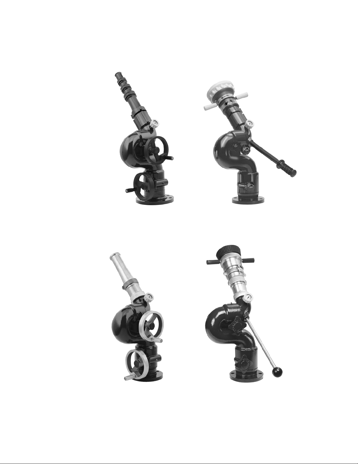
8500-03 8500-02
8500-03X
8593-03/294-11REV.06 8593-02
8593-03X/294-11REV.06X
Page 5
I. PRODUCT SAFETY
Important:
Before installing and operating this equipment, read & study this manual
thoroughly. Proper installation is essential to safe operation. In addition, the
following points should be adhered to in order to ensure the safety of equipment
and personnel:
1. All personnel who may be expected to use this equipment must be
thoroughly trained in its safe and proper use.
2. Before flowing water from this device, check that all personnel (fire
service and civilian) are out of the stream path. Also, check to make sure
stream direction will not cause avoidable property damage.
3. Become thoroughly familiar with the hydraulic characteristics of this
equipment, and the pumping system used to supply it. To produce effective
fire streams, operating personnel must be properly trained.
4. Open water valve supplying this equipment slowly
slowly, thus preventing possible water hammer occurrence.
5. After each use, and on a scheduled basis, inspect equipment per
instructions in Maintenance & Inspection on page 3.
, so that the piping fills
Warning: The piping must be able to withstand a horizontal reaction force of at least
950 lbs at the height of the discharge elbow and from any angle of rotation that the monitor is
capable of turning. Serious injury to personnel and equipment can result from improper
installation.
Page 1 98428000 Rev. Rel
Page 6

II. INSTALLATION INSTRUCTIONS
1. 3” NPT Base
Apply an appropriate thread sealant to the 3” NPT nipple. Thread the monitor base
onto the nipple. Ensure that the alignment of the fixed monitor base for the 8500-03X
and 8593-03X/294-11REV.06X is in the correct position for access to the left/right
hand wheel. Alignment for other monitors is not critical as the monitor is capable of
360º continuous rotation.
2. 3” 150# Flat Faced Flange
Attach a 3" 150 lb. class ANSI pattern companion flange to the water supply pipe.
Elkhart Brass recommends using the 81315001 Companion Flange Kit. Ensure that
the alignment of the fixed monitor base for the 8500-03X and 8593-03X/29411REV.06X is in the correct position for access to the left/right hand wheel. Attach
the monitor inlet flange to the companion flange on the water supply pipe with four (4)
5/8-11 UNC grade 5 carbon steel or stainless steel bolts, 2-1/2 inches long, with nuts.
If a wafer type butterfly valve is installed between the monitor and the companion
flange, required bolt length will be 4-1/2 inches. Seal the flange joint with a gasket, or
suitable flange sealant. Most wafer type butterfly valves have seats that serve as
flange gaskets, and separate gaskets or sealant is not required. Apply Loctite® #242
to the bolt threads, then thread on the nuts, and torque them to 60-70 ft-lbs uniformly
in increments of approximately 20ft-lbs.
3. 4” 150# Flat Faced Flange
Ensure that the alignment of the fixed monitor base for the 8500-03X and 859303X/294-11REV.06X is in the correct position for access to the left/right hand wheel.
Attach 4" 150 lb. class ANSI pattern companion flange to water supply pipe. Elkhart
Brass recommends using the 81317001 Companion Flange Kit. Attach monitor inlet
flange to companion flange on water supply pipe with eight (8) 5/8-11 UNC grade 5
carbon steel or stainless steel bolts, 2-1/2 inches long, with nuts. If a wafer type
butterfly valve is installed between the monitor and the companion flange, required
bolt length will be 4-1/2 inches. Seal flange joint with gasket, or suitable flange
sealant. Most wafer type butterfly valves have seats that serve as flange gaskets,
and separate gaskets or sealant is not required. Apply Loctite® #242 to bolt threads,
then thread on nuts, and torque to 60-70 ft-lbs uniformly in increments of
approximately 20ft-lbs.
Warning: When installing monitor on a raised face companion flange or butterfly
valve, it is critical that bolts be tightened uniformly to prevent cocking of the monitor relative to the
flange or valve. If the monitor becomes cocked, (see Figure 1) the monitor cast flange base will
fracture and fail when the bolts on the "high" side are tightened.
Figure 1
Improper Flange Installation
Page 2 98428000 Rev. Rel
Page 7

III. OPERATING
1. Tiller Handle Monitor 8500-02 and 8593-02
Turn both left/right and up/down lock handles counterclockwise to
disengage lock. Move tiller handle to desired left/right and up/down
positions. Turn both lock handles clockwise to engage lock.
2. Dual Hand Wheel Monitor 8500-03 and 8593-03/294-11REV.06
The left/right and up/down hand wheels will rotate with the monitor. Turn
the up/down hand wheel clockwise to lower nozzle or counterclockwise to
raise nozzle. Turn the left/right hand wheel clockwise to move nozzle left
or counterclockwise to move nozzle right.
3. Dual Hand Wheel Fixed Base Monitor 8500-03X and 8593-
03X/294-11REV.06X
The left/right hand wheel remains fixed while the up/down hand wheel will
rotate with the monitor. Turn the up/down hand wheel clockwise to lower
nozzle or counterclockwise to raise nozzle. Turn the left/right hand wheel
clockwise to move nozzle left or counterclockwise to move nozzle right.
IV. MAINTENANCE & INSPECTION
The monitor should be inspected regularly. Careful inspection for damage to
the monitor or nozzle is especially important after use in emergency
operations.
Flow water to check nozzle pattern. If pattern is disrupted, remove nozzle and
check for debris lodged between the nozzle stem and body, or in the stream
shaper inlet.
During nozzle flow test, inspect monitor swivel joints for leaks.
Note: Although grease fittings are provided for the up-down and left-right
gear cases, routine greasing should not be necessary. If the monitor is
exposed to a high level of radiant heat for a prolonged period, it may be
possible for the factory grease to thin and run out of the gear cases. In such
an event, fresh grease should be applied.
Page 3 98428000 Rev. Rel
Page 8

V. PARTS DRAWINGS
8500-02
July, 2005
(Vulcan)
INDEX
NO.
PART NO.
1 17906001 1 Inlet Body
2 63674000 2 Set Screw
3 31011000 2 Grease Fitting
4 63689000 2 Set Screw
5 57312000 1 O-Ring
6 15027000 92 0.250 Dia Ball S/S
7 23544000 1 Cover - Pressure Gauge
8 39130000 1 Pressure Gauge
9 28135001 1 Discharge El bow
10 80799101 2 Lock Sub-Assy
11 57316000 1 O-Ring
12 15027000 102 0.250 Dia Ball S/S
13 15616001 1 3.0"-150# Flat Face Flange
14 17952001 1 4.0"-150# Flat Face Flange
15 15620001 1 3.0-8 NPT Fem Base
16 61215100 4 Drive Screw
17 44378000 1 Label/Serial No. Tag
18 63688000 2 Set Screw
19 65363001 1 Handle Shaft
20 33645000 1 Hand Grip
QUANTITY
PER UNIT
DESCRIPTION
Page 4 98428000 Rev. Rel
Page 9

8500-03
May, 2006
(Vulcan)
INDEX NO. PART NO. DESCRIPTION QTY
1 17966001 BASE - 3" flange 1
1A 17962001 BASE - 4" Flange 1
1B 17970001 BASE - 3" NPT 1
2 63688000 SET SCREW 2
3 15027000 BALL BEARINGS 194
4 61215100 SCREW 4
5 44540000 LABEL/SERIAL TAG 1
6 31011000 GREASE FITTING 2
7 57316000 O-RING 1
8 18213001 INLET BODY 1
9 28140001 DISCHARGE ELBOW 1
10 39130000 PRESSURE GAUGE 1
11 23544000 GAUGE COVER 1
12 63674000 SET SCREW 2
13 57312000 O-RING 1
14 63795000 SET SCREW 8
15 65655001 WORM SHAFT 2
16 57380000 O-RING 2
17 71516000 THRUST WASHER 4
18 17702000 THRUST BEARING 2
19 71513000 THRUST WASHER 4
20 15699000 THRUST BEARING 2
21 57321000 O-RING 2
22 10465001 FLANGED ADAPTER 2
23 51240000 ROLL PIN 2
24 71235101 HAND WHEEL 2
25 52018000 CAP PLUG 2
26 16436001 SWIVEL BOLT 2
27 36703101 SPINNER HANDLE 2
28 16687000 SPINNER BUSHING 4
Page 5 98428000 Rev. Rel
Page 10

8500-03X
May, 2006
(Vulcan)
NO. PART NO. DESCRIPTION QTY
1 17967001 BASE - 3" flange 1
1A 17963001 BASE - 4" Flange 1
1B 17971001 BASE - 3" NPT 1
2 63688000 SET SCREW 2
3 15027000 BALL BEARINGS 194
4 61215100 SCREW 4
5 44541000 LABEL/SERIAL TAG 1
6 31011000 GREASE FITTING 2
7 57316000 O-RING 1
8 81483001 INLET BODY 1
9 28140001 DISCHARGE ELBOW 1
10 39130000 PRESSURE GAUGE 1
11 23544000 GAUGE COVER 1
12 63674000 SET SCREW 2
13 57312000 O-RING 1
14 63795000 SET SCREW 8
15 65655001 WORM SHAFT 2
16 57380000 O-RING 2
17 71516000 THRUST WASHER 4
18 17702000 THRUST BEARING 2
19 71513000 THRUST WASHER 4
20 15699000 THRUST BEARING 2
21 57321000 O-RING 2
22 10465001 FLANGED ADAPTER 2
23 51240000 ROLL PIN 2
24 71235101 HAND WHEEL 2
25 52018000 CAP PLUG 2
26 16436001 SWIVEL BOLT 2
27 36703101 SPINNER HANDLE 2
28 16687000 SPINNER BUSHING 4
Page 6 98428000 Rev. Rel
Page 11

8593-02
(Copperhead)
March, 2006
INDEX NO. PART NO. DESCRIPTI ON QTY.
1 17941001 Base-M onitor 3'-150# FF Flg 1
For Optional Base-Monitor (Brass)
Not Shown 17942001 3"-8 NPT Female THD 1
Not Shown 17944001 4.0"- 150# FF Flange Base 1
Not Shown 17943001 3"-150# FF Flange Base W/702 1
Not Shown 99402021 4"-150# FF Flange Base W/702 1
Not Shown 99401011 Pressur e Gauage Feature 1
2 15005000 Balls- 0.250 Dia. Brass 102
3 57316000 O-Ring (AS-568-242) 1
4 80296001 Handle & Knob sub-assy 1
5 31010999 Fitting-Grease (3/16 Drive-In) 1
6 61248000 .375-24 x.250 Screw-Set (B rs) 2
7 44387000 Label/Serial No. Tag 1
8 61215100 #4 x 0.187 LG. Screw drive (S/S) 4
9 63689000 8-32x. 375 Screw-Set (C up Pnt.) 2
10 61222000 .375-24 x .187 Screw-Set (Brs) 2
11 57312000 O-Ring (AS-568-237) 1
12 15005000 Balls- 0. 250 Dia. Brass 92
13 28136001 Elbow-Dischar ge (C/B) 1
14 51891000 Plug-Pipe (1/ 8 NPT) Brass 1
15 17913001 Body-Inlet (C/B) 1
16 42080001 Knob-Lock (B rass) 2
17 81329001 Lock Bushing Sub-Assy 2
18 61275000 . 25-20x.250-Screw-Set (Cup Pnt.) 2
Not Shown 23491000 Grease Fitting Cap 2
Page 7 98428000 Rev. Rel
Page 12

8593-03/294-11REV.06
(Copperhead)
May, 2006
NO. PART NO. DESCRIPTION QTY
1 17968001 BASE - 3" flange 1
1A 17964001 BASE - 4" Flange 1
1B 17972001 BASE - 3" NPT 1
2 61248000 SET SCREW 2
3 15005000 BALL BEARINGS 194
4 61215100 SCREW 4
5 44542000 LABEL/SERIAL TAG 1
6 31011000 GREASE FITTING 2
7 57316000 O-RING 1
8 18215001 INLET BODY 1
9 28141001 DISCHARGE ELBOW 1
10 51891000 PIPE - PLUG 1
11 99401011 PRESSURE GAUGE 1
12 61222000 SET SCREW 2
13 57312000 O-RING 1
14 63795000 SET SCREW 8
15 65655001 WORM SHAFT 2
16 57380000 O-RING 2
17 71516000 THRUST WASHER 4
18 17702000 THRUST BEARING 2
19 71513000 THRUST WASHER 4
20 15699000 THRUST BEARING 2
21 57321000 O-RING 2
22 10466001 FLANGED ADAPTER 2
23 51240000 ROLL PIN 2
24 71236001 HAND WHEEL 2
25 52018000 CAP PLUG 2
26 16436001 SWIVEL BOLT 2
27 36704001 SPINNER HANDLE 2
28 16687000 SPINNER BUSHING 4
Page 8 98428000 Rev. Rel
Page 13

8593-03X/294-11REV.06X
(Copperhead)
May, 2006
NO. PART NO. DESCRIPTION QTY
1 17969001 BASE - 3" flange 1
1A 17965001 BASE - 4" Flange 1
1B 17973001 BASE - 3" NPT 1
2 61248000 SET SCREW 2
3 15005000 BALL BEARINGS 194
4 61215100 SCREW 4
5 44543000 LABEL/SERIAL TAG 1
6 31011000 GREASE FITTING 2
7 57316000 O-RING 1
8 81484001 INLET BODY 1
9 28141001 DISCHARGE ELBOW 1
10 51891000 PIPE - PLUG 1
11 99401011 PRESSURE GAUGE 1
12 61222000 SET SCREW 2
13 57312000 O-RING 1
14 63795000 SET SCREW 8
15 65655001 WORM SHAFT 2
16 57380000 O-RING 2
17 71516000 THRUST WASHER 4
18 17702000 THRUST BEARING 2
19 71513000 THRUST WASHER 4
20 15699000 THRUST BEARING 2
21 57321000 O-RING 2
22 10466001 FLANGED ADAPTER 2
23 51240000 ROLL PIN 2
24 71236001 HAND WHEEL 2
25 52018000 CAP PLUG 2
26 16436001 SWIVEL BOLT 2
27 36704001 SPINNER HANDLE 2
28 16687000 SPINNER BUSHING 4
Page 9 98428000 Rev. Rel
Page 14

VI. MONITOR & STREAM SHAPER
1. Interpreting Flow Data
The following graphs offer the pressure losses for the monitor (and other devices) in terms
of Total Static Pressure Drop. This Total Static Pressure Drop can be found by measuring
the difference between the static inlet pressure and the static outlet pressure. The static
pressure at either of these points can be found using a simple pressure gauge. An
illustration of this method can be seen below.
In mathematical terms, the Total Static Pressure Drop is the change in Velocity Pressure
plus Friction Loss. The change in Velocity Pressure results from the change in velocity of
water caused by the change in the cross section of a waterway. Friction Loss results from
the drag and sidewall interference of the water through a device. A simple equation can be
seen below.
∆PS = HF + ∆P
∆PS = Total Static Pressure Drop
= Friction Loss
H
∆P
F
= Velocity Pressure Loss
V
In the firefighting industry, the terms Total Static Pressure Drop and Friction Loss tend to be
used interchangeably. However, these are significantly different measurements. This
misconception could ultimately lead to lower than anticipated performance from equipment.
When designing a system and determining performance, Total Static Pressure Drop
is the value that should always be used. The Friction Loss curve is also supplied in order
to make a comparison with competitor products that may only supply Friction Loss curves.
If there are any further questions regarding this matter, please contact Elkhart Brass.
Page 10 98428000 Rev. Rel
Page 15

2. Monitor and Stream Shaper Hydraulic Data
All Vulcan and Copperhead Monitors Listed in 98428000 Losses
50
40
30
Pressure (PSI)
20
10
0
0 200 400 600 800 1000 1200 1400
Flow Rate (GPM)
Total Static Pressure Drop Friction Loss
Friction Loss for Monitor
282-A, 282-B Stream Shaper Losses
30
25
20
15
Pressure (PSI)
10
5
0
0 200 400 600 800 1000 1200 1400
Flow Rate (GPM)
Total Static Pressure Drop
Page 11 98428000 Rev. Rel
Page 16

w
Elkhart Brass Mfg. Co., Inc.
Mailing Address:
P.O. Box 1127
Elkhart, IN 46515 USA
Shipping Address:
1302 W. Beardsley Ave.
Elkhart, IN 46514 USA
Tel. 1-574-295-8330
1-800-346-0250
Fax 1-574-293-9914
e-mail: info@elkhartbrass.com
ww.elkhartbrass.com
 Loading...