

Page 1
E
B
M
.
C
..,
I
..
E
LLKKHHAARRTT
1302 W
EST BEARDSLEY AVENUE •
B
RRAASSSS
P.O. B
OX
1127 • E
M
LKHART IN
G
.
C
FFG
46515 • (574) 295-8330 • F
O
O
,
I
NNC
AX
(574) 293-9914
C
Installation, Operating, & Maintenance Instructions
Model 8593-IV
With Integral Valve
With Integral Valve
With Integral ValveWith Integral Valve
98483000 REV. C
Page 2
I. P
Before installing and operating this equipment, read & study this manual
thoroughly. Proper installation is essential to safe operation. In addition, the
following points should be adhered to in order to ensure the safety of equipment
and personnel:
RODUCT SAFETY
Important:
1. All personnel who may be expected to use this equipment must be
thoroughly trained in its safe and proper use.
2. Before flowing water from this device, check that all personnel (fire
service and civilian) are out of the stream path. Also, check to make sure
stream direction will not cause avoidable property damage.
3. Become thoroughly familiar with the hydraulic characteristics of this
equipment, and the pumping system used to supply it. To produce effective
fire streams, operating personnel must be properly trained.
4. Open water valve slowly, so that the piping fills slowly, thus preventing
possible water hammer occurrence.
5. After each use, and on a scheduled basis, inspect equipment per
instructions in Maintenance & Inspection on page 6.
Warning: The piping must be able to withstand a horizontal reaction force of at least
950 lbs at the height of the discharge elbow and from any angle of rotation that the monitor is
capable of turning. Serious injury to personnel and equipment can result from improper installation.
Page 3

II. I
NSTALLATION INSTRUCTIONS
1. Handling
The monitor should be lifted by a strap around the monitor body casting. Lifting the
monitor by nozzle, tiller handle, valve handle, or lock handles could result in damage.
If lifting by hand, no less than two people should lift the monitor, one lifting by the
inlet flange, and the other lifting by the monitor body. The monitor with stream shaper
and nozzle weighs approximately 120 pounds so care and proper lifting techniques
should be used to avoid injury.
2. 3” 150# Flat Faced Flange
Attach a 3" 150 lb. class ANSI pattern companion flange to the water supply pipe.
Elkhart Brass recommends using the 81315001 Companion Flange Kit Attach the
monitor inlet flange to the companion flange on the water supply pipe with four (4)
5/8-11 UNC grade 5 carbon steel or stainless steel bolts, 2-1/2 inches long, with nuts.
If a wafer type butterfly valve is installed between the monitor and the companion
flange, required bolt length will be 4-1/2 inches. Seal the flange joint with a gasket,
or suitable flange sealant. Most wafer type butterfly valves have seats that serve as
flange gaskets, and separate gaskets or sealant is not required. Apply Loctite® #242
to the bolt threads, then thread on the nuts, and torque them to 60-70 ft-lbs uniformly
in increments of approximately 20ft-lbs.
3. 4” 150# Flat Faced Flange
Attach 4" 150 lb. class ANSI pattern companion flange to water supply pipe. Elkhart
Brass recommends using the 81317001 Companion Flange Kit. Attach monitor inlet
flange to companion flange on water supply pipe with eight (8) 5/8-11 UNC grade 5
carbon steel or stainless steel bolts, 2-1/2 inches long, with nuts. If a wafer type
butterfly valve is installed between the monitor and the companion flange, required
bolt length will be 4-1/2 inches. Seal flange joint with gasket, or suitable flange
sealant. Most wafer type butterfly valves have seats that serve as flange gaskets,
and separate gaskets or sealant is not required. Apply Loctite® #242 to bolt threads,
then thread on nuts, and torque to 60-70 ft-lbs uniformly in increments of
approximately 20ft-lbs.
4. 6” 150# Flat Faced Flange
Attach 6" 150 lb. class ANSI pattern companion flange to water supply pipe. Attach
monitor inlet flange to companion flange on water supply pipe with eight (8) 5/8-11
UNC grade 5 carbon steel or stainless steel bolts, 2-1/2 inches long, with nuts. If a
wafer type butterfly valve is installed between the monitor and the companion flange,
required bolt length will be 4-1/2 inches. Seal flange joint with gasket, or suitable
flange sealant. Most wafer type butterfly valves have seats that serve as flange
gaskets, and separate gaskets or sealant is not required. Apply Loctite® #242 to bolt
threads, then thread on nuts, and torque to 60-70 ft-lbs uniformly in increments of
approximately 20ft-lbs.
Page 4
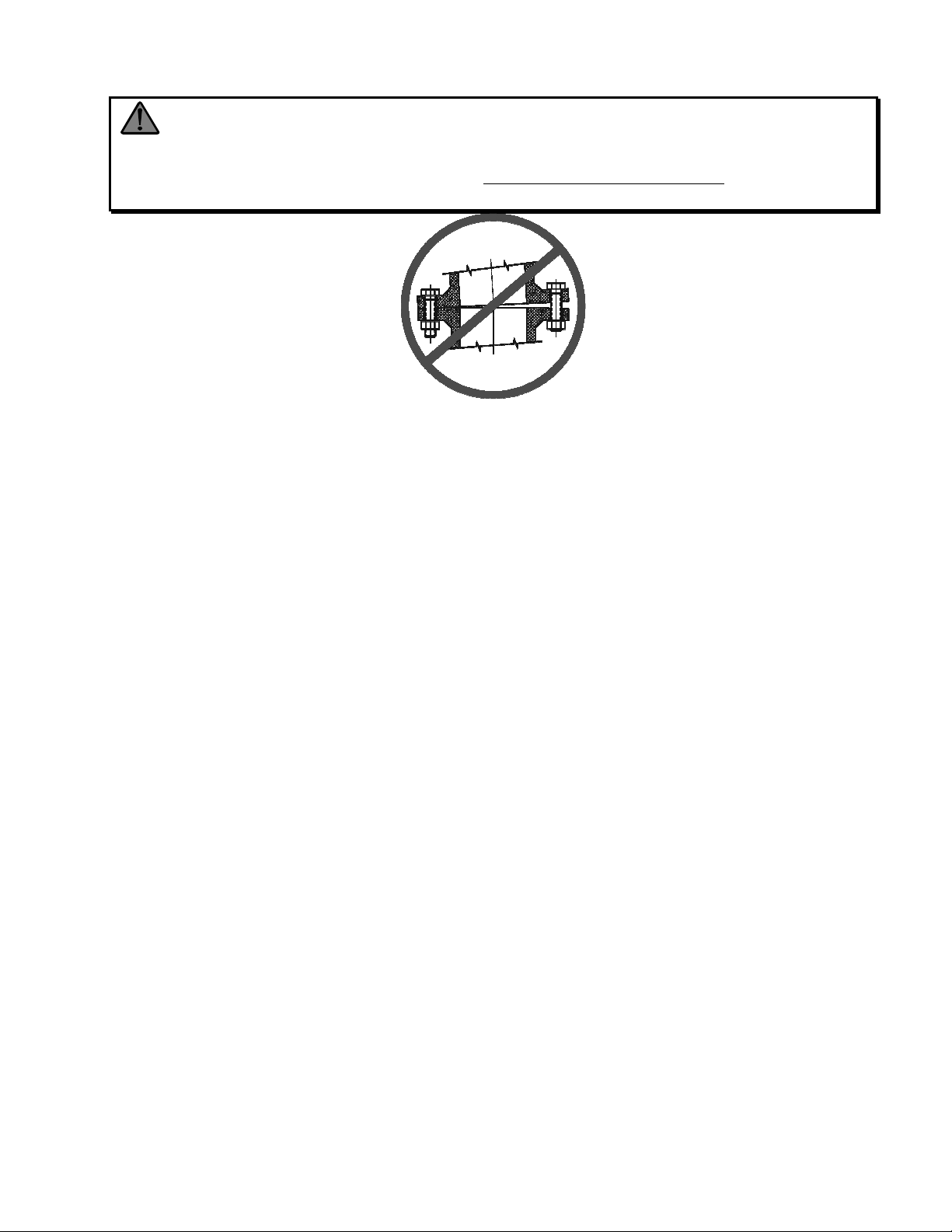
Warning: When installing monitor on a raised face companion flange, it is critical that
bolts be tightened uniformly to prevent cocking of the monitor relative to the flange. If the monitor
becomes cocked, (see Figure 1) the monitor cast flange base will fracture and fail when the bolts on
the "high" side are tightened.
Figure 1
Improper Flange Installation
Page 5
5. Valve Handle Orientation (Lever Handle)
The 8593-IV has been designed such that the valve handle may be oriented in any
one of eight possible positions that are incremented by 45 degrees. The handle may
also be oriented so that the valve opens in a clockwise or counter-clockwise rotation.
The following procedure describes proper orientation of the valve handle:
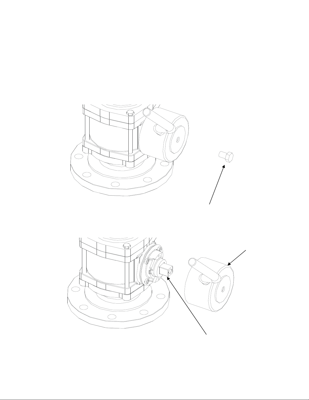
• Position the valve handle to the fully closed position
• Remove the hex bolt that attaches the valve handle (See Figure 2)
Figure 2
Hex Bolt
• Remove the handle assembly from the actuator shaft (See Figure
3)
Figure 3
Actuator Shaft
• If the direction of rotation is to be changed, remove the stop plate
from the actuator shaft, rotate 90 degrees with respect to the
Handle Assembly
Page 6
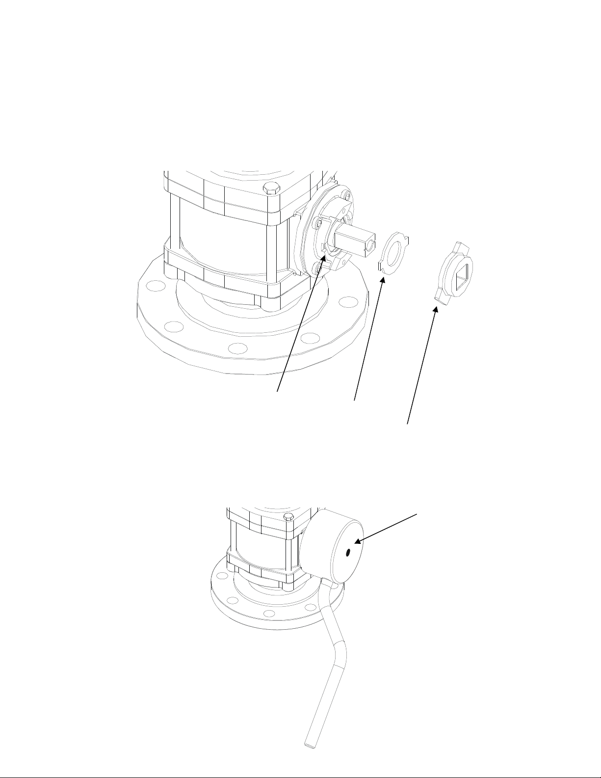
actuator shaft, then replace the stop plate on the actuator shaft.
Then rotate the actuator shaft so that the ball is in the closed
position. (See Figure 4)
• Ensure that the bearing break is lined up with the slot in the handle
adapter. If the parts are not properly aligned during installation the
handle will bind up during operation. (See Figure 4)
Figure 4
Slot
Bearing Break
Stop Plate
• Place the valve handle assembly on the actuator shaft in the
desired orientation for the closed position. (See Figure 5)
Figure 5
Handle Assembly
Page 7

• Replace the label washer and hex bolt on the handle assembly.
Apply Loctite® #242 on the hex bolt threads. Ensure that the label
washer displays the correct direction for opening the valve. (See
Figure 6)
Figure 6
Label Washer
Hex Bolt
• Tighten the hex bolt to 45ft-lbs to 55 ft-lbs
III. O
IV. M
PERATING
Monitor Tiller and Position Locks
Turn both left/right and up/down lock handles counterclockwise to disengage lock.
Move tiller handle to desired left/right and up/down positions. Turn both lock handles
clockwise to engage lock.
AINTENANCE & INSPECTION
1. Monitor Visual Inspection
The monitor should be inspected regularly. Careful inspection for damage to the
monitor or nozzle is especially important after use in emergency operations.
2. Flow Inspection
Flow water to check nozzle pattern. If pattern is disrupted, remove nozzle and check
for debris lodged between the nozzle stem and body, or in the stream shaper inlet.
During nozzle flow test, inspect monitor swivel joints for leaks.
Page 8

3. Valve Inspection/Repair
Debris in the water way could cause damage to the internal seats and or valve ball. If
leakage is detected from the internal ball valve, the seats and ball should be inspected
and replaced as needed. The following procedure describes proper inspection and
replacement of valve components:
• Remove stream shaper and nozzle from monitor discharge elbow
• Position monitor with the discharge elbow in the vertical position
and lock the vertical joint by turning the lock handle clockwise. (See
Figure 7)
• Completely loosen the four hex bolts that fasten the upper portion
of the monitor to the valve body, then carefully remove the hex bolts
(See Figure 7)
NOTE: The upper portion of the monitor will no longer be fixed
to the lower part of the monitor once the four hex bolts are
removed. Care should be taken when handling the monitor.
Hex Bolt
Figure 7
• Carefully lift the upper portion of the monitor off of the valve body,
place the upper portion of the monitor on a safe surface. (See
Figure 8)
Page 9

Valve Body
Figure 8
Upper Portion of the Monitor
• Lift the valve body off the monitor base, and remove both the EB30
seat from above the valve and the 8593 seat and brass retainer
from the bottom of the valve. Visually inspect the two seats to
determine if any damage has occurred on the sealing surfaces.
Discard the seats if damage is found.
• Remove the pivot bolt from the valve body, and place the handle in
the open position so that the valve ball may also be removed.
Visually inspect the ball to determine if any damage has occurred
such as surface scratches. Discard the ball if damage is found.
(See Figure 9)
• Place the existing or new ball in the valve body and replace the
pivot bolt. Apply Loctite® #242 to bolt threads. (See Figure 9)
Page 10

Pivot Bolt
EB30 Seat
8593 Seat
Valve Bod
y
Monitor Base
Brass Retainer
Valve Ball
Figure 9
• Place the existing or new seats in the valve body and then place
the valve body back on the monitor base. Carefully place the upper
portion of the monitor onto the valve body. (See Figure 10) NOTE:
The upper portion of the monitor will not be fixed to the lower
part of the monitor until the four hex bolts are fastened. Care
should be taken when handling the monitor.
Upper Portion of the Monitor
Figure 10
Valve Body
Monitor Base
Page 11

• Attach the four hex bolts that fasten the upper portion of the monitor
to the valve body. Apply Loctite® #242 on the hex bolt threads.
Tighten the hex bolts to 45-55 ft-lbs in uniform increments of 20 ftlbs (See Figure 11)
Hex Bolt
Figure 11
4. Valve Actuator Removal/Installation
The 8593-IV monitor is available with both lever and gear operated integral valve.
The valve actuators are interchangeable without need to break the monitor waterway.
The gear operated valve option is not currently FM approved.
The following steps outline how to remove a valve lever actuator.
• Position the valve handle to the fully closed position
• Remove the hex bolt that attaches the valve handle (See Figure 2)
• Remove the handle assembly from the actuator shaft (See Figure
3)
• Remove the 4 socket head cap screws that attach the actuator
adapter to the integral valve body (see Figure 12)
Page 12

• Remove the remaining actuator assembly from the integral valve
body (see Figure 13)
Figure 12
Socket Head Cap Screw
The following steps outline how to install a valve lever actuator.
• Install the actuator adapter sub assembly to the valve. Ensure the
valve ball is in the closed position (see Figure 13)
• Install the socket head cap screws that attach the actuator
assembly to the integral valve body use Loctite® #242 thread lock
or equivalent. (see Figure 13)
Figure 13
Page 13

• Ensure the bearing break is lined up with the slots in the handle
adapter. The handle may be installed such that the valve rotates
clockwise or counter-clockwise to open. The direction of rotation is
controlled by the installation of the stop plate. Take care to ensure
the stop plate is installed with the desired rotation. (see Figure 4)
• Install the handle assembly with the valve lever in the proper
orientation for the closed position; notice the valve lever may be
oriented in 45 degree increments. (see Figure 3)
• Install the washer and hex bolt that hold the handle assembly to the
valve actuator shaft, apply Loctite® #242 thread lock or equivalent.
(see Figure 2)
The following steps outline how to remove a valve gear actuator.
• Position the valve in the fully closed position
• Remove the socket head cap screws that attach the gear case
cover to the gear case; also remove the gear case cover. (see
Figure 14)
Gear case Cover
Socket Head
Cap Screws
Figure 14
Page 14

• Remove the socket head cap screws that attach the gear assembly
to the integral valve body. (see Figure 15)
Socket Head
Cap Screws
• Remove the gear assembly from the integral valve body. (see
Figure 16)
Figure 15
Page 15

Figure 16
The following steps outline how to install a valve gear actuator.
• Position the valve ball in the fully closed position
• Rotate the gear actuator hand wheel either fully clockwise
so that the actuator shaft will engage with the ball in the
closed position
• Install the gear actuator on the valve body in the proper
orientation (see Figure 16)
• Install the 4 socket head cap screws that attach the gear
actuator to the integral valve body (see Figure 15)
• Install the gear case cover and the four socket head cap
screws that attach the gear case cover to the gear case
(see Figure 14)
Note:
desert environment. Special fully synthetic grease is used on both vertical and horizontal
monitor swivel joints for increased longevity. No monitor components require routine
greasing.
The monitor is specially design for low maintenance and durability in the harsh
Page 16

V. F
LOW DATA
Page 17

Elkhart Brass Mfg. Co., Inc.
Mailing Address:
P.O. Box 1127
Elkhart, IN 46515 USA
Shipping Address:
1302 W. Beardsley Ave.
Elkhart, IN 46514 USA
Tel. 1-574-295-8330
1-800-346-0250
Fax 1-574-293-9914
e-mail: info@elkhartbrass.com
www.elkhartbrass.com
98483000 Rev. C
 Loading...