

Page 1

E
LLKKHHAARRTT
E
1302 WEST BEARDSLEY AVENUE • P.O. BOX 1127 • ELKHART IN 46515 • (574) 295-8330 • FAX (574) 293-9914
B
RRAASSSS
B
M
M
G
FFG
.
.
O
C
O
C
..,
,
I
I
C
NNC
..
Installation, Operating,
& Maintenance Instructions
8494
Monitor
98275000 REV. C
Page 2

Page 3

TABLE OF CONTENTS
I. PRODUCT SAFETY.....................................................................................................1
II. SYSTEM COMPONENT DESCRIPTIONS .......................................................................3
A.
B. 81206000 Control Module....................................................................................................... 3
C. 81122001 Standard Control Box ............................................................................................. 4
D. 81172001 Joystick Control Box (Optional)............................................................................. 4
E. 5000 Series Nozzles................................................................................................................. 4
F. 81181001 Water Valve Kit (Optional) ....................................................................................5
G. SM-10FE De/Anti-Icing Nozzle..............................................................................................5
III. CONTROL SYSTEM SPECIFICATIONS .........................................................................6
A. Monitor Controller Specifications........................................................................................... 6
B. Optional Valve Controller Specifications................................................................................ 6
IV. INSTALLATION INSTRUCTIONS..................................................................................7
A. Component Mounting.............................................................................................................. 7
1. Monitor......................................................................................................... 7
2. 81206000 Control Module................................................................................................... 8
3. 81122001 Control Box & 81172001 Joystick Control Box (Optional)............................... 8
4. 81181001 Water Valve Kit (Optional) ..............................................................................10
Monitor ........................................................................................................3
V. OPERATING INSTRUCTIONS.....................................................................................12
A. Normal Operation .................................................................................................................. 12
1. 81122001 Standard Control Box ....................................................................................... 12
2. 81172001 Joystick Control Box ........................................................................................ 12
B. Manual Override .................................................................................................................... 12
VI. MAINTENANCE .......................................................................................................13
A. Preventive Maintenance.........................................................................................................13
VII. MONITOR & NOZZLE HYDRAULIC DATA................................................................14
VIII. PARTS DRAWINGS...............................................................................................17
Page 4

Page 5

I. PRODUCT SAFETY
Important:
Before installing and operating this equipment, read & study this manual thoroughly.
Proper installation is essential to safe operation. In addition, the following points
should be adhered to in order to ensure the safety of equipment and personnel:
1. All personnel who may be expected to use this equipment must be
thoroughly trained in its safe and proper use.
2. Before flowing water from this device, check that all personnel (fire
service and civilian) are out of the stream path. Also, check to make
sure stream direction will not cause avoidable property damage.
3. Become thoroughly familiar with the hydraulic characteristics of this
equipment, and the pumping system used to supply it. To produce
effective fire streams, operating personnel must be properly trained.
4. Whenever possible, this equipment should be operated from a remote
location. Do not needlessly expose personnel to dangerous fire
conditions.
5. Open water valve supplying this equipment slowly
fills slowly, thus preventing possible water hammer occurrence.
6. After each use, and on a scheduled basis, inspect equipment per
instructions in section VI.
7. Any modifications to the electrical enclosures will destroy the NEMA 4
rating and void warranty coverage of the enclosure and all components
within.
, so that the piping
1
Page 6
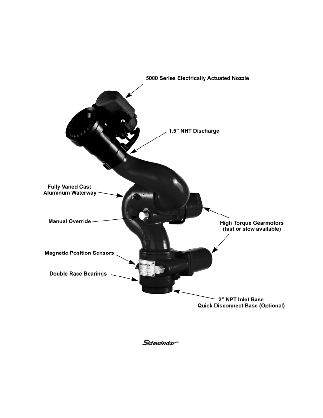
Figure 1
8494
2
Monitor
Page 7
II. SYSTEM COMPONENT DESCRIPTIONS
A. Monitor
The Monitor is specially designed to mount on the front bumper of off-road or wildland
fire fighting apparatus. It rotates either 180° or 334° to spray straight ahead or to either side for use in
fighting forest, grass, range, brush and similar fires. In addition, because is controlled
from inside the cab, risk to firefighters is significantly reduced.
The
gears and motors that are completely enclosed and sealed for maximum protection from the elements.
The
superior fire streams. Water supply is provided through the monitor base by 2” National Pipe Thread
connection. The discharge nozzle connection is a 1½” National Hose Thread. Nozzle stream direction
is controlled by two permanent magnet type gear motors, one controlling rotation about the axis of the
water inlet, and the other controlling nozzle elevation and depression.
An optional 2.0” electric valve kit is available to allow the user to control water flow directly from the
operator in the cab of the truck.
features durable Elk-O-Lite® construction combined with rugged, stainless steel
has a flow efficient 2.0” vaned waterway to minimize turbulence and provide
control box. This enables “pump and roll” functionality with complete control by the
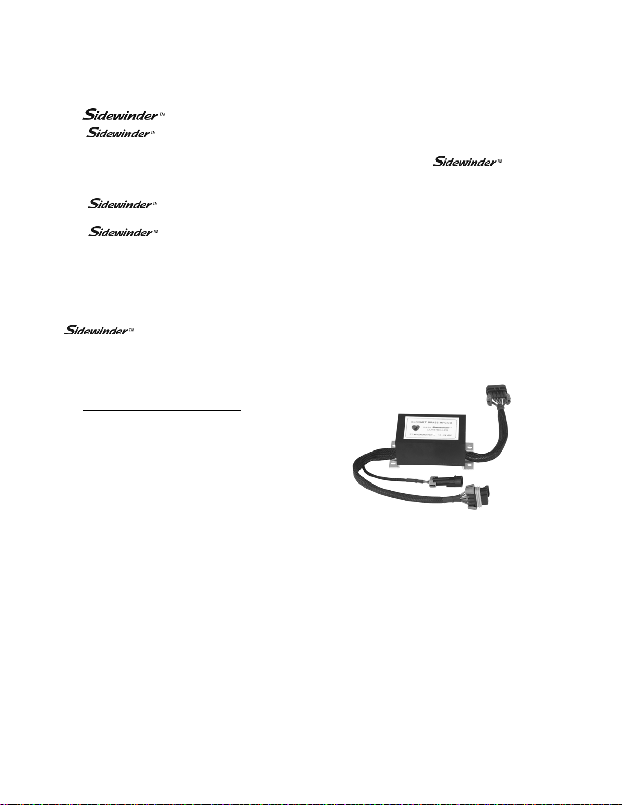
B. 81713000 Control Module
The control module is completely encapsulated in
epoxy for maximum protection from the elements.
The module has reverse polarity protection to
prevent damage to the electronic components. The
module uses feedback from Hall effect sensors to
determine when the monitor travel limits have
been reached. It also uses dynamic braking to stop
the motors for precision motion control.
Figure 2
81713000 Control Module
3
Page 8
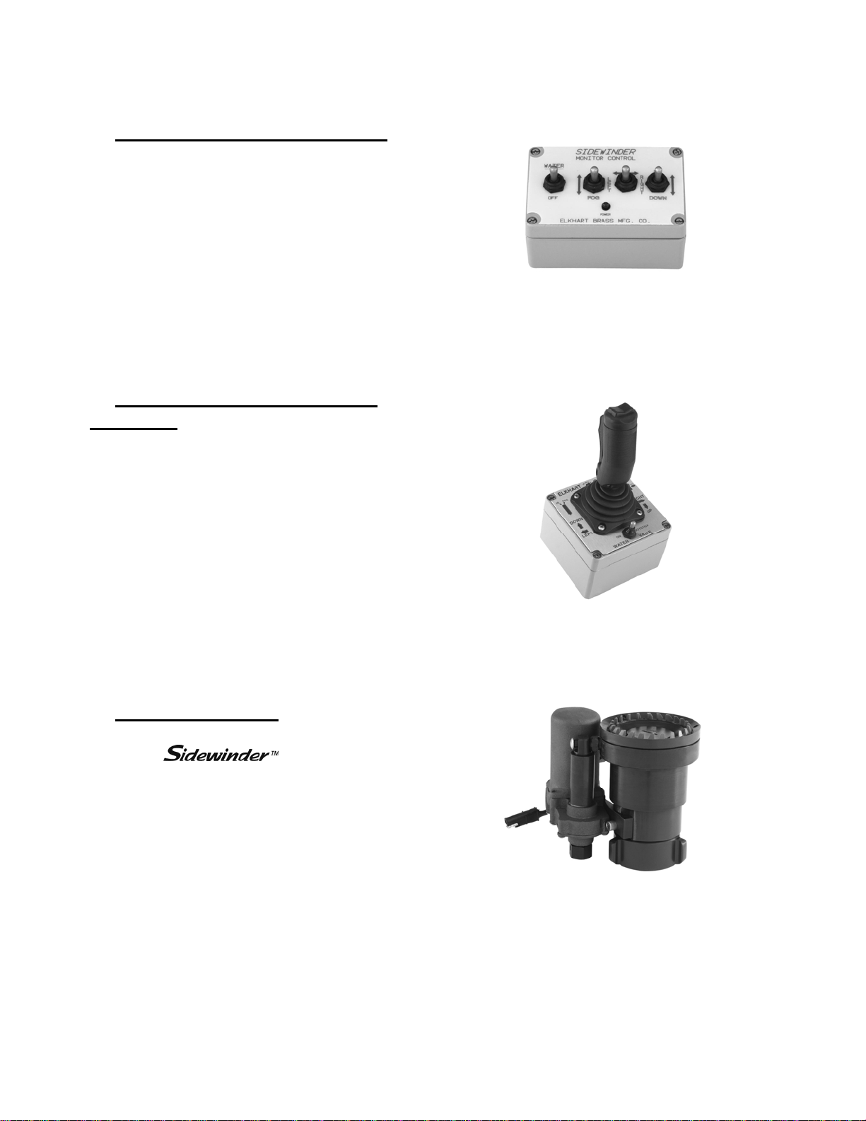
C. 81122001 Standard Control Box
The standard control box consists of a weathertight enclosure with toggle switches that is suitable
for mounting inside or outside the apparatus. The
toggle switches control the water supply (On-Off),
monitor direction (Left-Right and Up-Down), and
nozzle pattern (Straight Stream-Fog).
D. 81172001 Joystick Control Box
(Optional)
The joystick control box is suitable for mounting
inside the apparatus cab. The joystick controls all
four functions. The water supply is controlled
with a trigger switch on the front of the joystick.
The water can also be run continuously by
activating the toggle switch mounted on the
enclosure. Nozzle pattern is changed using the
rocker switch on the top of the joystick. The
monitor direction is changed by moving the
joystick in the desired direction.
Figure 3
81122001 Standard Control Box
Figure 4
81172001 Joystick Control Box
E. 5000 Series Nozzles
Three constant flow electric nozzles are offered
with the
ranging from 15 to 350 GPM. The nozzle pattern
is electrically actuated and controlled by the
monitor control box.
Available in 12 VDC or 24 VDC.
5000-04; 15, 30, or 45 GPM
5000-14; 60, 95, 125, or 150 GPM
5000-24; 175, 200, 250, or 350 GPM
monitor, with flows
4
Figure 5
5000-24 Electrically Actuated Nozzle
Page 9
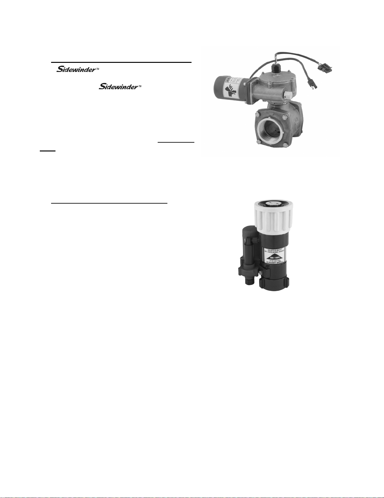
F. 81181001 Water Valve Kit (Optional)
The water valve kit provides a
convenient remote on-off control of the water
supply to the 8494 . This allows the
operator complete control of the unit from the
safety of the vehicle cab. It also allows a “pump
and roll” capability. The water valve motor
prevents water hammer, yet closes quickly enough
to help preserve the limited on-board water supply.
The 81181001 Water Valve Kit is for 12VDC use
only. The 81298001 Water Valve Kit (24V) is
available for use with 24VDC systems. It includes
a 24-12 volt converter to power the water valve
and control module.
G. SM-10FE De/Anti-Icing Nozzle
Designed for the aircraft deicing industry, this
nozzle has been designed for use with type 1 deicing, type 2 anti-icing, or type 4 anti-icing fluids.
The SM-10FE has Viton® O-rings to withstand the
use of the Ethylene Glycol and Propylene Glycol
solutions used to de-ice aircraft. The nozzle is
constant gallonage at pressures below 90 Psi and
becomes automatic at 95 Psi. It is designed to
deliver 20 GPM at 50 Psi and 30 –120 GPM from
90-110 Psi.
Available in 12 VDC or 24 VDC.
Figure 6
2920E Electrically Actuated Valve
Figure 7
SM-10FE De/Anti-Icing Nozzle
5
Page 10

III. CONTROL SYSTEM SPECIFICATIONS
A. Monitor Controller Specifications
• Power requirements
• Maximum Continuous Amps
• Peak Amps
12VDC - 11VDC to 14VDC
24VDC - 22 VDC to 27 VDC
12VDC - 5 A
24VDC – 2.5 A
12VDC - 14 A
24VDC - 7 A
• Operating temperature range
• Required inline fuse
-40°F to 176°F (-40°C to 80°C)
12VDC - 10 A
24VDC - 5 A
B. Optional Valve Controller Specifications
• Power requirements
• Maximum Continuous Amps
• Peak Amps
• Operating temperature range
• Required inline fuse
(One fuse can be used to protect both the
monitor and valve controllers.)
Shock:
• 30 G's (55 Hz. @ .2 inch double amplitude)
Vibration:
• 15.5 G's (55 Hz. @ .05 inch double amplitude) continuous operation
Environmental:
• NEMA 4 rating (except 81172001 Joystick Assembly and 81122001 Switch Box Assembly) (must withstand a 1
inch stream of water (65 gpm) from a distance of ten feet for five minutes, with no water entering the enclosure).
12VDC - 11VDC to 14VDC
24VDC - 22 VDC to 27 VDC
12VDC - 5 A
24VDC – 2.5 A
12VDC - 14 A
24VDC - 7 A
-40°F to 176°F (-40°C to 80°C)
12VDC - 10 A
24VDC - 5 A
6
Page 11

IV. INSTALLATION INSTRUCTIONS
A. Component Mounting
1. Monitor
Before mounting the Sidewinder
envelopes are clear of all obstructions. See Figure 8 and Figure 9 for envelope dimensions. The
rotation limits are determined by the magnet locations in the monitor body, and cannot be adjusted.
(Exception: A 334° monitor can be made into a 180° monitor by adding two magnets through an
access hole).
®
monitor, ensure that both the horizontal and vertical rotation
Figure 8
Horizontal Rotation Envelope
Vertical Rotation Envelope
Figure 9
1) Ensure the left-right and up-down motors are aligned as shown in Figure 8.
®
2) Mount the Sidewinder
monitor to a securely mounted 2.0” NPT threaded pipe (additional
support may be necessary). The monitor can be mounted in any orientation, although some
orientations will reverse the directions of movement relative to the control box.
3) Ensure that all of the electrical connections have been disconnected.
4) Apply a suitable thread sealant, thread the monitor onto the pipe connection, and tighten it
securely with a strap wrench. Make sure the motor on the monitor base is facing away from the
intended center of rotation. The rotation limits are determined by the magnet locations in the
monitor body, and cannot be adjusted. (Exception: A 334° monitor can be made into a 180°
monitor by adding two magnets through an access hole).
5) Reconnect the electrical connections according to Figure 19 and Figure 20. Check all of the
electrical connections to make sure they are tight. Allow enough slack in the monitor harness to
permit travel to the limits allowed by the controller without straining the wires.
7
Page 12

2. 81713000 Control Module
The 81713000 control module is a rugged, watertight unit, allowing it to be installed anywhere within
reach of the wiring harnesses. The cables should be routed away from any heat sources, and be
protected from sharp corners. They should be tied down securely to prevent fretting or fraying due to
vehicular vibrations. Securely mount the module to the vehicle. Connect the monitor connector to the
monitor wiring harness. Connect the control connector to the wiring harness coming from the control
box (or optional joystick). Connect the power connector to the fused power source. The control
module can be supplied by either a 12 VDC or 24 VDC power source determined by monitor voltage
requirements. See Section III.A. Monitor Controller Specifications.
PT #81713000 REV REL 12-24 VDC
81713000 Control Module Mounting Layout Drawing
B
Figure 10
3. 81122001 Control Box & 81172001 Joystick Control Box (Optional)
The control boxes can be mounted using the mounting holes provided inside of the boxes. Any
modification of the boxes themselves will void the Elkhart Brass warranty on the device. The
connector attaching the wiring harness to the control box should be inserted straight into the
mating connector on the box. Be sure to align the key with the keyway. There should be no need
to force the connectors together. The locking ring on the connector will give a positive indication
when it has locked to the connector body.
The control boxes should be mounted in a location where the wiring harness connecting to the box
will have 2 - 3 inches of straight cable before beginning a bend (see Figure 13). This will remove
stress from the connector, and prevent damage.
8
Page 13

Figure 11
81122001 Control Box Mounting Layout
Figure 12
81172001 Joystick Mounting Layout
Figure 13
81172001 Joystick Cable Allowance
9
Page 14

4. 81181001 Water Valve Kit (Optional)
The 81181001 Valve Kit is for use with 12V DC systems ONLY. To use the valve kit with a 24V
system an 81298001 Water Valve Kit (24V) should be used.
Warning:
Using the 81181001 Water Valve Kit on a 24VDC system will damage the position sensors and burn
out the motor. Elkhart Brass P/N 81298001 Water Valve Kit (24V) is the 24V replacement for the
81181001 Water Valve Kit.
Install the valve inline with the monitor. Mount the 81196000 or 81294001 control
module to the apparatus. The cables should be routed away from any heat sources, and be protected
from sharp corners. They should be tied down securely to prevent fretting or fraying due to vehicular
vibrations. Several optional cable lengths are available for the valve controller to allow it to be
mounted in a convenient location. Connect the motor power and sensor lead to the valve harness. See
Section III.B. Optional Valve Controller Specifications. Wire an inline fuse to the positive (red) lead
of the control module (the same fuse that was used for the 81713000 can be used here). Connect the
control connector to the free connector on the control harness.
Control Harness to Valve Module
Extension Cables
Part No. Length
36779100 1ft
36779200 3ft
36779300 5ft
36779400 8ft
36779500 10ft
36779800 25ft
10
Page 15

#10/5 MM
Screw Max.
Figure 14
81196000 12 VDC Valve Control Module Layout
Power
Connector
Monitor
Connector
#10/5 MM
Screw Max.
Control
Connector
Figure 15
81294001 24 VDC Valve Control Module Layout
11
Page 16

V. OPERATING INSTRUCTIONS
A. Normal Operation
1. 81122001 Standard Control Box
The monitor and nozzle are controlled with three toggle switches at each control point. These
switches are marked “STRT-FOG”, “LEFT-RIGHT”, and “UP-DOWN”. The switches are of the
three position, momentary contact, center-off type. Simply push and hold the switch(es) to move
the monitor to the desired stream direction, or to adjust the nozzle to the desired spray pattern.
Release the switch when the proper stream position or spray pattern is achieved. To flush the
nozzle press the “FOG” switch. The nozzle will move to the wide fog position and continue on to
the flush position. Use caution when the nozzle is in the wide fog position to not accidentally
place the nozzle in the flush position. The 5000 Series and SM-10FE nozzles have a unique ball
screw drive that allows motor to “free wheel” at the end of pattern travel in either the straight
stream or wide fog positions. No slip clutch or current limiting feature is used with these nozzle
drives. To flow water with the optional 81181001 or 81298001 Water Valve kits, place the
“WATER” switch to water. This will completely open the valve. To close the valve place the
“WATER” switch to off.
2. 81172001 Joystick Control Box
With the 81172001 Joystick Control Box, the monitor, nozzle and valve are controlled with the
joystick and accompanying switches. Simply push and hold the joystick to move the monitor to
the desired stream direction. Release the switch when the proper stream position is achieved. The
nozzle spray pattern is controlled using the rocker switch on the top of the joystick. To flush the
nozzle press the “FOG” switch. The nozzle will move to the wide fog position and continue on to
the flush position. Use caution when the nozzle is in the wide fog position to not accidentally
place the nozzle in the flush position. To continuously flow water with the optional 81181001 or
81298001 Water Valve kits, place the water valve switch to “ON”. This will completely open the
valve and keep it open regardless of the lever position on the joystick. To close the valve place the
water valve switch to “JOYSTICK” and let go of the joystick lever. To flow water for short
durations leave the water valve switch in the “JOYSTICK” position and operate the valve with the
lever on the front of the joystick. The valve will open as long as the lever is held in. When it is
released, the valve will close.
B. Manual Override
In the event of power failure to one or more motors, the motor(s) may be actuated manually. To
operate a function manually, simply apply a 3/4" ratcheting type wrench (either socket type or
ratcheting box end type) to the hex fitting on the motor shaft extension. The left-right and up-down
functions can be overridden much easier if the motor wire connector is unplugged from the control
harness.
Caution:
Do not use impact drivers to operate the manual override nuts. Serious damage to the motor gearheads
will result.
12
Page 17

VI. MAINTENANCE
A. Preventive Maintenance
The complete monitor and control system should be inspected during each apparatus check. Careful
inspection for damage to the monitor or nozzle is especially important after use of the
Monitor in emergency operations.
1. Operate each function (left-right, up-down, strt-fog) from each control point.
2. Flow water to check the nozzle pattern. If the pattern is disrupted, use the nozzle flush feature
to clear the debris. If the obstruction still remains, remove the nozzle and check for debris
lodged between the nozzle stem and body.
3. During nozzle flow test, inspect monitor swivel joints for leaks.
4. Inspect all exposed wiring for signs of damage.
Note: Although grease fittings are provided for the up-down and left-right gear cases, routine
greasing should not be necessary. If the monitor is exposed to high level of radiant heat for a
prolonged period, it may be possible for the factory grease to thin and run out of the gear cases. In
such an event, fresh grease should be applied. It is recommended that Mobilith AW2 grease be used
to lubricate the monitor gearing.
13
Page 18

VII. MONITOR & NOZZLE HYDRAULIC DATA
5000-04 Flow Data (GPM)
PSI
40
50
75
100
125
150
175
200
40
50 48 20 11 65 30 15 69 32 17
75 56 22 14 70 35 16 75 37 18
100582415814117834421
125612617854421914623
150632819904723964825
175653121914825985026
200 66 32 22 92 49 26 101 51 28
15 GPM Stem
9
11
12
15
17
18
20
22
15 GPM Stem
SS N. FOG W. FOG SS N. FOG W . FOG SS N. FOG W . FOG
30 GPM Stem
20
22
26
30
34
37
39
41
45 GPM Stem
32
35
40
45
49
52
56
58
5000-04 Reach Data (ft)
30 GPM Stem 45 GPM Stem
5000-14 Flow Data (GPM)
60 GPM Stem 95 GPM Stem 125 GPM Stem 150 GPM Stem
40
50
75
100
125
150
175
200
38 63 82 97
43 68 91 107
51 83 110 132
60 95 125 150
68 107 140 169
73 115 153 182
79 126 165 198
85 134 177 212
5000-14 Reach Data (ft)
60 GPM Stem 95 GPM Stem 125 GPM Stem 150 GPM Stem
SS N. FOG W. FOG SS N. FOG W . FOG SS N. FOG W . FOG SS N. FOG W. FOG
40 69 38 31 77 40 29 78 44 32 80 46 34
50 76 41 33 86 41 30 86 48 36 89 51 37
75 89 44 35 101 46 33 103 55 37 108 53 43
100 96 49 41 111 55 36 113 62 44 124 56 46
125 104 55 43 118 59 40 121 67 49 138 58 48
150 110 61 47 126 64 44 128 71 52 148 60 51
175 115 66 51 130 67 47 138 77 56 156 62 52
200 124 71 58 138 70 51 146 84 59 162 64 55
Figure 16
5000-04 and 5000-14 Flow and Reach Data
14
Page 19

175 GPM Stem
111
40
50
75
100
125
150
175
200
175 GPM Stem 200 GPM Stem 250 GPM Stem 350 GPM Stem
SS N. FOG W. FOG SS N. F OG W. FOG SS N. FOG W. FOG SS N. FOG W. FOG
88 47 32 91 51 34 91 53 35 97 57 39
40
50
98 51 34 101 54 36 102 56 40 108 61 43
75
114 59 36 117 61 40 118 62 43 126 67 47
100
126 69 39 132 73 44 136 75 48 142 70 52
125
141 76 44 148 78 48 152 79 51 160 86 55
150
152 81 48 159 83 52 164 83 54 173 89 59
175
165 88 51 - - - 179 89 58 188 95 63
178 95 54 - - - 193 95 62 203 102 67
200
5000-24 Flow and Reach Data
126 172 220
124 141 192 240
150 173 230 289
175 200 250 325
192 224 279 362
210 245 306 398
231 265 331 429
247 283 353 459
5000-24 Flow Data (GPM)
200 GPM Stem 250 GPM Stem 350 GPM Stem
5000-24 Reach Data (ft)
Figure 17
Interpreting Flow Data
The following graphs offer the pressure losses for the monitor (and other devices) in terms of
Total Static Pressure Drop. This Total Static Pressure Drop can be found by measuring the
difference between the static inlet pressure and the static outlet pressure. The static
pressure at either of these points can be found using a simple pressure gauge. An
illustration of this method can be seen below.
In mathematical terms, the Total Static Pressure Drop is the change in Velocity Pressure
plus Friction Loss. The change in Velocity Pressure results from the change in velocity of
water caused by the change in the cross section of a waterway. Friction Loss results from
the drag and sidewall interference of the water through a device. A simple equation can be
seen below.
15
Page 20

Δ
ΔPS = HF + ΔP
ΔPS = Total Static Pressure Drop
H
= Friction Loss
F
P
= Velocity Pressure Loss
V
In the firefighting industry, the terms Total Static Pressure Drop and Friction Loss tend to be
used interchangeably. However, these are significantly different measurements. This
misconception could ultimately lead to lower than anticipated performance from equipment.
When designing a system and determining performance, Total Static Pressure Drop is
the value that should always be used. The Friction Loss curve is also supplied in order to
make a comparison with competitor products that may only supply Friction Loss curves. If
there are any further questions regarding this matter, please contact Elkhart Brass.
8494 Sidewinder Losses
2.0" Inlet & 1.5" Outlet
50
45
40
35
30
25
Pressure (PSI)
20
15
10
5
0
0 50 100 150 200 250 300 350 400 450
Flow Rate (GPM)
Total Static Pressure Drop Friction Loss
Figure 18
8494 Monitor Friction Loss
16
Page 21

VIII. PARTS DRAWINGS
Figure 19
8494 12VDC Layout
17
Page 22

Figure 20
8494 24VDC Layout
18
Page 23

Figure 21
5000-04 Parts Drawing
19
Page 24

Figure 22
5000-14 Parts Drawing
20
Page 25

Figure 23
5000-24 Parts Drawing
21
Page 26

8494
22
Page 27

IND.# PART # QTY PART DESCRIPTION
1 17908001 1 MONITOR OUTLET BODY
2 15027000 144 BALLS-0.250 DIA. SS (36 PER RACE)
3 57502000 2 O-RING AS 568-148F (2.737 ID X 0.103 C/S)
4 63687000 5 SET SCREW 0.312-18 X 0.187 LG BLK NYLON
5 31011000 2 GREASE FITTING (SS)
6 51248000 2 ROLL PIN 0.125 DIA. X 0.625 LG SS
7 47652001 2 OVER-RIDE NUT
8 65140000 1 SCREWS #6-32 X 0.750 LG SOC BTN HD SS
9 23572000 1 CLAMP LOOP (NYLON) 0.140 HOLE
10 65139000 3 SCREWS #6-32 X 0.625 LG SOC BTN HD SS
11 71176000 3 WASHER - #6 SS
12 65572000 4 SPACER - SENSOR
13 65104000 2 POSITION SENSOR
14 18219001 1 MONITOR INLET BODY
15 44339000 1 SERIAL NO./IDENTIFICATION PLATE
16 61215100 4 DRIVE SCREW #4 X 0.187 RND HD SS
17 17975001 1 MONITOR BASE (2.0 NPT FEMALE)
18 64072000 8 CAP SCREWS #10-32 X 0.500 LG SOC HD SS
19 81119001 2 MOTOR ASSY (12 VDC SLOW)
19 81147001 2 MOTOR ASSY (12 VDC FAST)
19 81207001 2 MOTOR ASSY (24 VDC SLOW)
19 81240001 2 MOTOR ASSY (24 VDC FAST)
20 36791200 1 QUICK CONNECT HARNESS EXTENSION
21 63797000 1 SCREW #10-32 X 0.250 LG SLT PAN HD SS
22 23570000 1 CLAMP LOOP CUSHIONED
23 36833100 1 MONITOR CONTROL HARNESS
24 23571000 2 CLAMP LOOP (NYLON) 0.210 HOLE
25 71515000 4 THRUST WASHER 1/4
26 17701000 2 THRUST BEARING 1/4
27 65201000 2 SET SCREW #10-32 X 0.125 LG SOC HD SS
28 20991001 2 COUPLING
29 65219000 2 SET SCREW #10-32 X 0.187 LG SOC HD SS
30 51071000 2 SOLID PIN (DRIVE LOCK E) 0.125 DIA X 0.875LG
31 63935001 2 WORM SHAFT SS
32 63601001 2 SPACER
33 71516000 4 THRUST WASHER 5/16
34 17702000 2 THRUST BEARING 5/16
35 57380000 2 O-RING AS 568-008 (0.176 ID X 0.070 C/S)
36 46054000 4 MAGNETS
OPTIONAL QUICK CONNET CPLG ASSY
37 81342001 1 QUICK CONNECT COUPLING
OPTIONAL FOR USE WITH P/N 81342001 QUICK CONNECT ADAPTER
38 81342051 1 DUST PLUG ASSY WITH CHAIN
8494 SIDEWINDER MONITOR PART LIST
23
Page 28

Elkhart Brass Mfg. Co., Inc.
Mailing Address:
P.O. Box 1127
Elkhart, IN 46515 USA
Shipping Address:
1302 W. Beardsley Ave.
Elkhart, IN 46514 USA
Tel. 1-574-295-8330
1-800-346-0250
Fax 1-574-293-9914
e-mail: info@elkhartbrass.com
www.elkhartbrass.com
98275000 Rev. C
 Loading...