

Page 1
E
LLKKHHAARRTT
E
1302 WEST BEARDSLEY AVENUE • P.O. BOX 1127 • ELKHART IN 46515 • (574) 295-8330 • FAX (574) 293-9914
B
RRAASSSS
B
M
M
G
FFG
.
C
.
C
O
O
..,
,
I
I
NNC
C
..
Installation, Operating, & Maintenance
Instructions
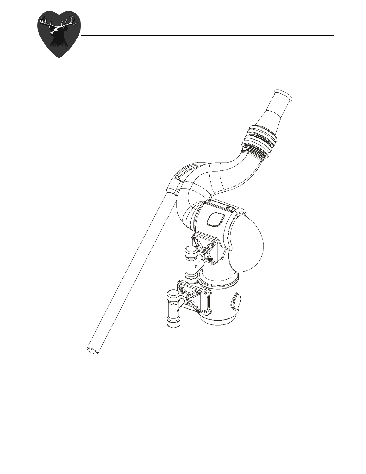
Model 8392-02 Sidewinder (Brass)
Model 8492-02 Sidewinder (Aluminum)
98323000 Rev. Rel
Page 2

Table of Contents
I. PRODUCT SAFETY ................................................................................................................... 1
II. INSTALLATION INSTRUCTIONS............................................................................................ 2
III. OPERATING INSTRUCTIONS............................................................................................. 2
IV. MAINTENANCE & INSPECTION......................................................................................... 2
V. PARTS DRAWINGS................................................................................................................... 2
VI. MONITOR & STREAM SHAPER ......................................................................................... 3
1. INTERPRETING FLOW DATA ....................................................................................................... 3
2. MONITOR AND STREAM SHAPER HYDRAULIC DATA................................................................. 3
Page 3

I. PRODUCT SAFETY
Important:
Before installing and operating this equipment, read & study this manual
thoroughly. Proper installation is essential to safe operation. In addition, the
following points should be adhered to in order to ensure the safety of equipment
and personnel:
1. All personnel who may be expected to use this equipment must be
thoroughly trained in its safe and proper use.
2. Before flowing water from this device, check that all personnel (fire
service and civilian) are out of the stream path. Also, check to make sure
stream direction will not cause avoidable property damage.
3. Become thoroughly familiar with the hydraulic characteristics of this
equipment, and the pumping system used to supply it. To produce effective
fire streams, operating personnel must be properly trained.
4. Open water valve supplying this equipment
slowly, thus preventing possible water hammer occurrence.
5. After each use, and on a scheduled basis, inspect equipment per
instructions in
Maintenance & Inspection on page 2.
slowly, so that the piping fills
Warning: The piping must be able to withstand a horizontal reaction force of at
least 500 lbs at the height of the discharge elbow pivot center and from any angle of
rotation that the monitor is capable of turning. Serious injury to personnel and equipment
can result from improper installation.
1
Page 4

II. INSTALLATION INSTRUCTIONS
Apply an appropriate thread sealant to the 2” NPT male thread or nipple.
Thread the monitor base onto the male thread or nipple and tighten
securely. Install nozzle onto 1.5 NH threads on monitor discharge. (use
of a stream shaper is recommended when using a smooth bore nozzle.)
III. OPERATING INSTRUCTIONS
Turn both left/right and up/down lock handles counterclockwise to
disengage locks. Use the tiller handle to direct the monitor discharge.
To secure the monitor in a desired left/right and up/down position, turn
both lock handles clockwise to engage locks. The monitor must never be
left unattended with out engaging both locks.
IV. MAINTENANCE & INSPECTION
The monitor should be inspected regularly. Careful inspection for damage to
the monitor or nozzle is especially important after use in emergency
operations.
Flow water to check nozzle pattern. If pattern is disrupted, remove nozzle and
check for debris lodged between the nozzle stem and body, or in the stream
shaper inlet.
During nozzle flow test, inspect monitor swivel joints for leaks.
Note: Although grease fittings are provided for the up-down and left-right
rotation joints, routine greasing should not be necessary. If the monitor is
exposed to a high level of radiant heat for a prolonged period, it may be
possible for the factory grease to thin and run out. In such an event, fresh
grease should be applied. Pump fresh grease into each rotation joint until the
old grease is purged and fresh grease comes out. Rotate the joint 45 degrees
and repeat until the entire range of movement has been covered
V. PARTS DRAWINGS
Please visit the Elkhart Brass website for parts drawings of both monitors.
2
Page 5

VI. MONITOR & STREAM SHAPER
1. Interpreting Flow Data
The following graphs offer the pressure losses for the monitor (and other devices) in terms
of Total Static Pressure Drop. This Total Static Pressure Drop can be found by measuring
the difference between the static inlet pressure and the static outlet pressure. The static
pressure at either of these points can be found using a simple pressure gauge. An
illustration of this method can be seen below.
In mathematical terms, the Total Static Pressure Drop is the change in Velocity Pressure
plus Friction Loss. The change in Velocity Pressure results from the change in velocity of
water caused by the change in the cross section of a waterway. Friction Loss results from
the drag and sidewall interference of the water through a device. A simple equation can be
seen below.
In the firefighting industry, the terms Total Static Pressure Drop and Friction Loss tend to be
used interchangeably. However, these are significantly different measurements. This
misconception could ultimately lead to lower than anticipated performance from equipment.
When designing a system and determining performance, Total Static Pressure Drop
is the value that should always be used. The Friction Loss curve is also supplied in order
to make a comparison with competitor products that may only supply Friction Loss curves.
If there are any further questions regarding this matter, please contact Elkhart Brass.
ΔPS = HF + ΔP
ΔPS = Total Static Pressure Drop
H
= Friction Loss
F
= Velocity Pressure Loss
ΔP
V
2. Monitor and Stream Shaper Hydraulic Data
Please visit the Elkhart Brass website for performance charts for the monitors
and stream shapers.
3
Page 6

Elkhart Brass Mfg. Co., Inc.
Mailing Address:
P.O. Box 1127
Elkhart, IN 46515 USA
Shipping Address:
1302 W. Beardsley Ave.
Elkhart, IN 46514 USA
Tel. 1-574-295-8330
1-800-346-0250
Fax 1-574-293-9914
e-mail:
info@elkhartbrass.com
www.elkhartbrass.com
 Loading...