

Page 1

Operating & Maintenance Instructions
Model 8397 2.0
Non Break-Apart
Portable Monitor & Accessories
98276000 REV C
1302 West Beardsley Ave • Elkhart, IN 46514 • 1-574-295-8330 • 1-800-346-0250
© 2014 Elkhart Brass Mfg. Co., Inc. • WWW.ELKHARTBRASS.COM
Page 2

Table of Contents
I. PRODUCT SAFETY ................................................................................................................................... 3
II. PRODUCT DESCRIPTION ......................................................................................................................... 5
A. 8397 Monitor Assembly ......................................................................................... 5
B. Available inlet Connections ............................................................................................................ 6
C. 8297MB Storage Bracket ............................................................................................................... 6
D. 81460001 Anchor Kit ..................................................................................................................... 7
III. OPERATION ........................................................................................................................................... 8
A. Monitor Setup & Operation ............................................................................................................ 8
IV. MAINTENANCE ................................................................................................................................... 10
A. Maintenance Procedures for 8397 Monitor Assembly ......................................... 10
1. After Each Use: ....................................................................................................................... 10
2. As Needed: .............................................................................................................................. 10
3. As Needed: .............................................................................................................................. 11
V. MONITOR & STREAM SHAPER HYDRAULIC DATA ............................................................................... 12
2
Page 3

I. PRODUCT SAFETY
Important:
Before operating this equipment, read & study this manual thoroughly. Familiarity with
the proper use of this product is essential to safe operation. In addition, the following
points should be adhered to in order to ensure the safety of equipment and personnel:
All personnel who may be expected to use this equipment must be thoroughly trained in its safe
and proper use.
Before flowing water from this device, check that all personnel (fire service and civilian) are
out of the stream path. Also, check to make sure stream direction will not cause avoidable
property damage.
Become thoroughly familiar with the hydraulic characteristics of this equipment, and the
pumping system used to supply it. To produce effective fire streams operating personnel must
be properly trained.
Open water valve supplying this equipment slowly, so that piping and hose lines fill slowly,
thus preventing possible water hammer occurrence.
After each use, and on a scheduled basis, inspect equipment per instructions in section IV.
Never exceed 1250 GPM flow.
Never lower the discharge below the safety stop. The reaction force of the nozzle stream may
cause the monitor to slide.
Always engage left/right lock when un-manned or not in use.
Always secure the monitor with the safety strap.
Never attempt to move the monitor while flowing water.
Always inspect the ground spikes for damage after each use.
Master streams are extremely powerful. Therefore, great care must be taken in directing such
streams to avoid injury to personnel and unwanted damage to property.
3
Page 4
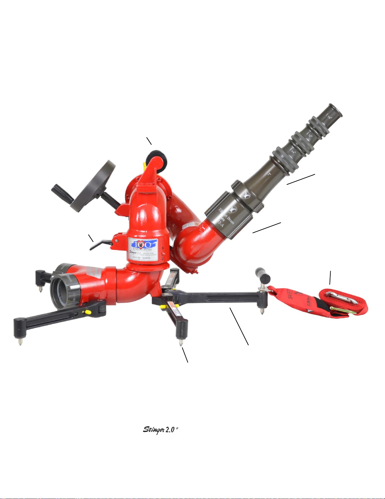
Horizontal Rotation Lock
Carbide Tipped
Ground Spikes
Forged Aluminum Legs
Safety Strap
Stream Shaper
Quad Stacked
Smooth Bore Tips
Carrying Handle
Fig. 1
8397 W/ 282-A Stream Shaper
& ST-194 Stacked Tips
4
Page 5

II. PRODUCT DESCRIPTION
A. 8397 Monitor Assembly
The 8397 Stinger 2.0® Portable Monitor is a lightweight versatile monitor. The highly efficient cast
aluminum waterway contains a central vane to minimize large-scale turbulence and provide superior
fire streams. The vertical stream direction is controlled by a handwheel driving a worm gear. The
horizontal stream direction is controlled by disengaging the left-right lock and moving the return bend
by hand. The maximum monitor flow capacity is 1250 gallons per minute with the single inlet bases
(the clappered Siamese inlet is rated at 1000 GPM).
8397 Stinger 2.0® monitors are normally supplied with the 282A and ST-194 Stacked Tip combination.
The SM-1250 constant pressure (automatic) type master stream nozzle is also available for
use with the 8397 Stinger 2.0®.
The following additional features are also provided in the 8397 Stinger 2.0® monitor:
Enclosed Gearing
Fully enclosed worm gearing drives the vertical travel. The gearing runs in a clean grease filled
environment isolated from dirt, grit, ice, or anything else that might interfere with exposed
gearing.
Elevation Safety Stop Pin
The stop pin alerts the operator when the elevation has reached its lowest point (35 degrees
above horizontal) without activating the manual override. The manual over-ride should only be
used when advancing a hose line from the 8397 Stinger 2.0® monitor’s discharge. Using the
over-ride while in portable mode can cause serious injury or death to nearby personnel.
Left-Right Lock Lever
The left-right lock is designed to engage and disengage quickly. The left-right lock lever
visually indicates the status of the lock.
Forged Aluminum Support Legs
The folding support legs are forged aluminum for ultra high strength and light weight. The
folding legs are designed to be easily rotated from the stored position to the extended and
locked position and back again. The spring-loaded carbide ground spikes are very hard and very
sharp, important factors in the prevention of sliding under flow. With the legs folded the 8397
Stinger 2.0® can be easily stored in a compartment or in our 8297 MB storage bracket preconnected and ready to go!
Two Carrying Handles
There are two convenient handles to make carrying the lightest 1250 GPM portable monitor
even easier.
5
Page 6

C. 8297MB Storage Bracket
The 8297MB is an optional, lightweight bracket
that is designed to hold the 8397 Stinger 2.0®
securely in place while in storage. A single release
lever allows for fast and efficient removal of the
unit from the storage bracket. The bracket can be
mounted either horizontally or vertically.
(Not intended to be used while flowing water.)
Fig. 4
8297MB Storage Bracket
B. Available inlet Connections
There are six inlet connections available:
1. Two 2.5” clappered female swivel
inlets
2. One 3.5” swivel inlet
3. One 4.0” swivel inlet
4. One 4.5” swivel inlet
5. One 4.0” Storz inlet
6. One 5.0” Storz inlet
Fig. 2
5" Storz Base
Fig. 3
Dual 2.5" Siamese Base
6
Page 7

D. 81460001 Anchor Kit
The anchor kit is used to safely secure the monitor
in place with a steel stake. The 8397 Stinger 2.0®
should always be anchored using the attached
safety strap when it is in the portable mode. The
kit also includes a Nupla® 4lb. hammer with safety
grip fiberglass handle, and a nylon carrying bag.
Fig. 5
81204001 Anchor Kit
7
Page 8

III. OPERATION
4. Aim the monitor nozzle towards the intended
target, (if necessary, first release the left/right
lock as shown in Figure 7), and engage the
left-right lock as shown in Figure 6.
Figure 6
Locked Position
Figure 7
Un-locked Position
A. Monitor Setup & Operation
Determine the monitor’s location (keeping in mind the need for a substantial stationary object to
which the safety strap can be attached that is in line with the intended stream direction). Remember
that the nozzle reaction force can be as high as 900 lbs.
1. Prepare the monitor for use by simply rotating each of the four folding legs into its locked
position, starting with the two rearmost legs. It is very important that the legs be in the
locked position prior to initiating water flow. (To fold the legs for storage start with the
front legs first. With two fingers, one on each side of the leg, pull the yellow pin towards the
spiked end of the leg until it can be rotated forward to the stored position. There is a set
screw in the leg bracket that serves as a detent for the lock pin when the legs are in the
stored position. The rear legs can then be folded using the same procedure.)
2. Anchor the monitor with the safety strap. The safety strap should be attached to the monitor
at the carrying handle support post on the front center leg and secured around a substantial
stationary object. The stationary object, such as a stake, parking meter, fence post, etc.,
should be positioned between the 8397 Stinger 2.0® monitor and the intended target. The
monitor’s center front leg should point directly at the stationary object and intended target.
The monitor should never be used with any slack in the safety strap. If no suitable object is
available, the Elkhart 81460001 anchor kit must be used.
3. Attach the hose(s) to the monitor’s inlet connection(s). To minimize the possibility of the
charged hose line(s) moving the monitor, the supply hose(s) should be kept straight in line
with its respective inlet port for a distance of at least ten feet.
5. Charge the hose lines slowly to prevent water hammer.
6. Engage the left-right lock to hold the monitor in position. Never leave the monitor
unattended while the left-right lock is disengaged.
8
Page 9

8. The only case in which the monitor discharge
should be lowered below the range allowed by the
safety stop is to advance a hose line from the
monitor discharge. The water supply to the
monitor must be shut down and the nozzle and
stream shaper removed. While pulling up on the
ring attached to the safety stop pin the monitor
discharge can be lowered past the 35 degree limit.
(see Figure 8) The ring can then be released.
Attach the hose line and nozzle and remember to
charge the lines slowly. When finished remove the
hose from the monitor’s discharge and raise the
monitor discharge to its upper limit. The springloaded safety stop will reset itself. Reattach the
stream shaper and nozzle.
Figure 8
7. The nozzle stream elevation can be adjusted within a range of 35 degrees above horizontal
to 75 degrees above horizontal. This is the range allowed by the safety stop. A positive stop
will be felt through the Handwheel at each end of the travel limit. Do not attempt to go past
these limits by applying more force to the Handwheel as it may result in gear damage. Turn
the Handwheel clockwise to lower the discharge and counter-clockwise to raise the
discharge.
Warning:
Never lower the discharge elbow below the angle allowed by the vertical safety stop when using the
8397 Stinger 2.0® portable monitor. If the discharge is lowered below the safety stop, the nozzle
reaction force will cause the monitor and hose lines to slide. Serious injury or death could occur if this
warning is not followed.
9. To turn the monitor to the left disengage the left-right lock as shown in Figure 7, Pg. 8 and
pull on the return bend of the monitor. To turn right push on the return bend. The monitor
discharge should not be turned more than 45 degrees to either side of the monitor’s front
center leg. Engage the left-right lock to hold the monitor in position. Never leave the
monitor unattended while the left-right lock is disengaged.
9
Page 10

IV. MAINTENANCE
A. Maintenance Procedures for 8397 Monitor Assembly
1. After Each Use:
Clean any dirt from the unit with mild soap and fresh water. DO NOT use any type of solvent,
thinner, or similar product with this unit. No lubricants should be used on the monitor bases.
The aluminum parts are Hardcoated and Teflon impregnated and need no lubrication.
Inspect the spring loaded ground spikes for damage and proper function. The spike assemblies
parts should move in and out freely. Inspect the ground spikes. The carbide tips should come
to a sharp point. Replace the ground spike assembly if the carbide tips are damaged. Replace
the ground spike assembly (P/N 81125001) by removing the ground spike retainer (P/N
57022001) from the leg. Turn the retainer counter-clockwise with the correct size socket or
wrench, and remove the spike assembly and coil spring. Clean the leg socket. Place a small
amount of Loctite #242 on the male thread of the retainer before installation. Install the spring,
new spike assembly, and retainer. Tighten the retainer firmly.
Inspect each of the folding legs for correct operation of the lock pins and smooth operation on
their pivot screws. Check the leg lock pins by sliding them back and forth in their bores using
the yellow-capped pins on both sides of the leg near the pivot point. The lock pins should slide
smoothly in the leg bore and the cone-shaped end should fit snugly into the tapered hole in the
leg bracket. Retract the lock pin and rotate the leg back and forth on the pivot screw. The leg
should rotate freely. If needed, flush the leg assembly with water while cycling the lock pin
and/or leg through its full range of motion until smooth operation is achieved.
Inspect the safety strap and snap hook. Make sure that the spring-loaded closure on the snap
hook pivots freely and returns to the locked position.
It is very important to check that the left/right lock is working property. The lock plug is a wear
item and will need to be replaced periodically (For replacement See Note #3)
2. As Needed:
Grease the worm gear as needed or at least every 6 months with general-purpose petroleum
grease. Rotate the Handwheel to raise the discharge to its highest elevation, apply grease to the
fitting located on the lower front of the unit. Fill it until grease appears at the discharge elbow
joint. Lower the discharge to the safety stop limit and repeat the grease procedure. Pull the
safety stop pin, lower the discharge to its lowest position, and repeat the grease procedure again.
Raise the discharge until the safety stop is reset. Wipe off the excess grease. Clean the monitor
with soap and water only. DO NOT use any type of solvent, thinner, or similar product with
this unit.
10
Page 11

3. As Needed:
To replace the left-right lock plug remove the retaining ring from the pivot pin on the torsion
spring end. Remove the pivot pin from the opposite side while holding the lock lever and
torsion spring with your free hand. Remove the old lock plug and insert a new one. Clean the
lock residue from the knurling surfaces. Reverse the steps to reassemble the lock.
4. As Needed:
Replace the labels if they become illegible, lost, painted over, or removed.
5. As Needed:
Replace any damaged parts including illegible labels. Part numbers can be found in the
exploded parts drawings at the end of this manual. Parts can be ordered from any Elkhart Brass
distributor, or directly from Elkhart Brass Mfg. Co. Inc. Please call 1-800-346-0250 with any
questions about this or any other Elkhart Brass product.
11
Page 12

V. MONITOR & STREAM SHAPER HYDRAULIC DATA
8397 2.0 Stinger Monitor
Friction Loss Data
0
5
10
15
20
25
30
35
40
45
50
55
60
0 100 200 300 400 500 600 700 800 900 1000 1100 1200 1300
Flow (GPM)
Friction Loss (PSI)
282-A, 282-B Stream Shaper Friction Loss
0
5
10
15
20
25
30
0 200 400 600 800 1000 1200 1400
Flow Rate (GPM)
Pressure Loss (PSI)
12
Page 13

13 14
Page 14

CORPORATE OFFICES:
ELKHART BRASS MANUFACTURING CO., INC.
1302 W. BEARDSLEY AVENUE
ELKHART, IN 46514
TEL. (574) 295-8330
TOLL FREE (800) 346-0250
FAX (574) 293-9914
EMAIL: INFO@ELKHARTBRASS.COM
EXPORT OFFICE:
ELKHART BRASS INTERNATIONAL
1302 W. BEARDSLEY AVENUE
ELKHART, IN 46514
TEL. (574) 295-8330
FAX (574) 295-3101
EMAIL: INFO@ELKHARTBRASS.COM
WWW.ELKHARTBRASS.COM
 Loading...