

Page 1
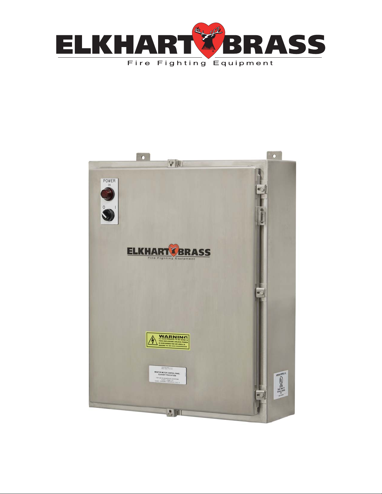
81471067 Electric Monitor Motor Control Panel
For use with Model 8394059 SPIT-FIRE® Monitor
Installation, Operation, and Maintenance Instructions
FOR ATEX APPLICATIONS
WEST BEARDSLEY AVENUE P.O. BOX 1127 ELKHART IN 46515 (574) 295-8330 FAX (574) 293-9914
1302
©
2011 ELKHART BRASS MFG. CO., INC.
98371000 REV. REL
Page 2
PRODUCT SAFETY
Important:
Before installing and operating this equipment, read & study this manual thoroughly. Proper
installation is essential to safe operation. In addition, the following points should be adhered
to in order to ensure the safety of equipment and personnel:
All personnel who may be expected to operate this equipment must be thoroughly trained in its safe and
proper use.
Before flowing water from this device, check that all personnel (fire service and civilian) are clear of the
stream path. Also confirm stream direction will not cause avoidable property damage.
Become thoroughly familiar with the hydraulic characteristics of this equipment, and the pumping
system used to supply it. To produce effective fire streams, operating personnel must be properly
trained.
Whenever possible, this equipment should be operated from a remote location to avoid exposing
personnel to dangerous fire conditions.
Always open and close valves supplying this equipment slowly, so that the piping fills with water
slowly, thus preventing the possible occurrence of water hammer.
After each use, and on a scheduled basis, inspect equipment per instructions in the maintenance section.
Disconnect power prior to servicing controls.
Any modifications to the electrical enclosure will destroy the IP-66 rating and void warranty coverage of
the enclosure and all components within.
All equipment must be installed in accordance with ATEX requirements (EN/IEC 60079-14) as
appropriate and in areas where equipment classification is suitable.
WARNING: Do not attempt to disconnect or work on any electrical equipment in this
system unless power is removed or the area is known to be non-hazardous.
SYSTEM INFORMATION:
SERIAL NUMBER: ______________________________
DETAILS:
__________________________________________________________________________________________
__________________________________________________________________________________________
__________________________________________________________________________________________
2
Page 3

TABLE OF CONTENTS
I. OVERVIEW…………………………………………………………………………………..……......…4
II. INSTALLATION INSTRUCTIONS………………………………………………………..….…..…….5
A. Component Mounting
B. Interconnecting and Wiring Control System
C. MMCP Fuse and Wiring
III. SPECIFICATIONS……………………………………………………………….…...………...........…..7
IV. OPERATING INSTRUCTIONS………………………………………………….…...…..…..............…7
V. MAINTENANCE………………………………………………………………....………...….....…..….7
VI. TROUBLESHOOTING………………………………………………………………..…………........…8
VII. MOUNTING DIMENSIONS……..…….………………………………………………………...…..….9
VIII. ENGINEERING CHANGE REVISIONS EXPLANATIONS………..…………...……………………10
*For our most up-to-date documentation and specifications, please visit our website at www.elkhartbrass.com
3
Page 4

I OVERVIEW
The primary function of the control panel is to operate or control the monitor and nozzle in a controlled
environment or remote location by receiving an electric signal from a Master/Local/Network Control Panel
(OCP), and then sending that signal to the monitor to execute those functions.
Electric Monitor Control Panel Features:
Construction – Stainless Steel enclosure rated for Hazardous Location (Group II, Category 3)
Compliance – II 3 G c (Ex nA nC II T3)
Control Power – On/Off 2-Position selector switch
Pilot Light – Shows panel power on
Internal Power – 24 VDC Power Supply for controls
Control Relays – 24 VDC, 37mA relay inputs for: Monitor directions (UP, DOWN, LEFT, and
RIGHT), Nozzle (STRAIGHT STREAM and FOG), Water and Foam Valves (OPEN and CLOSE).
Water and Foam Valve Options - 24 VDC valve control with 24 VDC valve opened feedback.
Knockouts, Conduit Hubs, and Cable Glands – Supplied by customer.
4
Page 5

II INSTALLATION INSTRUCTIONS
Component Mounting
Monitor Motor Control Panel (MMCP) Installation
1. This enclosure should be located within 100 feet (30.48m) maximum distance to the Monitor
Junction Box.
2. Install the Panel approximately 3-4 feet (.91 to 1.22m) above grade and in the vertical position, on
a rigid structure. Installation is normally at the base of the riser.
3. The enclosure has four (4) mounting pads with .44” (11.18mm) diameter holes. Mounting hole
centers are 18” (457.20mm) horizontal by 31 ¼” (793.75mm) vertical. Please refer to figure 5 on
page 9 for dimensional drawing.
4. Use hubs and glands appropriate for the area classification they will be used in. Also, adhere to
local code requirements for all electrical connections.
Interconnecting and Wiring Control System – Wiring Connection Details Are Inside Panel Door
Main Power to Monitor Motor Control Panel (MMCP)
1. Install conduit from the main power distribution breaker box to Monitor Motor Control Panel.
MMCPs are not provided with conduit hubs unless special ordered.
2. Pull three (3) conductor cables for 1-phase supply (four (4) conductor cables for 3-phase supply),
wire sized to supply a minimum of 500 VA. (For wiring information and sizing see MMCP Fuse
and Wiring Section Figure 4)
Monitor Motor Control Panel (MMCP) to Monitor Junction Box
1. Install conduit between MMCP and Junction Box, located at flanged base of monitor. Junction
boxes are provided with 1 ½” NPT Conduit Hubs.
2. To connect these boxes ten (10) conductors are required with conductor size to be determined by
distance run. (For wiring information and sizing see MMCP Fuse and Wiring Section Figure 4)
Master/Local/Network Control Panel to Monitor Motor Control Panel (MMCP)
1. Install conduit between MMCP and Master/Local/Network Control Box.
2. A minimum of fourteen (14) conductors plus spares are required PER MONITOR
information and sizing see MMCP Fuse and Wiring Section Figure 3)
Monitor Motor Control Panel (MMCP) to optional Water or Foam Valves
1. Install conduit between MMCP and valve.
2. A minimum of six (6) conductors are required PER VALVE
. (For wiring information and sizing
see MMCP Fuse and Wiring Section Figure 3)
. (For wiring
WARNING: Make sure panels are grounded according to area classification and
company policy to assure panel code compliance.
5
Page 6

MMCP Fuse and Wiring
Figure 1: MMCP Fuse and Jumper Diagram
WIRE SIZE FOR CONDUCTORS BETWEEN
MONITOR MOTOR CONTROL PANEL AND
OPERATOR CONTROL PANEL OR VALVES
CONDUCTOR LENGTH WIRE SIZE
UP TO 750 FEET (228.6 m) 18-AWG
750 TO 1500 FEET (457.2 m) 16-AWG
1500 TO 2500 FEET (762 m) 14-AWG
2500 TO 3500 FEET (1066.8 m) 12-AWG
Figure 3: MMCP - OCP Wiring Chart
Figure 2: MMCP Fuse and Jumper Diagram
WIRE SIZE FOR CONDUCTORS BETWEEN
MONITOR MOTOR CONTROL PANEL AND
MONITOR JUNCTION BOX
CONDUCTOR LENGTH WIRE SIZE
UP TO 75 FEET (22.86 m) 18-AWG
75 TO 100 FEET (30.48 m) 16-AWG
100 TO 200 FEET (60.96 m) 14-AWG
200 TO 400 FEET (121.92 m) 12-AWG
Figure 4: MMCP – Monitor Junction Box
Wiring Chart
6
Page 7

III SPECIFICATIONS
General Specs
Input Power 120/240 VAC (50/60Hz.) 1 Phase
480 VAC (50/60 Hz.) 3 Phase
500 VA max. Power
Electrical Load 4 AMPS MAX
Panel Dimensions 24” X 36” (609.60mm X 914.40mm)
Panel Weight Approx. 100 lbs
Operating Temperature Range -10oC to +70oC
ATEX Product Marking
II 3 G c
Ex nA nC II T3
IV OPERATING INSTRUCTIONS
This control panel has one ON/OFF 2-position selector switch. Move it to the ON position so the pilot light
illuminates, showing the panel is now powered up, and ready for associated monitor operation.
V MAINTENANCE
Power converts to 24
VDC in control panel
Monthly Inspection and Maintenance
1. Check the indicator light and replace bulb if it’s not operable.
2. Confirm that all terminal blocks and connections are properly taut to 4.5 – 7.1 in-lbs. (0.508 – 0.802
Nm).
3. Check for proper operation of the system overall, if there are problems with the system please refer to
the Troubleshooting section for help.
7
Page 8

VI TROUBLESHOOTING
A. If Panel will not power up:
1. Check the incoming supply power, and if it’s the proper power requirement for the system.
2. Check to make sure the transformer is wired correctly.
3. Check fuses in panel to confirm they are good. If fuses are blown, replace them with same or
equivalent fuse.
a. Check for causes in the interconnect wiring and connections.
b. Verify that the OCP/NCP is not trying to activate the monitor motor functions
c. If nothing is found consult with your Elkhart Brass representative.
4. Check panel power switch to make sure it is in the “Power On” position.
5. Check power supply to confirm there is 120 VAC running to it.
B. If Pilot Light is not on when panel has power:
1. Check the light bulb, and replace if it is burnt out.
C. Function not working correctly:
1. Check to see if there is a loose connection at the terminal blocks or contact blocks. Make sure all
screw terminations are properly tightened to 4.5 – 7.1 in-lbs (0.508 – 0.802 Nm)
2. Check relay for actuation. If bad, replace relay with new working relay.
D. Water or Foam valve will open but will not close when operated.
1. Verify that jumpers between terminals (10 and 14) or (15 and 19) are removed.
Please refer to our website at www.elkhartbrass.com for any further information. Any problems that
cannot be fixed/solved should be taken to your Elkhart Brass Representative.
WARNING: Do not attempt to disconnect or work on any electrical equipment in this
system unless power is removed or the area is known to be non-hazardous.
8
Page 9

VII MOUNTING DIMENSIONS
Figure 5: MMCP Mounting Dimensions
9
Page 10

VIII ENGINEERING CHANGE REVISION EXPLANATIONS
10
Page 11

NOTES:_________________________________________________________________________________
________________________________________________________________________________________
________________________________________________________________________________________
________________________________________________________________________________________
________________________________________________________________________________________
________________________________________________________________________________________
________________________________________________________________________________________
________________________________________________________________________________________
________________________________________________________________________________________
________________________________________________________________________________________
________________________________________________________________________________________
________________________________________________________________________________________
________________________________________________________________________________________
________________________________________________________________________________________
________________________________________________________________________________________
________________________________________________________________________________________
________________________________________________________________________________________
________________________________________________________________________________________
________________________________________________________________________________________
________________________________________________________________________________________
________________________________________________________________________________________
________________________________________________________________________________________
________________________________________________________________________________________
________________________________________________________________________________________
________________________________________________________________________________________
________________________________________________________________________________________
________________________________________________________________________________________
________________________________________________________________________________________
________________________________________________________________________________________
________________________________________________________________________________________
________________________________________________________________________________________
________________________________________________________________________________________
________________________________________________________________________________________
________________________________________________________________________________________
________________________________________________________________________________________
________________________________________________________________________________________
________________________________________________________________________________________
________________________________________________________________________________________
________________________________________________________________________________________
________________________________________________________________________________________
________________________________________________________________________________________
________________________________________________________________________________________
________________________________________________________________________________________
________________________________________________________________________________________
________________________________________________________________________________________
________________________________________________________________________________________
________________________________________________________________________________________
________________________________________________________________________________
11
 Loading...