

Page 1
7161 EXM UHP
Installation, Operating, & Maintenance Instructions
98391000 REV. REL
1302 WEST BEARDSLEY AVENUE P.O. BOX 1127 ELKHART IN 46515 (574) 295-8330 FAX (574) 293-9914
©
2012 ELKHART BRASS MFG. CO., INC.
Page 2

EXM UHP – Table of Contents
Table of Contents –
Product Safety Information……………………………………………………….…………..3
System Components……………………………………………………………..…………....4
Installation Instructions…………………………………………………………………..…...6
Installation Overview………………………………………………..…………....…..6
Installation Step 1 – Mount and Wire All System Components…………...................7
Installation Step 2 – Configure the EXM System…………………………..……….10
Installation Step 3 – Calibrate the EXM System…………………………………….14
Installation Step 4 – Check Installation…………………………..……………..…...15
Operating Instructions……………………………………………………………...…..……16
A. Button / Joystick Operation
B. Setup Mode
C. Re-Calibrating Rotation
D. Travel Limits
E. Keep-Out Zones
F. Stow Position
Maintenance Instructions……………….…………………………………..………..……....23
A. Preventive Maintenance B. Understanding System LEDs
System Specifications…………………..…………………………………………....……....24
Monitor Callout Drawing……………………………………………..……………………..25
Component Mounting Templates………………………………………....…………………27
G. Motor Speed
H. Clear All Function
I. Oscillation
J. Auxiliary
K. Write Diagnostic File
L. Firmware Update
To view the most current parts list, drawings, or demonstrations of common EXM commands,
please visit www.elkhartbrass.com.
2
Page 3
EXM UHP– Product Safety Information
Product Safety Information -
1. All personnel who may be expected to use this equipment must be thoroughly trained in its safe and
proper use.
2. Before flowing water from this device, check that all personnel (fire service and civilian) are out of the
stream path. Also, check to make sure stream direction will not cause avoidable property damage.
3. Become thoroughly familiar with the hydraulic characteristics of this equipment, and the pumping
system used to supply it. To produce effective fire streams, operating personnel must be properly
trained.
4. Whenever possible, this equipment should be operated from a remote location. Do not needlessly
expose personnel to dangerous fire conditions.
5. Open water valves supplying this equipment slowly so that piping fills slowly, thus preventing possible
water hammer occurrence.
6. After each use, and on a scheduled basis, inspect equipment per instructions in section VII.
7. Any modifications to the electrical enclosures will destroy the NEMA 4 rating and void warranty
coverage of the enclosure and all components within.
Important: Before installing and operating provided equipment, read this manual
thoroughly. Proper installation is essential to safe equipment operation.
SYSTEM INFORMATION:
MONITOR SERIAL NUMBER: ______________________________
MONITOR ACCESSORIES (NOZZLE GALLONAGE AND TYPE, ETC.):
__________________________________________________________________________________________
__________________________________________________________________________________________
__________________________________________________________________________________________
__________________________________________________________________________________________
__________________________________________________________________________________________
__________________________________________________________________________________________
3
Page 4
EXM UHP– System Components
System Components -
In this section, the reader will be introduced to the various
The reader’s specific
A. EXM Monitor – 7161
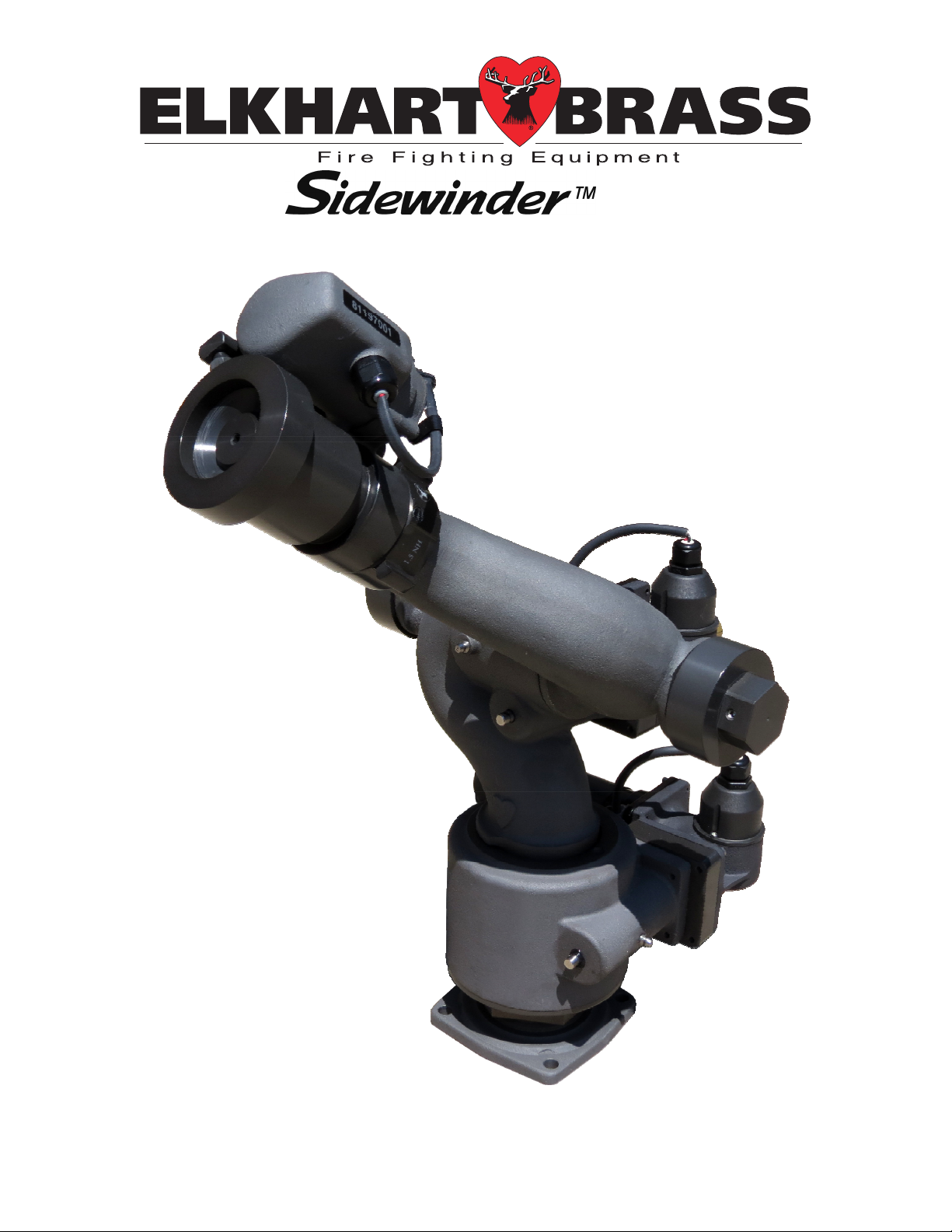
The Sidewinder EXM monitor is specially designed for severe duty cycles.
Unique waterway swivel joints utilize stainless steel thrust rods and needle
roller thrust bearings for unprecedented durability in mining, construction,
and wild land firefighting applications. The monitor can be controlled by
hardwired input devices via CAN bus. The monitor may be powered with
12 or 24 Volts.
High power, permanent magnet variable speed DC gear motors that drive
the left-right and up-down monitor motions are NEMA 4 rated for use in
harsh environments. The Sidewinder EXM monitor has a flow efficient 21/4” vaned waterway to minimize turbulence and provide superior nozzle
streams. The water supply connection in the monitor base is a 2-1/2” female
national pipe thread, and the discharge nozzle connection has a 1-1/2”
national hose male thread.
EXM system may not include all components shown in this section.
EXM system components.
Figure 1: 00007161
EXM UHP
Caution: All EXM monitor motors are 12VDC. If using a non-
EXM nozzle on the EXM monitor, another 12VDC nozzle should
be used, or nozzle control may not function properly.
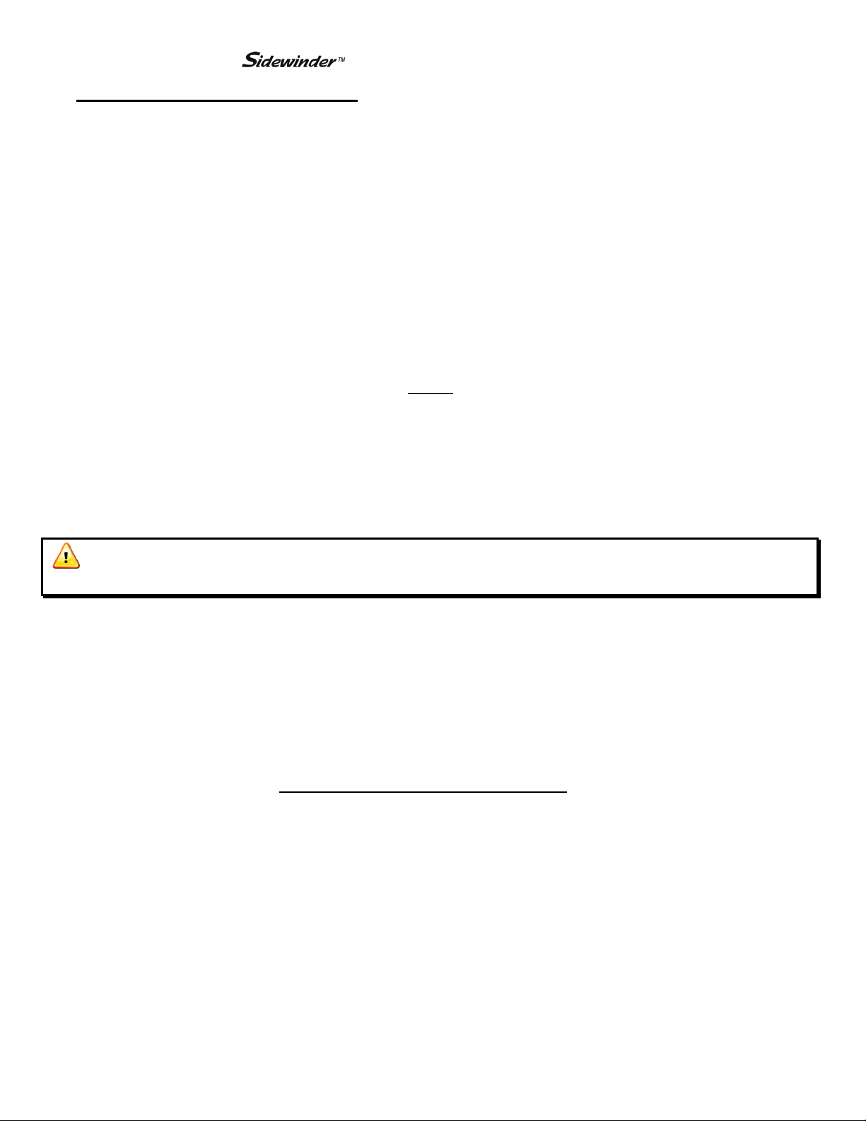
B. Joystick Controller - 7030
The Joystick Controller must be used in conjunction with the 7070 OEM
Interface Module. The Joystick Controller can be mounted inside the
apparatus cab to control all monitor functions, including oscillation. The
monitor direction (both vertical and horizontal movement) is changed by
moving the joystick in the desired direction of travel. The up-down and
left-right motions can be operated simultaneously with pressure sensitive
speed, moving the monitor faster or slower depending on how far the
joystick is pushed and pulled. Nozzle pattern can be changed using the
thumb wheel on the top of the joystick. Oscillation is programmed by using
the joystick in conjunction with the oscillate button.
Caution: Any modification of the Joystick enclosure will destroy the NEMA 4 rating to
that piece of equipment and will void the warranty coverage.
Figure 2: 00007030
Joystick Controller
4
Page 5
EXM UHP– System Components
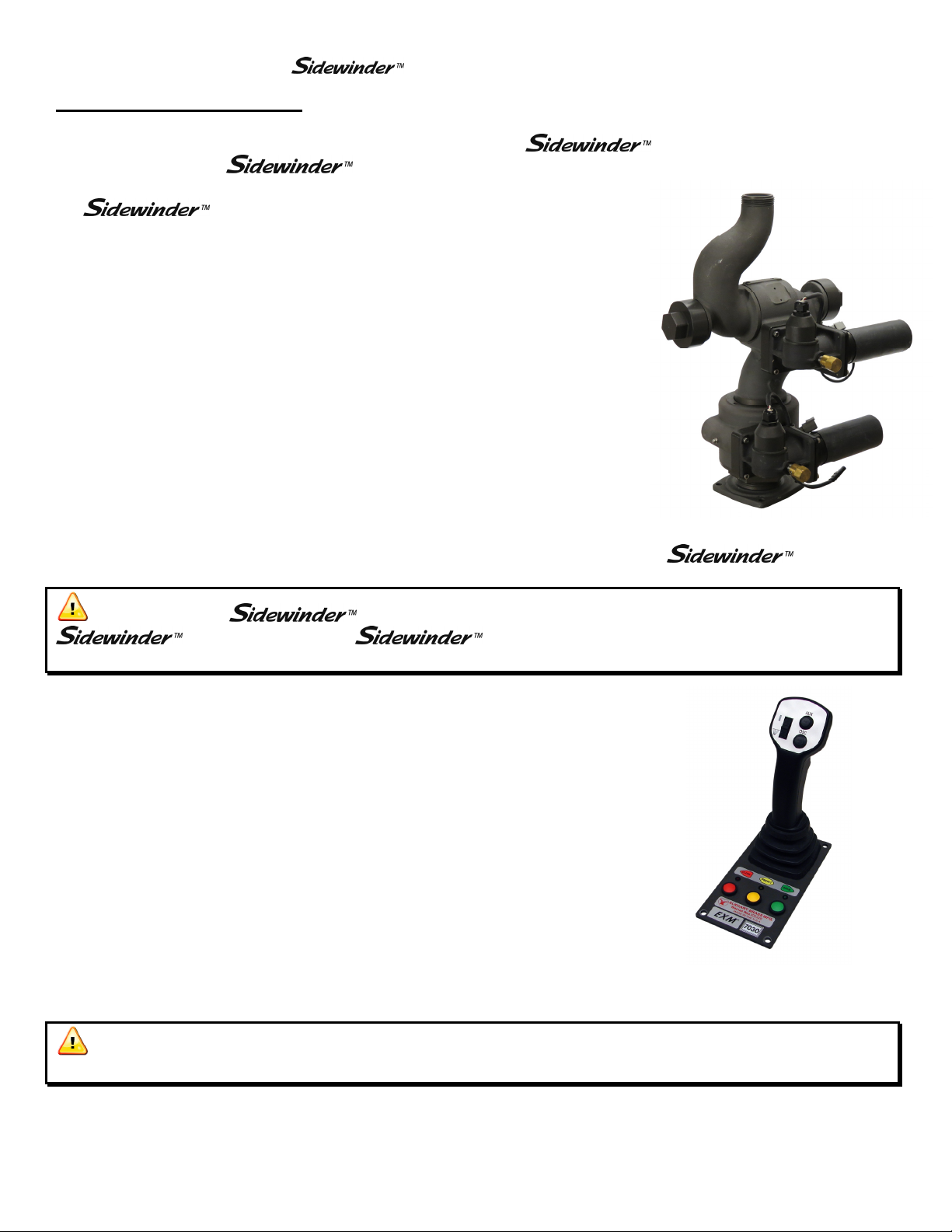
C. OEM Interface Module - 7070
The OEM Interface Module is used in conjunction with either the Elkhart
Brass or customer supplied joystick, or OEM installed switches. The OEM
Interface Module may be configured to handle switching power or ground.
The Interface Module provides the option of mounting a joystick or switches
in the apparatus cab to control all monitor functions, including oscillation.
The OEM Interface Module may be powered with 12 or 24 Volts.
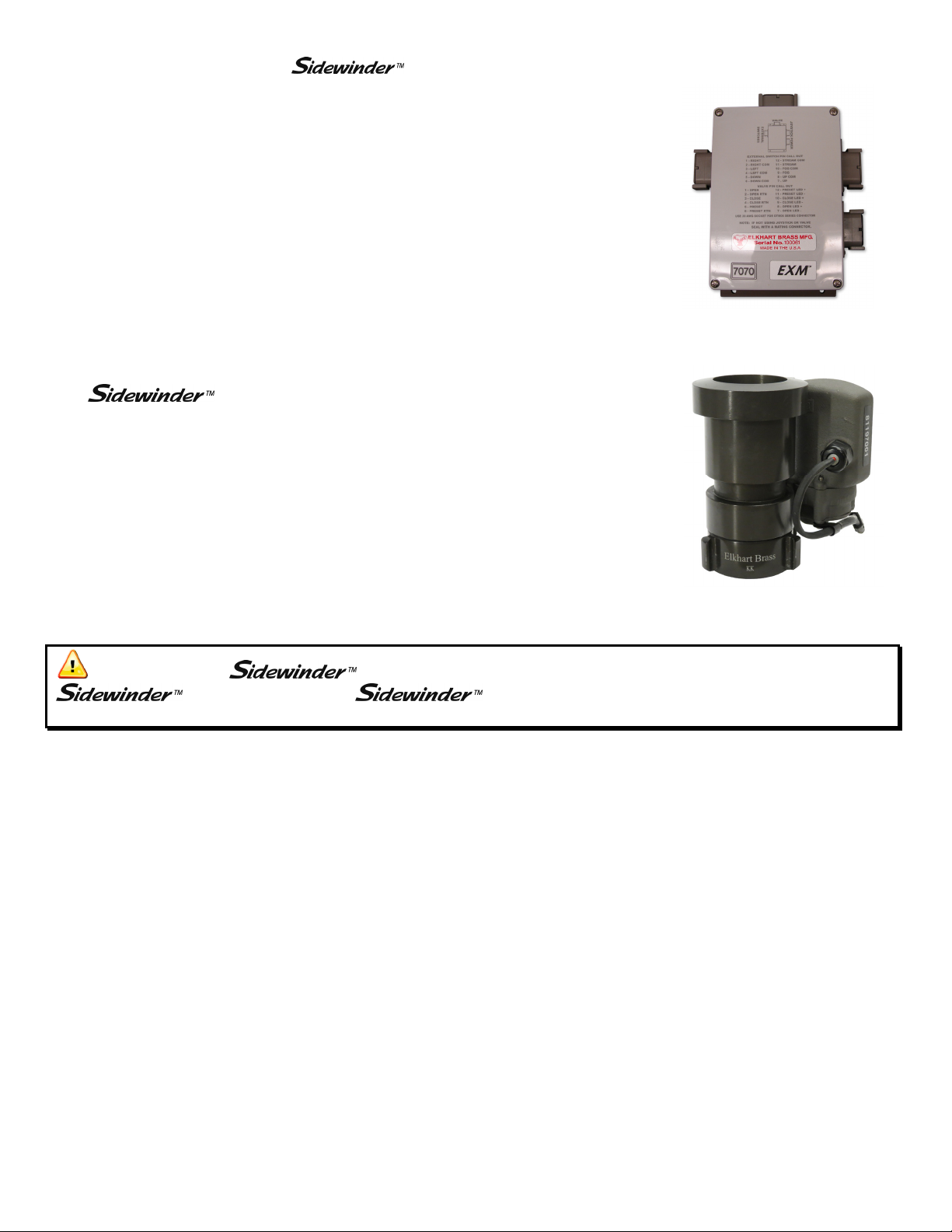
D. EXM Nozzles –
5000-14E UHP
The nozzle has a fixed flow rate with an electrically actuated stream
pattern adjustment
5000-14E UHP; 100 GPM.
Figure 4: Sidewinder EXM UHP
Figure 3: 00007070
OEM Interface Module
Nozzle
Caution: All EXM monitor motors are 12VDC. If using a non-
EXM nozzle on the EXM monitor, another 12VDC nozzle should
be used, or nozzle control may not function properly.
5
Page 6
EXM UHP– Installation Instructions
(Installation Overview)
Installation Instructions -
In this section, the reader will be guided through the steps listed in the installation overview below. The
installation of the reader’s specific EXM system may not require all of the instructions
included in this manual.
Please keep in mind the following wiring recommendations when mounting and wiring the
Recommended electrical requirements for EXM monitor:
Installation Overview:
Step 1 – Mount and Wire All System Components (Pages 7)
Step 2 – Configure the EXM System (Pages 10)
Step 3 – Calibrate the EXM System (Pages 14)
Step 4 – Check Installation (Page 15)
EXM system components.
Power and Ground wire gauge and length: Distance (Ft) Wire Gauge (AWG)
100 - 150 8
50 < 100 10
25 < 50 14
< 25 16
Power and Ground wire type: Cross Link or equivalent (Must meet or exceed NFPA 1901 Section 13)
Maximum monitor amperage draw: 20 AMPS
CAN wire gauge and length: Any length – 18-22 AWG
CAN wire type and shielding: Twisted shielded pair - 105°C 150V (Belden 9841 series or equivalent)
o Shield Drain: Connect shield/drain to pin C of J1939 connector
Recommended electrical requirements for the 7000 series input devices:
Power and Ground wire gauge and length: Any length - 22 AWG 105°C 150V
Maximum input controller amperage draw: 500mA
CAN wire gauge and length: Any length – 18-22 AWG
CAN wire type and shielding: Twisted shielded pair - 105°C 150V (Belden 9841 series or equivalent)
o Shield Drain: Connect shield/drain to pin C of J1939 connector
Docking station wire gauge type: 22 AWG cross link or equivalent
6
Page 7
EXM UHP– Installation Instructions
(Step 1 – Mount and Wire All System Components)
Installation Step 1: Mount and Wire All System Components
Installation instructions have been included for all EXM components. The reader is advised to
skip all instructions that pertain to components not included in his or her own EXM system.
A. EXM Monitor –
Before mounting the EXM
monitor, ensure that space allows for
monitor to be rotated and calibrated.
Disconnect all electrical connections.
Thread monitor onto male 2.5” NPT thread
using Loctite 592 or equivalent thread
sealant. Tighten using a strap wrench on the
hex portion of the monitor base.
If the monitor will use a CAN string to
communicate with other EXM components,
connect plug 2 leads to the appropriate CAN
string leads.
o If the CAN leads will not be used,
replace wires with appropriate plugs.
Supply power to the monitor by connecting
the red and black leads from the 6 pin
connector to an appropriate power source.
Install a 20 Amp fuse into the positive
power lead for a 12V system (10 Amp for
24V system) to protect the monitor electrical
components.
Refer to the respective plug figures for
information on the plugs’ pins.
Caution: Do not use motors or discharge as
leverage to tighten monitor.
7
Page 8
EXM UHP– Installation Instructions
(Step 1 – Mount and Wire All System Components)
B. Joystick Controller and OEM Interface Module –
Using the template shown on page 28, drill
all holes shown onto the surface intended for
mounting the Joystick Controller.
Mount the Joystick Controller using the
supplied 10-24 x ½” screws using blue
Loctite 242 or equivalent.
Using the template shown on page 27, drill
all 4 of the 7/32” holes shown.
Mount the OEM Interface Module with four
10-24 x ½” screws using blue Loctite 242 or
equivalent.
Connect the plug coming from the Joystick
Controller stick to plug 2 on the OEM
Interface Module. (See picture to the right)
If the Joystick/OEM will use CAN
communication, connect the green, black,
and blue leads coming from plug 1 to the
appropriate CAN line. (See picture below)
Supply power to the OEM Interface Module
and Joystick by connecting the red and black
leads coming from plug 1 to an appropriate
power source. (See picture on previous
page)
Install a 1 Amp fuse into the positive power
lead of the OEM Interface Module for a 12V
system (1/2 Amp for 24V system).
Refer to the respective plug figures on the
previous page for information on the plugs’
pins.
For information regarding external switches
and customer supplied joysticks, refer to the
pin information found on the Module cover.
If there are any unused OEM Interface
Module connections, plug the connections
with appropriate Deustch connectors and
plugs.
1
Valve Plug
OEM Interface Module Plug Information
Joystick Plug Information
2
2
1
8
Page 9
(Step 1 – Mount and Wire All System Components)
C. Nozzles –
Ensure there is a gasket inside the nozzle
swivel.
Hand tighten the nozzle onto the monitor
discharge.
Loosen the swivel to reposition the nozzle
with the locking lever on the underside of
the nozzle as shown.
O-ring & Gasket Location
EXM UHP– Installation Instructions
Tighten the nozzle swivel with a spanner wrench.
Supply power to the nozzle by connecting the
monitor and nozzle two-way connectors.
Two-Way Connector
9
Page 10

EXM UHP– Installation Instructions
(Step 2 – Configure the System)
Installation Step 2: Configure the EXM System
Obtaining the EXM Configuration Tool –
To obtain the latest EXM Configuration Tool go to www.elkhartbrass.com. Starting from the homepage, go to
the Downloads drop down menu and select Product Aids. On the Product Aids page scroll down the page to the
Monitors section and find the EXM Configuration Tool. Download and install this program to your computer.
EXM System Groups –
When configuring a custom EXM system, only one group may be configured at a time. A group is one
complete EXM system containing at least 1 monitor and 1 input controller. A group may contain multiple input
controllers, 1 Valve, and 1 Position Indicator Display. If installing multiple EXM groups onto a single CAN
line, the groups must be numbered and configured with their respective group number.
EXM Valves –
If two EXM groups both containing valves are to be installed onto the same CAN line, only the valve being
configured should be connected to the CAN line. Any other valves, not in the EXM group being configured,
must be disconnected from the CAN line. When the second EXM group is to be configured, disconnect the
valve in the first group and connect the valve in the second.
Configuration Steps –
1 2
After installation, run the Configuration
program by double-clicking on the
desktop icon shown to the left. You
will see the splash screen below when
the program is loading.
When the Configuration Tool starts you will see the
screen shown above.
The settings chosen during this process will act as the
default settings of the monitor. These settings are
what the monitor will convert back to when the Clear
All function is entered with one of the input
controllers.
(Continue on to Steps 3 and 4 on the following page)
10
Page 11

EXM UHP– Installation Instructions
(Step 2 – Configure the System)
3 4
Under the Monitor Settings tab, enter the serial
number of the monitor being configured. This
number can be found on the monitor control box.
5 6
When using CAN communication within the EXM
system, 2 and only 2 components must be terminated
to ensure proper communication along the CAN line. .
If there have been no physical termination points
installed within your system, two termination points
must be selected during configuration.
Here is the first opportunity to terminate any of the
CAN operated EXM components in your system.
To maximize the efficiency of communication in your
CAN network, the two components to be terminated
should be at the extreme ends of your CAN line.
In the drop down menu, the monitor type can be
selected.
At the bottom of the Monitor Settings tab, default
settings regarding the Speed and Range of rotation of
your EXM monitor can be set.
Motor speeds can be changed after system
configuration is complete, if desired.
Travel amounts may be decreased after system
configuration but may not be increased further than
what is set as default during system configuration.
11
Page 12

EXM UHP– Installation Instructions
(Step 2 – Configure the System)
7 8
On the Input Controllers tab, enter the serial numbers
for all input controllers in your EXM system.
Please note that the top line is designated for the
Primary input controller. The controller designated as
the Primary will override any other commands given
to the system from Secondary controllers.
Also, please note that the Serial Number entered for
the Joystick/OEM is actually the number listed on the
OEM Interface Module used with that Joystick.
9
In the drop down menu, the input controller type for
each controller must be selected.
Also, choose the type of communication that the
controller will use; CAN line.
The Input Controls tab is also the second opportunity
to terminate components within your EXM system.
Please refer back to configuration step 5 for an
explanation of CAN communication and terminating
system components.
12
Page 13

EXM UHP– Installation Instructions
(Step 2 – Configure the System)
10
Go to the Save Settings tab to save the configuration file to a
USB flash drive. Simply click ‘Browse’ and select the drive
location. Click the ‘Save to USB’ button and a popup
message will appear confirming that the configuration file
has been saved. To ensure that the configuration file will
properly configure the EXM system, use a blank USB.
The checkboxes on the left side of this tab allow you to
choose whether you will configure you system’s Monitor,
Input Controllers and Valve, or Position Display. If this is
your first time configuring your system, you will likely need
to check all boxes.
The box labeled Group Number allows you to change the
EXM group being configured. This number changes
automatically based on monitor type and only needs to be
changed if multiple monitors of the same type are being used
on the same CAN line (i.e. Sidewinder with Sidewinder).
Click the Exit tab to close the program when finished.
After the configuration file for your system has been successfully saved to a USB flash drive, ensure that all CAN
components are connected and power up all components within the EXM system. (To power on a Handheld
Controller that is hibernating, press and release the AUX button)
13
Page 14

EXM UHP– Installation Instructions
(Calibrate the EXM System)
Installation Step 3: Calibrate the EXM System
After successfully configuring the system, the system must be calibrated. Calibrating the EXM system’s
horizontal is a necessary step for EXM systems of all types.
To view a demonstration of system calibration and entering setup commands go to www.elkhartbrass.com to
download the appropriate EXM System Instructional Video.
A. Setup Mode
Before the EXM system can be calibrated, the system must be put into Setup Mode. To bring the system into
Setup Mode press and hold the FOG and STREAM buttons simultaneously for 2 seconds. (On the joystick use
the PRESET and AUX buttons)
When the system has successfully been brought into Setup Mode, the blue status LED on the monitor and
the yellow status LED on the input controller (top right corner) will light. (There is no status LED on the
joystick, instead all valve button LEDs will flash once)
Once in Setup Mode a user can set travel limits, travel keep out zones, and stow position, as well as
change motor speeds, etc.
When in Setup Mode the RIGHT, LEFT, UP, and DOWN buttons function normally, but valve OPEN,
CLOSE, and PRESET do not control the valve. Instead, they are used for entering setup commands.
To leave Setup Mode simply press and release the FOG and STREAM buttons simultaneously one time.
Changes made will not take effect until after exiting Setup Mode. Setup Mode will automatically be
exited after five minutes of no user inputs.
Caution: There are no vertical or horizontal travel limits when in Setup Mode. Move the
monitor with caution while in this mode. If monitor is obstructed by an object or by itself, the
motors may over current and need to be moved manually out of the interfering object’s way.
B. Calibrating Horizontal and Vertical Rotation
Calibrating the EXM system’s horizontal and vertical rotation is a necessary step for EXM systems of all types.
The calibration points serve as a starting point for all other motion limits and commands entered to the EXM
system. If not properly calibrated, the system may not operate correctly.
Calibrating Horizontal Rotation - This calibration process will establish the zero (0˚) horizontal position
and allow rotation half to the left and half to the right of the total rotation range specified during system
configuration.
o Using RIGHT, LEFT, UP, and DOWN buttons, position the monitor such that it is aimed at the
center forward position (i.e. the 0˚ horizontal position).
14
Page 15

EXM UHP– Installation Instructions
(Calibrate the EXM System)
o Press and hold PRESET and then press either the LEFT or RIGHT button. (On the joystick, hold
PRESET and move the stick to the right or left and release)
o The status LED on the monitor should blink then turn solid.
o Release the PRESET and either the LEFT or RIGHT button. The horizontal axis is now calibrated.
Calibrating Vertical Rotation - The Vertical zero (0˚) position is factory set, however you may still set a
new vertical zero point. This calibration will establish the highest vertical travel point of the monitor and
allow rotation in the downward direction the total range specified during system calibration. This differs
from the horizontal rotation calibration where the zero point is in the middle of the rotation range.
o Using RIGHT, LEFT, UP, and DOWN buttons, position the monitor such that it is aimed directly
vertical or at the uppermost limit of travel specified during system configuration.
o Press and hold PRESET and then press the UP button. (On the joystick, hold PRESET and move the
stick up and release)
o The status LED on the monitor should blink then turn solid.
o Release the PRESET and UP buttons. The vertical axis is now calibrated.
o Exit Setup Mode and check the monitor’s rotation limits. The monitor should not hit itself or other
objects. Recalibrate the EXM system if needed.
Caution: If the vertical zero point is set too far forward, the monitor may be allowed to
crash into itself at the lower points of vertical travel. Be careful not to move the monitor into
obstructions or itself as this will cause the monitor motors to over current. The monitor may
need to be moved in reverse, manually, if this occurs.
Installation Step 4: Check Installation
After mounting, wiring, configuring, and calibrating the
installation of the entire EXM system.
Ensure that all components have been mounted securely and have had the correct fuses installed within
their wiring leads.
Ensure that all components have been configured and that all components are functioning.
Ensure that the
Ensure that all components are performing normally.
o For a list of operating functions that the EXM system should be capable of
performing, go to the operating instructions section on page 16.
EXM system has been calibrated correctly for its specific installation.
EXM system, check the
15
Page 16

EXM UHP– Operating Instructions
Operating Instructions -
In this section the reader will be guided through basic operation of the EXM system. A short explanation
of the various buttons and Joystick operation will be given. This section will also guide the user through
entering system commands such as rotation limits, keep-out zones, and stow position.
To view a demonstration of some operating commands go to www.elkhartbrass.com to download the
appropriate EXM System Instructional Videos.
A. Button / Joystick Operation
STREAM – Moves the nozzle in order to
flow a straight stream of water
(Roll thumbwheel forward on the Joystick)
FOG – Moves the nozzle in order to flow a
fine mist of water
(Roll thumbwheel backward on the Joystick)
UP – Moves the monitor in the upward
direction
(Pull the Joystick handle back)
DOWN – moves the monitor in the
downward direction
(Push the Joystick forward)
RIGHT – moves the monitor to the right
(Pull the Joystick to the right)
LEFT – moves the monitor to the left
(Pull the Joystick to the left)
B. Setup Mode
Before some system commands can be entered into the EXM system, the system must be put into Setup Mode.
To bring the system into Setup Mode press and hold the FOG and STREAM buttons simultaneously for 2
seconds. (On the joystick use the PRESET and AUX buttons)
Please refer back to Step 3 in the Installation Instructions section for directions of how to enter and exit
Setup Mode.
OSC (OSCILLATE) – Used to set automatic
motion of the monitor
(See step I, Oscillation for directions)
AUX (AUXILIARY) – Used for various
operations including light operation, etc.
(See step L, Auxiliary for directions)
CLOSE – Closes the electric valve within the
EXM system
(See step K, Valve Operation for directions)
PRESET – Opens the electric valve to a
specified position set by the user
(See step K, Valve Operation for directions)
OPEN – Opens the electric valve within the
EXM system
(See step K, Valve Operation for directions)
TRIGGER (Joystick) – Opens valve when
pulled. When released, valve will close.
Caution: There are no travel limits when in Setup Mode. Move the monitor with caution
while in this mode. Be careful not to move the monitor into obstructions or itself as this will
cause the monitor motors to over current. The monitor may need to be moved in reverse,
manually, if this occurs.
16
Page 17

EXM UHP– Operating Instructions
C. Re-calibrating Horizontal and Vertical Rotation
Calibrating the EXM system’s horizontal and vertical rotation is a necessary step for EXM systems of all types.
The calibration points serve as a starting point for all other motion limits and commands entered to the EXM
system. If not properly calibrated, the system may not operate correctly.
The EXM system should be calibrated from when installation of the EXM system occurred, but if it is desired
that the monitor’s rotation be re-calibrated it is possible to do so. Please refer back to Step 3 in the Installation
Instructions section for directions of how to calibrate, or re-calibrate your EXM system.
D. Travel Limits
Travel limits are used when it is desired to restrict the motion of the monitor to a smaller, more specific range
than the one set as default during system configuration. Travel limits can be used to aid in avoiding objects that
may interfere with the motions of the monitor.
It is important to note that travel range can not be increased further than that range which was set as system
default during system configuration. If a larger travel range is desired, this must be changed by reconfiguring
the system with the EXM Configuration Tool.
Horizontal Travel Limits
o Put the EXM system into the Setup Mode (reference Part B of the Operating Instructions section)
o Move the monitor to the intended point of left-most (or right-most) travel
o The horizontal travel limit should be set within the total allowed factory set travel or total travel
specified during configuration of the system. If a travel limit is set outside the intended operating
area, operation of the monitor may be unpredictable.
o To set the left-most travel point, press and release the CLOSE button
(To set the right-most travel point press and release the OPEN button)
o When the EXM system is brought out of Setup Mode, horizontal travel limits will be set
Vertical Travel Limits
o Put the EXM system into the Setup Mode (reference Part B of the Operating Instructions section)
o Move the monitor to the intended point of highest (or lowest) travel
o The vertical travel limit should be set within the total allowed factory set travel or total travel
specified during configuration of the system. If a travel limit is set outside the intended operating
area, operation of the monitor may be unpredictable.
o To set the highest travel point, hold the STREAM button and press the UP button
(to set the lowest travel point hold the STREAM button and press the DOWN button)
o When the EXM system is brought out of Setup Mode, vertical travel limits will be set
17
Page 18

EXM UHP– Operating Instructions
E. Keep-Out Zones
Keep-Out Zones are used when it is desired to restrict the motion of the monitor to a smaller more specific
range than that set during system calibration. Keep-Out Zones are different from travel limits in that they do
not restrict motion completely in any one direction. Keep-Out Zones can be set to allow the monitor to move
above a certain zone or beside the zone to either the left or right.
Lower-Right Keep-Out Zone - The Right Keep-Out Zone will prevent the monitor from moving down
and to the right into a specified zone (reference figure 1 on the following page)
o Put the EXM system into Setup Mode (reference Part B of the Operating Instructions section)
o Move the monitor to the upper left corner of the keep out zone
o The Keep-Out Zone should be set within the previously set monitor calibration points. If a Keep-
Out Zone is set outside the intended operating area, operation of the monitor may be unpredictable.
o Press the PRESET and OPEN buttons at the same time
o When the EXM system is taken out of Setup Mode, the monitor will be prevented from moving
below and to the right of this point
Lower-Left Keep-Out Zone - The Left Keep-Out Zone will prevent the monitor from moving down and
to the left into a specified zone (reference figure 1 below)
o Put the EXM system into Setup Mode (reference Part B of the Operating Instructions section)
o Move the monitor to the top right corner of the keep out zone
o The Keep-Out Zone should be set within the previously set monitor calibration points. If a Keep-
Out Zone is set outside the intended operating area, operation of the monitor may be unpredictable.
o Press the PRESET and CLOSE buttons at the same time
o When the EXM system is taken out of Setup Mode, the monitor will be prevented from moving
below and to the left of this point
Figure 1 – Keep-Out Zones
18
Page 19

EXM UHP– Operating Instructions
F. Stow Position
The Stow Position is a preset position that can be used to bring the monitor into a position suitable for when the
system is powered off. A stow position must be within the allowed travel area defined by any travel limits or
keep out zones.
Put the EXM system into Setup Mode (reference Part B of the Operating Instructions section)
Move the monitor to the desired position
The Stow Position should be within the previously set monitor rotation limits. If Stow Position is set
outside the intended operating area, operation of the Stow command may be unpredictable.
Press the FOG and OSCILLATE buttons at the same time (rotate thumbwheel down for FOG on Joystick)
This position will be the Stow Position when the system is brought out of Setup Mode
Simply press and hold the FOG and OSCILLATE buttons for three seconds to put the monitor into the
Stow Position while outside of Setup Mode (rotate thumbwheel down for FOG on Joystick)
Warning: Water should not be flowing while using the Stow Position command.
G. Motor Speed
The speed of both the horizontal and vertical motors can be changed from something different than that set
during configuration of the EXM system. The monitor’s horizontal and vertical motors can be set to either Fast
or Slow in one of four combinations.
Put the EXM system into the Setup Mode (reference Part B of the Operating Instructions section)
Press the OSCILLATE button to cycle through the various motor speed combinations
o The horizontal, vertical, and nozzle LED’s on the monitor are used to show which motor speed
combination the monitor will be set at after Setup Mode is exited
o All Yellow LED’s “OFF” places both motors in fast mode
All Yellow LED’s “ON” places both motors in slow mode
One Yellow LED only “ON” indicates horizontal motor fast and vertical motor slow mode
Two Yellow LED’s only “ON” indicates horizontal motor slow and vertical motor fast mode
When the system is brought out of Setup Mode, the motor speeds will be changed to the combination
selected
19
Page 20

EXM UHP– Operating Instructions
H. Clear All Function
The Clear All Function allows the user to remove any Travel Limits, Keep-Out Zones, or Stow Positions set
while in Setup Mode. When the Clear All Function is used, it will remove all of the previously listed
operations. The Clear All Function will not affect calibration points, Motor Speed, or Preset valve positions.
Put the EXM system into Setup Mode (reference Part B of the Operating Instructions section)
Press the OPEN and CLOSE buttons simultaneously
All set Travel Limits, Keep-Out Zones, and Stow Positions will be removed from the system
I. Oscillation
The oscillation function is used to move the monitor back and forth inside a boxed area or straight horizontal or
vertical line specified by the user.
Move the monitor to one corner of the intended boxed area (For a straight horizontal or vertical line,
move monitor to the first line endpoint.)
Press the OSCILLATE button
Move the monitor to the opposite corner of the intended boxed area (For a straight horizontal or vertical
line, move monitor to the opposite endpoint of the line.)
Press the OSCILALTE button a second time
The monitor should begin moving up and down, and left and right within the boxed area. (If setting a
horizontal or vertical line, monitor should begin oscillating horizontally or vertically only.)
If there is no monitor movement for 30 seconds while setting up the oscillation limits, the monitor will
automatically exit oscillate setup
Pressing UP, DOWN, LEFT, RIGHT, or OSCILLATE will stop oscillation of a boxed area (Pressing
LEFT, RIGHT, or OSCILLATE will stop horizontal oscillation while pressing UP, DOWN, or
OSCILLATE will stop vertical oscillation.
o All other functions can be operated without stopping oscillation.
J. Auxiliary
Turn on/off optional light 1 – Press AUX and FOG simultaneously
Turn on/off optional light 2 – Press AUX and STREAM simultaneously
20
Page 21

EXM UHP– Operating Instructions
K. Write Diagnostic File
Remove the USB cover from any input controller.
Install a blank USB flash drive into the USB port of the desired input controller, and the controller will
automatically enter Programming Mode (If Update Mode does not initiate, hold AUX and OSCILLATE
for 2 seconds)
o The yellow status LED on controller will begin to blink once per second
o If using Joystick, all valve LEDs will flash once to indicate that you are in Programming Mode
Press and release the OPEN button
A diagnostic file called EBDIAG.CSV is written to the USB flash drive
Remove the USB from the input controller to leave Programming Mode
Contact Elkhart Brass to make arrangements to send the EBDIAG.CSV file for review.
L. Update Firmware
Before updating firmware ensure that all components intended for the update are powered up and
connected to the chosen input controller through either the CAN string.
Remove the USB cover from any input controller.
o Although any input controller may be used for updating firmware, it is suggested that a controller
connected via the CAN string is used, if available.
Install the USB flash drive with the newest firmware version into the USB port of the desired input
controller, and the controller will automatically enter Programming Mode (If Update Mode does not
initiate, hold AUX and OSCILLATE for 2 seconds)
o The yellow status LED on controller will begin to blink at once per second
o If using Joystick, all valve LEDs will flash once to indicate that you are in Update Mode
Press and release the PRESET button
The input controller will read the hex file on the flash drive and install it as long as the copied firmware is
newer than the existing firmware.
o This process will likely take up to ten minutes to complete.
o This action will also update all input controllers on the CAN bus (primary and secondary)
21
Page 22

EXM UHP– Operating Instructions
o Once all of the input controllers are updated and there were no errors while upgrading; then the
preset LED will blink once every three (3) seconds.
o If the primary input controller does not recognize it as newer firmware, then no update will take
place and the preset LED will flash twice every three (3) seconds.
o If the update did not perform correctly, the preset LED will blink three times every three (3)
seconds. If the update did not perform correctly please call Elkhart Brass at (800) 346-0250.
Remove the USB from the input controller to leave Programming Mode
22
Page 23

EXM UHP– Monitor Callout Drawing
Maintenance Instructions -
In this section, the reader will be instructed on how to properly care for their EXM system.
A. Preventive Maintenance
The complete monitor and control system should be inspected during each apparatus check. Careful inspection
for damage to the monitor, valve or nozzle is especially important after use of the EXM
Monitor in emergency operations.
Operate all possible functions to ensure that each works normally
Flow water to check the nozzle pattern
o If the pattern is disrupted, clear the debris
o If the obstruction still remains, remove the nozzle and check for debris lodged between the
nozzle stem and body
During nozzle flow test, inspect monitor swivel joints and water valve for leaks
Inspect all exposed wiring for signs of damage
Note: Although grease fittings are provided for the up-down and left-right gear cases, routine greasing should
not be necessary. If the monitor is exposed to high level of radiant heat for a prolonged period, it may be
possible for the factory grease to thin and run out of the gear cases. In such an event, fresh grease should be
applied. It is recommended that Mobilith AW2 grease be used to lubricate the monitor gearing.
Caution: Do not use high pressure spray to clean the EXM or any
EXM controllers. Using high pressure spray can damage seals and lead to
serious damage of electrical components.
B. Understanding System LEDs
Monitor Controller LEDs
o When the monitor is first powered up all LEDs turn on for approximately 1 second, then only the
Power LED remains illuminated
o When the monitor control box receives a right or left command, the horizontal LED illuminates.
o When the monitor control box receives an up or down command, the vertical LED illuminates.
o When the monitor control box receives a fog or stream command, the nozzle LED illuminates.
o At this time no function illuminates the auxiliary LED on the monitor control box.
o When in Setup Mode, the blue status LED on the monitor control box will illuminate
23
Page 24

EXM UHP– Monitor Callout Drawing
System Specifications –
A. Panel Mount Controller
Input power 12/24 VDC (11 VDC to 27 VDC)
Electrical Load 0.5 AMPS
Transmitter dimensions 7 17/32” x 3 19/32” X 1 1/8”
Transmitter weight 0.815 lbs.
Operating temperature range -40oC to +85oC, -40oF to +185oF
Environmental Rating NEMA 4
B. OEM Interface Module
Input power 12/24 VDC (11 VDC to 27 VDC)
Electrical Load 0.5 AMPS
Transmitter dimensions 8 11/32” x 6 13/16” x 2 7/16”
Transmitter weight 2.475 lbs.
Operating temperature range -40oC to +85oC, -40oF to +185oF
Environmental Rating NEMA 4
C. Monitor Controller
Input power 12/24 VDC (11 VDC to 27 VDC)
Electrical Load See Table 1 Below
Operating temperature range -40oC to +85oC, -40oF to +185oF
Environmental Rating NEMA 4
Monitor Left/Right Up/Down Nozzle
Run Current 5 A 5 A 0.5 A
Stall Current 70 A 70 A NA
Current Trip Point 20 A 20 A 4 A
Table 1: Motor Current Specifications
24
Page 25

Monitor Callout Drawing –
EXM UHP– Monitor Callout Drawing
5000 Series Electronically Actuated Nozzle
Double Race Bearings
Fully-vaned Cast
Aluminum Waterway
1.5” NHT Discharge
Manual Override
Absolute Position
Feedback
Sealed High-
Torque Gearmotor
2.5” NPT Inlet Base
Figure 1: 7161 EXM UHP Monitor
25
Page 26

EXM UHP– Component Mounting Templates
∆
Interpreting Flow Data
The following graphs offer the pressure losses for the monitor (and other devices) in terms of Total Static
Pressure Drop. This Total Static Pressure Drop can be found by measuring the difference between the static
inlet pressure and the static outlet pressure. The static pressure at either of these points can be found using a
simple pressure gauge. An illustration of this method can be seen below.
In mathematical terms, the Total Static Pressure Drop is the change in Velocity Pressure plus Friction Loss.
The change in Velocity Pressure results from the change in velocity of water caused by the change in the cross
section of a waterway. Friction Loss results from the drag and sidewall interference of the water through a
device. A simple equation can be seen below.
∆PS = HF + ∆P
∆PS = Total Static Pressure Drop
= Friction Loss
H
F
P
= Velocity Pressure Loss
V
In the firefighting industry, the terms Total Static Pressure Drop and Friction Loss tend to be used
interchangeably. However, these are significantly different measurements. This misconception could
ultimately lead to lower than anticipated performance from equipment. When designing a system and
determining performance, Total Static Pressure Drop is the value that should always be used. The
Friction Loss curve is also supplied in order to make a comparison with competitor products that may only
supply Friction Loss curves. If there are any further questions regarding this matter, please contact Elkhart
Brass.
26
Page 27

EXM UHP– Component Mounting Templates
Component Mounting Templates –
OEM Interface Module
Mounting Template
27
Page 28

Joystick Controller
Mounting Template
EXM UHP– Component Mounting Templates
28
Page 29

EXM UHP– Component Mounting Templates
NOTES:__________________________________________________________________________________
__________________________________________________________________________________________
__________________________________________________________________________________________
__________________________________________________________________________________________
__________________________________________________________________________________________
__________________________________________________________________________________________
__________________________________________________________________________________________
__________________________________________________________________________________________
__________________________________________________________________________________________
__________________________________________________________________________________________
__________________________________________________________________________________________
__________________________________________________________________________________________
__________________________________________________________________________________________
__________________________________________________________________________________________
__________________________________________________________________________________________
__________________________________________________________________________________________
__________________________________________________________________________________________
__________________________________________________________________________________________
__________________________________________________________________________________________
__________________________________________________________________________________________
__________________________________________________________________________________________
__________________________________________________________________________________________
__________________________________________________________________________________________
__________________________________________________________________________________________
__________________________________________________________________________________________
__________________________________________________________________________________________
__________________________________________________________________________________________
__________________________________________________________________________________________
__________________________________________________________________________________________
__________________________________________________________________________________________
__________________________________________________________________________________________
__________________________________________________________________________________________
__________________________________________________________________________________________
__________________________________________________________________________________________
__________________________________________________________________________________________
__________________________________________________________________________________________
__________________________________________________________________________________________
__________________________________________________________________________________________
__________________________________________________________________________________________
__________________________________________________________________________________________
__________________________________________________________________________________________
__________________________________________________________________________________________
__________________________________________________________________________________________
__________________________________________________________________________________________
__________________________________________________________________________________________
__________________________________________________________________________________________
__________________________________________________________________________________________
__________________________________________________________________________________________
___________________________________________________________________________________
29
 Loading...