

Page 1

E
LLKKHHAARRTT
E
1302 WEST BEARDSLEY AVENUE • P.O. BOX 1127 • ELKHART IN 46515 • (574) 295-8330 • FAX (574) 293-9914
B
RRAASSSS
B
M
M
G
FFG
C
.. C
O
O
..,, I
I
C
NNC
..
Installation, Operating, &
Maintenance Instructions
Model 299-11
98436000 Rev. Rel
Page 2

Table of Contents
I. PRODUCT SAFETY ..................................................................................................................1
II. INSTALLATION INSTRUCTIONS.....................................................................................2
1. NPT BASE .............................................................................................................................2
2. FLAT FACED FLANGE..........................................................................................................2
III. OPERATING...........................................................................................................................3
1. TILLER HANDLE MONITOR .................................................................................................3
2. WHEEL HANDLE MONITOR.................................................................................................3
IV. MAINTENANCE & INSPECTION......................................................................................4
V. PARTS DRAWINGS ..................................................................................................................5
VI. MONITOR & STREAM SHAPER .......................................................................................9
Page 3
I. PRODUCT SAFETY
Important:
Before installing and operating this equipment, read & study this manual
thoroughly. Proper installation is essential to safe operation. In addition, the
following points should be adhered to in order to ensure the safety of equipment
and personnel:
1. All personnel who may be expected to use this equipment must be
thoroughly trained in its safe and proper use.
2. Before flowing water from this device, check that all personnel (fire
service and civilian) are out of the stream path. Also, check to make sure
stream direction will not cause avoidable property damage.
3. Become thoroughly familiar with the hydraulic characteristics of this
equipment, and the pumping system used to supply it. To produce effective
fire streams, operating personnel must be properly trained.
4. Open water valve supplying this equipment slowly
slowly, thus preventing possible water hammer occurrence.
5. After each use, and on a scheduled basis, inspect equipment per
instructions in Maintenance & Inspection on page 4.
, so that the piping fills
Warning: The piping must be able to withstand a horizontal reaction force of at least
850 lbs at the height of the vertical swivel joint center and from any angle of rotation that the
monitor is capable of turning. Serious injury to personnel and equipment can result from improper
installation.
Page 1
Page 4
II. INSTALLATION INSTRUCTIONS
1. NPT Base
Apply an appropriate thread sealant to the NPT nipple. Thread the monitor base onto
the nipple and tighten with pipe wrench.
2. Flat Faced Flange
a) Attach an ANSI pattern companion flange to the water supply pipe.
b) Seal the flange joint with a full face gasket or suitable flange sealant. Most
wafer type butterfly valves have seats that serve as flange gaskets, and
separate gaskets or sealant is not required.
c) Attach the monitor inlet flange to the companion flange on the water supply
pipe with grade 5 carbon steel or stainless steel bolts with nuts. See Table 1
for quantity and size of bolts. If an Elkhart Brass Model 84 butterfly valve is
installed between the monitor and the companion flange, the bolt length should
be 4-½”.
d) Apply Loctite® #242 to the bolt threads, then thread on the nuts, and torque
the flange bolts to 60-70 ft-lbs for ⅝” and 110-120 ft-lbs for ¾” uniformly in
increments of approximately 20 ft-lbs.
Note: Elkhart Brass recommends using part number 81315001 Companion Flange
Kit for a 3” 150# flat face flange and part number 81317001 Companion Flange Kit for
a 4” 150# flat face flange.
Base # Bolts Size of Bolts Minimum Length of Bolts
2-½” 150# ANSI Flange 4 ⅝”-11 UNC 2-½”
3” 150# ANSI Flange 4 ⅝”-11 UNC 2-½”
4” 150# ANSI Flange 8 ⅝”-11 UNC 2-½”
6” 150# ANSI Flange 8 ¾”-10 UNC 3”
2-½” 300# ANSI Flange 8 ¾”-10 UNC 3”
3” 300# ANSI Flange 8 ¾”-10 UNC 3”
4” 300# ANSI Flange 8 ¾”-10 UNC 3”
Table 1
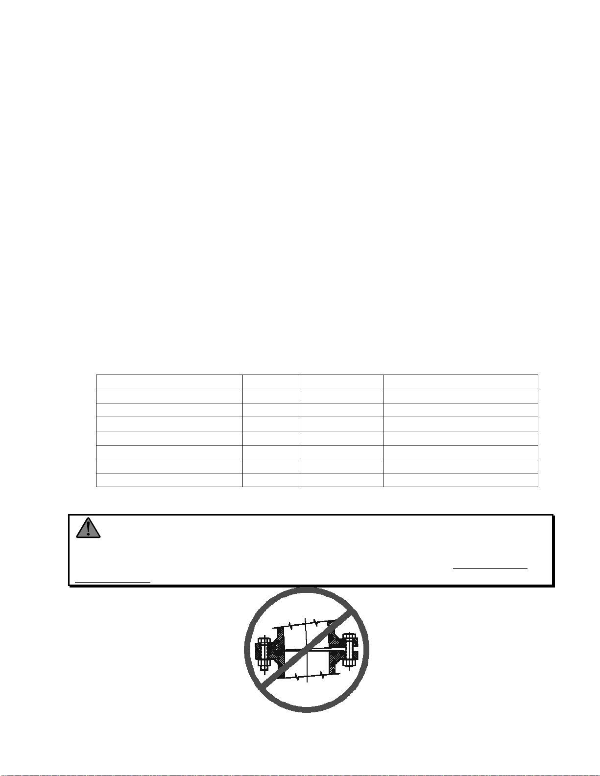
Warning: When installing monitor on a raised face companion flange or butterfly
valve, it is critical that bolts be tightened uniformly to prevent cocking of the monitor relative to the
flange or valve. If the monitor becomes cocked, (see Figure 1) the monitor cast flange base will
fracture and fail when the bolts on the "high" side are tightened.
Figure 1
Improper Flange Installation
Page 2
Page 5

III. OPERATING
1. Tiller Handle Monitor
The tiller handle monitor comes with both a left/right and an up/down lock
handle. See Figure 2. To disengage lock(s), turn handle(s)
counterclockwise. Move the tiller handle to direct the stream to the
desired position. Turn lock handle(s) clockwise to engage lock.
Figure 2
2. Wheel Handle Monitor
The wheel handle monitor comes with both a left/right and an up/down
lock handle. See Figure 2. To disengage lock(s), turn handle(s)
counterclockwise. Move the wheel handle to direct the stream to the
desired position. Turn lock handle(s) clockwise to engage lock.
Page 3
Page 6

IV. MAINTENANCE & INSPECTION
The monitor should be inspected regularly. Careful inspection for damage to
the monitor or nozzle is especially important after use in emergency
operations.
Flow water to check nozzle pattern. If pattern is disrupted, remove nozzle and
check for debris lodged between the nozzle stem and body, or in the stream
shaper inlet.
During nozzle flow test, inspect monitor swivel joints for leaks.
Note: Although grease fittings are provided for the up-down and left-right
gear cases, routine greasing should not be necessary. If the monitor is
exposed to a high level of radiant heat for a prolonged period, it may be
possible for the factory grease to thin and run out of the swivel joints. In such
an event, fresh grease should be applied.
Page 4
Page 7

V. PARTS DRAWINGS
Page 5
Page 8

Page 6
Page 9

Page 7
Page 10

Page 8
Page 11

VI. MONITOR & STREAM SHAPER
299-11 Python Monitor Losses
25
20
15
10
Pressure (PSI)
Friction Loss is Equal to
Total Static Pressure
Drop
5
0
200 300 400 500 600 700 800 900 1000 1100 1200
Flow Rate (GPM)
Total Static Pressure Drop
Friction Loss for Monitor
Page 9
Page 12

w
Elkhart Brass Mfg. Co., Inc.
Mailing Address:
P.O. Box 1127
Elkhart, IN 46515 USA
Shipping Address:
1302 W. Beardsley Ave.
Elkhart, IN 46514 USA
Tel. 1-574-295-8330
1-800-346-0250
Fax 1-574-293-9914
e-mail: info@elkhartbrass.com
ww.elkhartbrass.com
98436000 Rev. Rel
 Loading...