

Page 1
1302 West Beardsley Ave. • Elkhart, IN USA 46514 • 574.295.8330 • Fax 574.293.9914
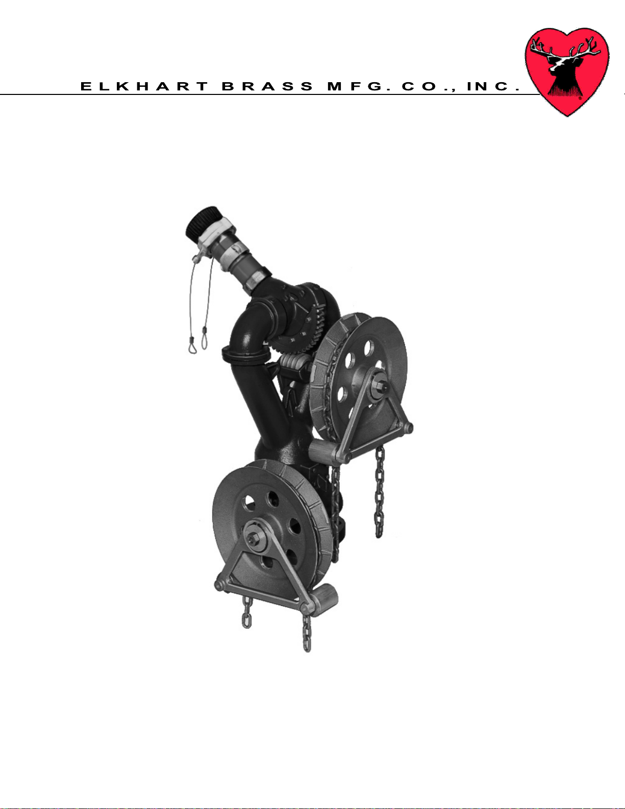
Installation, Operating &
Maintenance Instructions
Model 294-11-CW and 294-11-CWB
98443000 Rev. Rel November 15, 2006
Page 2

Page 3
I. Product Safety
1. All Personnel who may be expected to use this equipment must be thoroughly trained in its
safe and proper use.
2. Before flowing water from this device, check that all personnel (fire service and civilian) are out
of the stream path. Also, check to make sure stream direction will not cause avoidable
property damage.
3. Become thoroughly familiar with the hydraulic characteristics of this equipment, and the
pumping system used to supply it. To produce effective fire streams, operating personnel
must be properly trained.
4. Open water valve supplying this equipment slowly, so that the piping fills slowly, thus
preventing possible water hammer occurrence.
5. After each use, and on a scheduled basis, inspect equipment per instructions in the
Maintenance & Inspection section of this manual.
Warning: The piping must be able to withstand a horizontal force of at least 1-1/2 times the
nozzle reaction force at the height of the vertical swivel joint center and from any angle of rotation that the
monitor is capable of turning. Serious injury to personnel and equipment can result from improper
installation.
Page 4

II. Installation Instructions
1. How to Determine Nozzle Reaction Force
It is important to note that the piping must be able to withstand a horizontal force of at least
1-1/2 times the nozzle reaction force at the height of the vertical swivel joint center and
from any angle of rotation that the monitor is capable of turning.
The nozzle reaction formula for smooth bore nozzles is NR = 1.5 x d
The nozzle reaction formula for combination fog nozzles is NR = 0.0505 x Q x √P
Where NR = Nozzle Reaction (in pounds)
d = Nozzle Discharge Diameter (inches)
NP = Nozzle Pitot Pressure (psi)
Q = Flow (in GPM)
P = Nozzle Pressure (in PSI at nozzle inlet)
1.5 and 0.0505 are constants
An example of a 1-7/8” smooth bore nozzle flowing with a Pitot measuring 95 psi will have a
reaction force of 501 lbs.
The combination fog nozzle formula is with the nozzle set on straight stream. Reaction will
decrease as the stream pattern is widened to fog. For example, a combination fog nozzle
discharging 1000 GPM @ 100 PSI in a straight stream will have a reaction force of 505 lbs.
Maximum nozzle reaction force is 505 lbs.
Maximum monitor inlet pressure is 200 psi.
2. Monitor with NPT Base
Apply an appropriate thread sealant to the NPT nipple on the water supply pipe. Thread the
monitor base onto the nipple.
3. Monitor with Flat Faced Flange
a) Attach an ANSI pattern flat face companion flange to the water supply pipe.
b) Seal the flange joint with a full face gasket or suitable flange sealant.
c) Attach the monitor inlet flange to the companion flange on the water supply pipe with grade
5 carbon steel or stainless steel bolts with nuts. A 4.0” 150# ANSI flange requires eight
5/8” – 11 UNC bolts, minimum 2 ½” long.
d) Apply Loctite® #242 to the bolt threads, then thread on the nuts, and torque the flange bolts
to 60-70 ft-lbs uniformly increments of approximately 20 ft-lbs.
2
x NP
Warning: When installing monitor on a raised face companion flange, it is critical that bolts be
tightened uniformly to prevent cocking of the monitor relative to the flange. If the monitor becomes cocked,
(see Figure 1) the monitor cast flange base will fracture and fail when the bolts on the "high" side are
tightened.
Page 5

Figure 1
Improper Flange Installation
3. Chain Installation on monitor (0.250” non-magnetic aluminum chain required,
McMaster Carr part number 3620T21)
a) Vertical movement
(1) Remove spring clip (item #12 on attached drawing) P/N 57681
(2) Slide chain wheel guide off shaft
(3) Find middle point on length chain and hang onto the Chainwheel
(4) Slide chain wheel guide back onto shaft
(5) Reinstall spring clip
b) Horizontal movement
(1) Repeat above steps 1-5
4. Install model 282B stream shaper (if provided) onto monitor discharge. Tighten with spanner
wrench
5. Install model CJ-B-RC or CJN-B-RC onto 282B or monitor discharge with the slotted boss on
the body centered on the underside of the nozzle when the monitor’s discharge is at the 90
degree angle to the water supply piping. Tighten with spanner wrench
Page 6

CJ-B-RC or
CJN-B-RC
Nozzle
Stream Pattern
Control Cables
Horizontal
Movement
Chain wheel
Vertical
Movement
Chain wheel
Chain Wheel
Guides
III. Operation
1. The upper Chainwheel controls the monitor’s vertical movement of 150 degrees (+90 to -60
degrees)
2. Rotating the upper Chainwheel clockwise will raise the nozzle elevation, a counter clockwise
movement lowers the nozzle elevation
3. The lower Chainwheel rotates the monitor a full 360 degrees.
4. Rotating the lower Chainwheel clockwise will rotate the monitor to the right, a counter
clockwise movement moves the monitor to the left
5. Stream pattern adjustment is accomplished by pulling on the cable guides attached to the
nozzle
Page 7

IV. Maintenance
1. Monitor should be inspected on a monthly basis.
2. Careful inspection should be conducted after use during emergency operations.
3. Exercise monitor by moving it thru its entire range of motion once a month to assure that
monitor is operating properly, preferably with water flowing at the rated volume and pressure.
4. Inspect gearing for proper lubrication. A heavy coating of silicone grease (Dow Corning #4
compound MIL-SC-8660B or equal) should be maintained on gears, especially in corrosive
environments or in freezing temperatures.
5. Grease the unit every three months thru all grease fittings until all contaminated grease is
expelled. Use a good grade waterproof grease. Wipe off expelled grease.
6. Flow test to check nozzle stream performance. If pattern is disrupted, remove nozzle and
stream shaper (if provided) and check for debris lodged in nozzle or stream shaper inlet
7. During nozzle flow test, inspect monitor swivel joints for leaks
8. Maintain paint as dictated by environment conditions.
Page 8

Δ
V. Monitor & Nozzle Hydraulic Data
Interpreting Flow Data
The following graphs offer the pressure losses for the monitor (and other devices) in terms of Total
Static Pressure Drop. This Total Static Pressure Drop can be found by measuring the difference
between the static inlet pressure and the static outlet pressure. The static pressure at either of these
points can be found using a simple pressure gauge. An illustration of this method can be seen below.
In mathematical terms, the Total Static Pressure Drop is the change in Velocity Pressure plus Friction
Loss. The change in Velocity Pressure results from the change in velocity of water caused by the
change in the cross section of a waterway. Friction Loss results from the drag and sidewall
interference of the water through a device. A simple equation can be seen below.
ΔPS = HF + ΔP
ΔPS = Total Static Pressure Drop
H
= Friction Loss
F
P
= Velocity Pressure Loss
V
In the firefighting industry, the terms Total Static Pressure Drop and Friction Loss tend to be used
interchangeably. However, these are significantly different measurements. This misconception could
ultimately lead to lower than anticipated performance from equipment. When designing a system
and determining performance, Total Static Pressure Drop is the value that should always be
used. The Friction Loss curve is also supplied in order to make a comparison with competitor
products that may only supply Friction Loss curves. If there are any further questions regarding this
matter, please contact Elkhart Brass.
Page 9

Page 10

w
Elkhart Brass Mfg. Co., Inc.
Mailing Address:
P.O. Box 1127
Elkhart, IN 46515 USA
Shipping Address:
1302 W. Beardsley Ave.
Elkhart, IN 46514 USA
Tel. 1-574-295-8330
1-800-346-0250
Fax 1-574-293-9914
e-mail:
info@elkhartbrass.com
ww.elkhartbrass.com
 Loading...