

Page 1
98086010 Rev-C (ECN 120227)
IMPORTANT
Pass Instructions On To End User
Page 2

Page 3

Table of Contents
I. PRODUCT SAFETY ……………………………………………………3
II. SYSTEM DISCRIPTION ……………………………..…………………4
III. VALVE OPERATION …………………………………………………..4
A. AUTO TRAVEL: …………………………………………………….4
B. INDICATOR LIGHT SIGNALS …………………………………….5
C. OTHER CONTROL FEATURES ……………………………………5
IV. ELECTRICAL SPECIFICATIONS ………………………………………6
V. INSTALLATION INSTRUCTIONS ……………………………………..6
A. VALVE INSTALLATION ……………………………………………6
B. VALVE CONTROLLER AND POSITION INDICATOR …………..9
C. INTERCONNECTING HARNESSES ……………………………..…9
D. PRIMARY/SECONDARY CONTROLLER OPTION …………..… 9
VI. TROUBLESHOOTING ………………………………………………….10
VII. SYSTEM LAYOUT DRAWINGS …….…………………………………11
2
Page 4
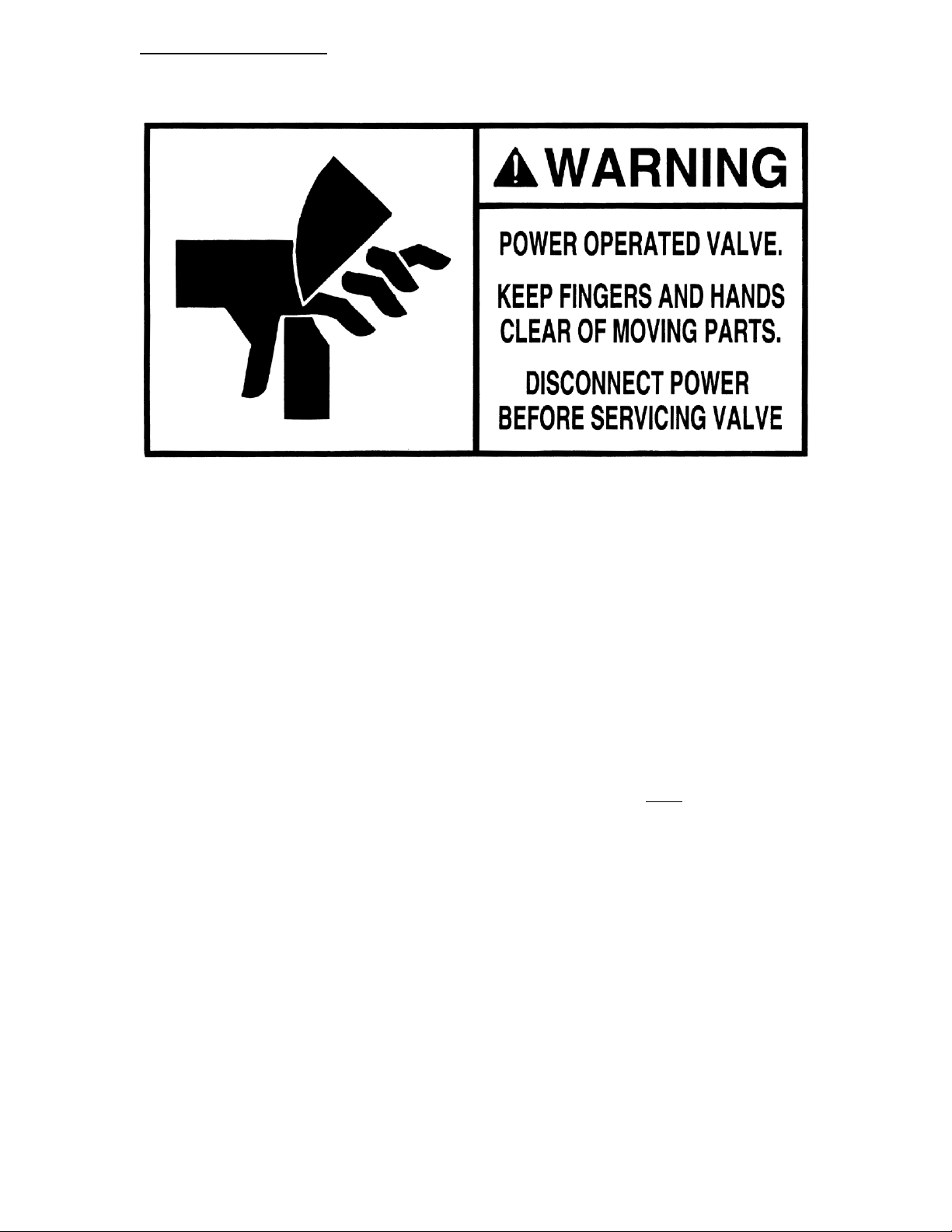
I. PRODUCT SAFETY:
It is critical to the safety of installers, users and bystanders that the following precautions
are followed:
1. Keep fingers and hands clear of the valve waterway whenever power is
connected to the valve.
2. Be certain that the valve motor power is disconnected prior to servicing the
valve.
Motor power can be disconnected by pulling apart the small, twoconductor automotive type wire connector near the valve motor.
3. Whenever valves are installed near hose connections, such that fingers or
hands could reach the valve ball or disc, a screen or strainer must be installed in
the waterway between the hose connection and the valve.
An adhesive backed warning label, which is supplied with each valve
(25024000), should be applied to the pump panel or apparatus body
adjacent to the hose connection controlled by an electrically operated
valve.
4. A warning label is applied to each valve motor. This label includes a peel-off
paint mask. It is important that this mask be removed prior to the apparatus being
placed into service.
3
Page 5

II. SYSTEM DESCRIPTION:
The 2900E series electrically actuated valve line includes a complete range of ball valve
sizes including 1-1/2”, 2”, 2-1/2”, 3”, and 4”, and butterfly valves in 2”, 3”, 4”, 5”, and
6” sizes. The valve opening and closing actions are controlled by a bronze worm gear
case driven by a 12 volt DC gear motor. One size gear motor and gear case assembly is
used on the 1-1/2”, 2”, and 2-1/2” ball valves and a larger gear motor and gear case are
used on the 3” and 4” ball valves and all sizes of butterfly valves.
Each motor-driven valve is coupled to a combined valve controller and position indicator
module (81384001), which includes motor power relays and provides several important
operating features. This module is sealed from the environment as long as all harnesses,
which use sealed connectors, are connected. The front panel of this module contains two
pushbuttons, used to operate the valve, and three high intensity LED’s, which indicate the
valve’s position. Intermediate harnesses from the module to the valve are available from
Elkhart Brass in several standard lengths. See Layout Drawings for part numbers.
III. VALVE OPERATION:
The push buttons on the panel-mounted module (81384001) are used to fully open and
close the valve or to place the valve in a throttled position. The pushbuttons are color
coded for quick interpretation and offer tactile feedback to the user. Pushing the green
open button will cause the valve to travel in the open direction, and pushing the red
button will cause the valve to travel in the closed direction. When opening the valve
from the fully closed position, there is a momentary delay to prevent the valve from being
cracked opened by an inadvertent push of the open button.
Hall Effect transducers located in the valve gear case precisely sense the valve open and
closed positions. The Hall sensors are digital, solid state devices that provide a switching
signal in the presence of a magnetic field. As the valve reaches either the open or closed
position, a small magnet moves into the sensing range of the Hall device. The Hall
device then changes state and causes motor power to shut off. This control feature
prevents high current, high torque stall loading of the motor and gear train.
A. Auto-Travel Feature:
A unique and valuable feature of the 2900E control system is its “Auto-Travel”
capability. The travel time from the fully closed to the fully open position is seven
seconds for all valve sizes. This travel speed assures precise valve throttling control, and
assures against rapid closure of the valve and the associated water hammer potential. The
Auto-Travel feature allows the pump operator to either fully open or fully close the valve
without the need to hold the pushbutton for seven seconds.
Auto-Travel can be initiated with the valve in any position. To initiate Auto-Travel the
operator holds down the pushbutton corresponding to the desired direction of travel.
While holding this button, the operator presses and releases the other button. Finally, the
operator releases the button corresponding to the desired direction of travel. The valve
will continue to travel in the desired direction until it reaches the fully open or fully
closed position. For the properly trained pump operator this feature is easy to use, but it
is highly unlikely that a less experienced operator will accidentally initiate Auto-Travel.
Once Auto-Travel has been initiated, pressing either button will cancel the operation.
4
Page 6

B. Indicator Light Signals:
This will void all warran
ties.
The valve controller/position indicator module (81384001) uses three high intensity
LED’s, red, amber, and green, for reliable status indication under all ambient lighting
conditions. These LED’s provide the following signals to the operator:
SIGNAL MEANING
Steady lit red Valve ball in the fully closed position
Steady lit green Valve ball in the fully open position
Steady lit amber Valve ball is in a throttled position
Steady lit amber with flashing green Valve ball is moving toward the open position
Steady lit amber with flashing red Valve ball is moving toward the closed position
C. Other Control Features:
Low Voltage Protection:
Should the valve power source voltage ever drop to six volts or less, the control module
automatically prevents application of power to the motor. Low voltage conditions can
cause serious damage to DC motors.
Automatic Power Off:
If the valve becomes jammed (ice, debris, or any other reason) while the valve is in AutoTravel, this feature will automatically shut off motor power after fifteen seconds.
Manual Valve Actuation:
If valve motor power fails for any reason, the valve can be opened or closed manually.
Manual actuation is accomplished by turning the hex fitting on the end of the worm drive
shaft opposite the motor. Turning the hex fitting clockwise will open the valve, while
turning it counterclockwise will close the valve. A ¾” ratchet box end, standard box end
or open-end wrench is recommended for this purpose.
NOTE: DO NOT use any motorized or air actuated devices to drive the hex fitting.
Reverse Polarity Protection:
The circuitry within the 81384001 control module is designed to be immune to the effects
of reversed polarity of the incoming power. If polarity is reversed at the time of system
installation or any time during system maintenance or troubleshooting, no damage will
result. None of the LED’s will light up and the unit will not function during polarity
reversal.
5
Page 7

IV. ELECTRICAL SPECIFICATIONS:
Valve Type
Nominal Operating Voltage 12 VDC
Operating Voltage Range 11-15 VDC (RECOMMENDED FUSE RATING 10A)
Normal Operating Current 3 A 1.5 A
Motor Stall Current 13 A 11.9 A
Operating Temperature Range -40°F to 150°F
V. INSTALLATION INSTRUCTIONS:
A. Valve Installation:
The 2900E ball valves sizes 1.5” through 3.0” are bi-directional and can be installed in
either direction. The 2940E 4.0” valve should be installed with the arrow on the body
pointing in the direction of flow except in a tank to pump application where the arrow
should be pointing towards the tank. The 2950E butterfly valves are bi-directional and
can be installed in either direction. The 2960E butterfly valves should be installed with
the seat towards the pressure source.
3” and 4” Ball Valves
All Butterfly Valves
1.5”, 2.0”, and 2.5”
Ball Valves
NOTE: Some older 2-1/2” ball valve end caps have stepped recesses on the valves’
mating surfaces. These stepped endcaps cannot be used with the 2900 valves.
Replace these endcaps with new flat surface endcaps.
Motor/Gear Case Repositioning:
The 2900E ball valve and the 2960E butterfly valve gear cases may be installed in one of
four positions relative to the valves assemblies’ inlet as shown in Figure 1. There are two
possible positions for the gear cases used on the 2950E butterfly valves as shown in
Figure 2. Since these valves are bi-directional each position can be mounted two ways.
The valves shown in Figures 1 and 2 are in the fully closed position If installation
interference is encountered due to gear case position, the following steps will allow
simple repositioning of the gear case:
6
Page 8

NOTE: Valve actuators should be positioned to provide best access to the ¾” hex manual override nut.
Ball Valves;
1. Place the valve in the fully closed position. Note that the slot in the end of the actuator
shaft shows the position of the ball. When the slot is at a right angle to the waterway, the
valve is fully closed.
2. Remove the four socket head cap screws from the gear case cover, and then pull the
cover from the gear case. Rotating the cover slightly will ease removal.
3. Remove the thrust washer and gear segment from the gear case. Note that rotating the
worm slightly will ease gear segment removal.
4. Remove the four socket head cap screws that secure the gear case to the valve body.
Do not remove the stop plate from the actuator shaft.
5. Rotate the gear case to the desired position. (Note: Inspect the O-ring between the
gear case and the valve body for any damage and proper location.)
7
Page 9

6. Apply Loctite #242 to the four screws and reinstall them to secure the gear case to the
valve body. Torque the screws to 120-150 in-lbs.
7. Install the gear segment in the correct position as shown in Figure 1 above. Note that
rotating the worm slightly will ease gear segment installation.
8. Apply petroleum base grease to the thrust washer and install.
9. Reassemble the gear case cover on the gear case taking care not to damage the cover
O-ring.
10. Apply Loctite #242 to the four socket head cap screws and reinstall and tighten them
to secure the gear case cover.
Butterfly Valves;
1. Place the valve in the fully closed position. Note that the slot in the end of the actuator
shaft shows the position of the disc. When the slot is at a right angle to the waterway, the
valve is fully closed.
2. Remove the four socket head cap screws from the gear case cover, and then pull the
cover from the gear case. Rotating the cover slightly will ease removal.
3. Remove the thrust washer and gear segment from the gear case. Note that rotating the
worm slightly will ease gear segment removal.
4. Remove the four hex head bolts that secure the gear case assembly to the mounting
flange on the valve body.
5. Rotate the gear case assembly to the desired position while making sure the valve
remains closed.
6. Apply Loctite #242 to the four hex head bolts then reinstall and tighten them to secure
the gear case assembly to the mounting flange on the valve body.
.
7. Install the gear segment in the correct position as shown in Figure 2 above. Note that
rotating the worm slightly will ease gear segment installation.
8. Apply petroleum base grease to the thrust washer and install.
9. Reassemble the gear case cover on the gear case taking care not to damage the cover
O-ring.
10. Apply Loctite #242 to the four socket head cap screws and reinstall and tighten them
to secure the gear case cover.
8
Page 10

B. Valve Controller and Position Indicator Module:
The 81384001 valve controller and position indicator module is to be installed in the
pump control panel. The panel cutout template is shown on the layout drawing. The
module is secured to the pump panel with four split lock washers and four #6-32 stainless
steel small pattern nuts (1/4” socket driver), which are provided with the module. The
pressure gage for each discharge valve should be installed above the 81384001 module
controlling that valve. A harness is included with each control module and is to be
connected to the back of the module. This harness contains two male connectors; one for
supply power, and one that is to be connected to the valve via an intermediate harness.
NOTE: The 81384001 module is only sealed from the environment when all harnesses
are plugged in.
Power Source:
It is recommended that power to all 81384001 valve control modules be controlled by a
single switch/relay combination so that power can be shut off unless the apparatus is in
pumping mode. Automatic reset circuit breakers must be installed between the power
source and the 81384001 modules. A breaker rating of 10 amps is recommended, and
two modules may be powered through a single breaker. Each 81384001 module includes
an input power connector with red and black wire leads as shown in electrical layout
drawing. The leads have crimp connectors with heat shrink tubing. Strip about 5/16” of
insulation from the power source wire and insert it into the crimp connector of the red
lead on the supplied power connector. Secure the wire lead in the crimp connector with a
suitable crimper. Similarly, strip and crimp the ground wire to the black lead on the
supplied power connector (Chassis ground is not recommended). After crimping, use a
heat gun or another heat source to shrink the plastic sleeves until the adhesive melts and
flows to seal the connections.
C. Interconnecting Harnesses:
Interconnecting harnesses are provided in several lengths to connect the 81384001 valve
controller and position indicator module and the valve assembly. See Layout Drawing
for a complete list of harness lengths. These harnesses should be carefully secured to the
vehicle frame or other structural members to protect them from abrasion due to vibration.
Also, they must not be installed where they could be exposed to temperatures over 160°F.
The harnesses must be supported near all connections.
D. Primary/Secondary Controller Option:
The option exists to control a single valve with two controllers. The controllers may be
located in different locations on a truck. The dual controller option functions with the use
of a primary controller that is connected to the valve via a power/sensor harness. The
secondary controller does not utilize a power/sensor harness; rather it is connected to the
primary controller by a primary/secondary harness. The secondary harness sends a signal
to the primary controller that controls the valve. The primary controller will override the
secondary controller. Refer to the Primary/Secondary Layout Drawing for wiring
diagram and harness length options. Primary and Secondary controllers must share a
common ground (Chassis ground is not recommended).
9
Page 11

VI. TROUBLESHOOTING:
Problem Possible Cause Solution
No LED’s light
(no valve function)
Alternating flashing red
and green LED’s when
first powered up
(no valve function)
Alternating flashing red
and green LED’s when
open or close button is
being pushed
(no valve function)
Both red and green LED’s
on steady
(no valve function)
Flashing yellow LED
Red or green LED’s will
not stay lit. Red or green
LED flashes when
operating the valve
LED will not light
Valve will not open or
close. Lamp flashes,
showing direction, but
valve does not move
Power not being supplied to
module
Module supply power polarity is
reversed
Defective switch in controller
Low voltage under load Check for good power & ground under load
Defective Hall sensor circuit
board in valve gear case
Short in signal wire (orange
and/or yellow) between valve
and module
Auto-Travel has timed out after
15 seconds
Defective Hall sensor circuit
board
Defective signal wire (orange or
yellow) between valve and
module
Burned out LED Replace module
Failed Hall sensor circuit board
Damaged or broken wires
between valve controller and
valve
Motor assembly not plugged into
harness
Gear segment not in correct
position
Motor is burned up
Turn on power to module and check circuit
breaker
Correct power input wires
Replace controller (Note: must specify whether
controller is a primary or secondary when
ordering)
Unplug connector at circuit board (mounted to
bottom of gear case cover); if yellow LED comes
on replace circuit board
Remove harnesses starting at the valve and
working back. Replace the last harness you
unplug before the yellow LED comes on
Hall sensor failure; replace circuit board. Valve
jammed; remove debris from waterway. Motor
failure; replace motor and look for cause of failure
Remove gear case cover. With system power on,
hold magnet over sensor and check for steady
burning red or green LED. If both LED’s don’t
light in presence of magnet, replace circuit board
Check harness for broken or frayed wires and
examine connectors and/or loose contact crimps
Replace circuit board located on bottom of valve
gear case cover
Check all wires and connections for damage
Check two prong molded connector at valve and
reconnect
Reference motor/gear case repositioning Figures 2
& 3
Remove motor sub from valve and apply 12 VDC
to motor. If motor does not operate, replace
10
Page 12

VII. SYSTEM LAYOUT DRAWINGS
11
Page 13

12
 Loading...