

Page 1
i
Page 2

Page 3

Preface
©Copyright 2005
©
All Rights Reserved.
The information in this document is subject to change without prior
notice in order to improve reliability, design and function and does
not represent a commitment on the part of the manufacturer.
In no event will the manufacturer be liable for direct, indirect,
special, incidental, or consequential damages arising out of the
use or inability to use the product or documentation, even if
advised of the possibility of such damages.
This document contains proprietary information protected by
copyright. All rights are reserved. No part of this manual may be
reproduced by any mechanical, electronic, or other means in any
form without prior written permission of the manufacturer.
Trademarks
AutoCAD and Autoshade are trademarks of Autodesk, Inc. IBM,
OS/2, and VGA are trademarks of International Business Machines
Corp. Lotus, 1-2-3, and Symphony are trademarks of Lotus
Development Corp. Windows, Word, MS-DOS, and Microsoft are
trademarks of Microsoft Corp. VESA is a trademark of Video
Electronics Standards Association.
Other product names mentioned herein are used for identification
purposes only and may be trademarks and/or registered
trademarks of their respective companies.
Limitation of Liability
While reasonable efforts have been made to ensure the accuracy
of this manual, the manufacturer and distributor assume no liability
resulting from errors or omissions in this manual, or from the use of
the information contained herein.
i
Page 4

Notices
Federal Communications Commission Radio Frequency
Interference Statement
This equipment has been tested and found to
comply with the limits for a Class B digital device, pursuant to Part
15 of the FCC Rules. These limits are designed to provide reasonable
protection against harmful interference in a residential installation.
This equipment generates, uses, and can radiate radio frequency
energy and if not installed and used in accordance with the
instruction manual may cause harmful interference to radio
communications. However, there is no guarantee that interference
will not occur in a particular installation. If this equipment does
cause harmful interference to radio or television reception, which
can be determined by turning the equipment off and on, the user is
encouraged to try to correct the interference by one or more o f the
following measures:
` Reorient or relocate the receiving antenna
` Increase the separation between the equipment and receiver
` Connect the equipment into an outlet on a circuit different from
that to which the receiver is connected
` Consult the dealer or an experienced radio TV technician for
help
This device complies with Part 15 of the FCC Rules. Operation is
subject to the following two conditions: (1) This device may not
cause harmful interference, and (2) this device must accept any
interference received, including interference that may cause
undesired operation.
FCC Caution: Any changes or modifications not expressly
approved by the party responsible for compliance could void the
user's authority to operate this equipment.
IMPORTANT NOTE: FCC Radiation Exposure Statement:
This equipment complies with FCC radiation exposure limits set
forth for an uncontrolled environment. This equipment should be
installed and operated with minimum distance 20cm between the
radiator & your body. To maintain compliance with FCC RF
exposure compliance requirements, please avoid direct contact to
the transmitting antenna during transmitting.
ii
Page 5

If this device is going to be operated in 5.15 ~ 5.25GHz frequency
range, then it is restricted in indoor environment only.
This transmitter must not be co-located or operating in conjunction
with any other antenna or transmitter.
We declares this product (FCC ID: XXXXXXXXXXXX) is limited in
2412~2462MHz by specified firmware controlled in the USA.
EC DECLARATION OF CONFORMITY (EUROPE)
Hereby, we declares that this product is in compliance with the
essential requirements and other relevant provisions of Directive
1999/5/EC as listed below
Article 3.1(a): EN 60950, EN50392
Article 3.1(b): EN 301 489-1, EN 301 489-17
Article 3.2: EN 300 328, EN 301 893
Caution:
This equipment is intended to be used in all EU and EFTA
countries. Outdoor use may be restricted to certain frequencies
and/or may require a license for operation. Contact local Authority
for procedure to follow. Note: Combinations of power levels and
antennas resulting in a radiated power level of above 100 mW
equivalent isotropic radiated power (EIRP) are considered as not
compliant with the above mentioned directive and are not allowed
for use within the European community and countries that have
adopted the European R&TTE directive 1999/5/EC.
0976
EUROPE – RESTRICTIONS FOR USE OF 5GHZ
FREQUENCIES IN EUROPEAN COMMUNITY COUNTRIES
Regulatory statement (R&TTE / WLAN IEEE 802.11abg)
Operation of this device is subjected to the following recommended
National regulations and may be prohibited to use if certain
restriction should be applied, please check local regulatory
authority for the most updated info before operating the device.
iii
Page 6

National Restrictions
Data based on ERC RECOMMENDATION 70-03 (November 2005).
2400-2483.5 MHz
Country Restriction Reason / remark
Bulgaria
France Outdoor use limited
to 10 mW e.i.r.p.
within the band
2454-2483.5 MHz
Italy
Luxembourg None General authorization required for
Romania On a secondary
basis. Individual
license required.
T/R 22-06 not
implemented
5150-5250 MHz
Belgium Not implemented
Bulgaria Not implemented Planned
Croatia License required
Cyprus Not implemented Under study
Germany Not implemented
Greece Not implemented
Italy General authorization required if
Liechtenstein Not implemented
Luxembourg None General authorization required for
Portugal Not implemented
Romania Not implemented
Slovak
Republic
Spain Not implemented
5250-5350 MHz
Belgium Not implemented
Bulgaria Not implemented Planned
Croatia License required
Cyprus Not implemented Under study
Germany Not implemented
Greece Not implemented
Not implemented
General authorization required for
outdoor use and public service
If used outside of own premises,
general authorization is required
public service
used outside own premises
public service
iv
Page 7

Italy General authorization required if
used outside own premises
Liechtenstein Not implemented
Luxembourg None General authorization required
for public service
Portugal Not implemented
Romania Not implemented
Slovak
Republic
Spain Not implemented
5470-5725 MHz
Austria Not implemented
Belgium Not implemented
Bulgaria Not implemented Planned
Cyprus Not implemented Under study
France Not implemented France will implement this band
Germany Not implemented
Greece Not implemented
Ireland Not implemented
Italy General authorization required if
Liechtenstein Not implemented
Luxembourg None General authorization required
Macedonia
(Rep of)
Portugal Not implemented
Romania Not implemented
Slovak
Republic
Spain Not implemented
Turkey Not implemented Military services
Not implemented
identified by the
ERC/DEC(99)23, when the
efficiency of the mitigation
techniques made mandatory by
this Decision is ensured
used outside own premises
for public service
Not implemented Will be implemented soon
Not implemented Military services
` To remain in conformance with European spectrum usage
laws for Wireless LAN operation, the user should check the
current channel of operation. If operation is occurring outside
of the allowable frequencies as listed above, the user must
cease operating at that location and consult the local technical
support staff responsible for the wireless network.
v
Page 8

` The 5GHz Turbo mode feature is not allowed for operation in
any European Community country
` This device must not be operated in ad-hoc mode using
channels in the 5GHz bands in the European Community. Adhoc mode provides a direct communication between two client
devices without a Wireless LAN Access Point.
` This device must be used with Access Points that have
employed and activated a radar detection feature required for
European Community operation in the 5GHz bands. This
device will operate under the control of the Access Point in
order to avoid operating on a channel occupied by any radar
system in the area. The presence of nearby radar operation
may result in temporary interruption in communications of this
device. The Access Point’s radar detection feature will
automatically restart operation on a channel free of radar. You
may consult with the local technical support staff responsible
for the wireless network to ensure the Access Point device(s)
are properly configured for European Community operation.
Notice:
Changes or modifications not expressly approved by the party
responsible for compliance could void the user’s authority to
operate the equipment. Shielded interface cables and a nonshielded AC power cord must be used in order to comply with
emission limits.
This equipment is to be used with power supply: 65W
There is no internal power supply.
vi
Page 9

Table of Content
BEFORE YOU START ...............................................................................1
SAFETY COMPLIANCE NOTICE..............................................................1
EUROPE – EU DECLARATION OF CONFORMITY.........................2
LET YOUR COMPUTER ACCLIMATE ITSELF ..............................................9
HEAT, COLD, HUMIDITY, AND GLARE ....................................................9
SUITABLE PLACE TO WORK...................................................................9
INTRODUCTION......................................................................................11
POWERING UP THE TABLET PC ..........................................................11
FRONT SIDE FEATURES .....................................................................12
TOP SIDE FEATURES .........................................................................13
RIGHT SIDE FEATURES ......................................................................15
LEFT SIDE FEATURES ........................................................................15
THE BACK SIDE FEATURES ................................................................16
APPLICATION BUTTONS......................................................................17
NAVIGATION BUTTONS.......................................................................17
TOUCHPAD BUTTONS ........................................................................17
GETTING STARTED ...............................................................................21
CONNECTING THE AC ADAPTER .........................................................21
TURNING ON YOUR COMPUTER .........................................................22
OPERATING ON BATTERY POWER.......................................................22
USING THE COMPUTER..........................................................................25
THE BATTERY POWER SYSTEM ..........................................................26
REMOVING THE BATTERY PACK..........................................................26
WRITING AREA ..................................................................................30
USING THE SCREEN KEYBOARD .........................................................30
ON SCREEN KEYBOARD.....................................................................30
WRITING PAD ....................................................................................30
CHARACTER PAD ...............................................................................31
CALIBRATION < 4 PTS CAL >...............................................................33
ADVANCED < 25 PTS CAL > ................................................................33
HELP WINDOWS ................................................................................34
DESKTOP ..........................................................................................34
CONTROL PANEL...............................................................................36
DESKTOP OPERATION...........................................................................37
THE MULTIMEDIA SOUND SYSTEM......................................................37
AUDIO VOLUME CONTROL..................................................................37
AUDIO SOFTWARE .............................................................................38
SOUND RECORDING ..........................................................................39
PLAYING SOUND FILES ......................................................................39
vii
Page 10

EXTERNAL SPEAKERS AND MICROPHONE ...........................................39
INTERNET CONNECTION (OPTIONAL)......................................................41
RUNNING BIOS SETUP .........................................................................49
ITEM SPECIFIC HELP..........................................................................49
THE LEGEND BAR..............................................................................50
LAUNCHING SUBMENUS .....................................................................51
GENERAL HELP .................................................................................51
VGA UTILITIES.....................................................................................57
INTEL (R) GRAPHICS MEDIA ACCELERATOR DRIVER FOR MOBILE ........58
VIDEO CONFERENCING (OPTION)...........................................................61
USING COMMANDS AND BUTTONS ......................................................62
TROUBLESHOOTING ..............................................................................67
SYSTEM NOT RESUMING OPERATION .................................................68
DISPLAY SCREEN IS BLANK OR DIFFICULT TO READ ............................68
TABLET PC IS NOT RESPONDING TO THE PEN.....................................68
THE TABLET PC CAN NOT POWER ON ................................................69
THE CURSOR NOT IN POSITION WHILE USING THE ORDINARY PEN ..........69
THE COMPUTER IS UNABLE TO CONNECT TO THE INTERNET..................69
NO SOUND ON THE EXTERNAL SPEAKERS OR HEADPHONES..................69
BEEPING SOUND................................................................................69
IF THE CURSOR IS NOT IN POSITION WITH THE TOUCH PEN ....................69
DOCKING STATION (OPTIONAL).............................................................71
FRONT SIDE FEATURE .......................................................................71
LEFT SIDE FEATURE ..........................................................................72
DOCKING RIGHT SIDE FEATURE .........................................................72
DOCKING REAR SIDE FEATURE ..........................................................73
SPECIFICATION.....................................................................................77
viii
Page 11

Canadian DOC Notice For Class B Computing Devices
This Class B digital apparatus meets all requirements of the
Canadian Interference - Causing Equipment Regulations.
Cet appareil numerique de la classe B repecte toutes les
exigences du Règlement sur le matèriel brouilleur du Canada.
Personal Inventory
This computer system is designed for years of productive and
pleasurable computing. Use this section to keep notes about
details of your purchase. Update this section when you add new
options.
Date of Purchase:
Dealer’s Name:
Phone:
Address:
E-Mail Address:
WWW Site:
Serial Number:
CPU Type:
Hard Disk Capacity:
Memory Capacity:
Optional Equipment:
ix
Page 12

Page 13

Before you Start
CONVENTIONS OF THIS MANUAL
Use this manual will help you get the most from your computer.
` If you are an experienced user of computers and/or Microsoft’s
Windows operating systems, you might find it useful to read
the Quick Start Guide that comes along with your accessories.
` If you are a less experienced user, you should through the
manual carefully before using your system.
Whether or not you are an experienced user, you should consult
on the Troubleshooting Chapter if you encounter any problems
with your computer.
This product incorporates copyright
protection technology that is protected by U.S. patents and other
intellectual property rights. Use of this copyright protection
technology must be authorized by Macrovision, and is intended for
home and other limited viewing uses only unless otherwise
authorized by Macrovision. Reverse engineering or disassembly is
prohibited.
REGULATORY STATEMENT SAMPLE
AFETY COMPLIANCE NOTICE
S
This device has been tested and certified according to the
following safety standards and is intended for use only in
Information Technology Equipment which has been tested to these
or other equivalent standards:
` EN 60950-1
1
Page 14

EUROPE – EU DECLARATION OF CONFORMITY
Hereby, xxx Corporation, declares that this Product is in
compliance with the essential requirements and other relevant
provisions of Directive 1999/5/EC.
EUROPE
EUROPEAN COMMUNITY COUNTRIES
– RESTRICTIONS FOR USE OF 2.4GHZ FREQUENCIES IN
This device may be operated indoors or outdoors in all countries
of the European Community using the 2.4GHz band: Channels 1 –
13, except where noted below.
` In Italy the end-user must apply for a license from the national
spectrum authority to operate this device outdoors.
` In Belgium outdoor operation is only permitted using the
2.46 – 2.4835 GHz band: Channel 13
` In France outdoor operation is only permitted using the 2.4 –
2.454 GHz band: Channels 1 – 7
EUROPE
EUROPEAN COMMUNITY COUNTRIES
Allowed Frequency
5.15-5.25GHz 36, 40, 44, 48 Austria
5.15-5.35GHz 36, 40, 44, 48, 52,
5.15-5.35 & 5.470-
5.725GH z
– RESTRICTIONS FOR USE OF 5GHZ FREQUENCIES IN
Bands
Allowed Channel
Numbers
56, 60, 64
36, 40, 44, 48, 52,
56, 60, 64, 100, 104,
108, 112, 116, 120,
124, 128, 132, 136,
140
Countries
Cyprus, Czech
Republic, France,
Hungary, Slovakia
Belgium, Bulgaria,
Denmark, Estonia,
Finland, Germany,
Greece, Iceland,
Ireland, Italy, Latvia,
Liechtenstein,
Lithuania,
Luxembourg, Malta,
Netherlands, Norway,
Poland, Portugal,
Slovenia, Spain,
Sweden, Switzerland,
U.K.
` This device may not be operated outdoors when using the
bands 5150-5350MHz (Channels 36, 40, 44, 48, 52, 56, 50,
64).
2
Page 15

` In Italy the end-user must apply for a license from the national
spectrum authority to operate this device outdoors.
` To remain in conformance with European spectrum usage
laws for Wireless LAN operation, the above 5GHz channel
limitations apply. The user should check the current channel of
operation. If operation is occurring outside of the allowable
frequencies as listed above, the user must cease operating at
that location and consult the local technical support staff
responsible for the wireless network.
` The 5GHz Turbo mode feature is not allowed for operation in
any European Community country
` This device must not be operated in ad-hoc mode using
channels in the 5GHz bands in the European Community. Adhoc mode provides a direct communication between two client
devices without a Wireless LAN Access Point.
This device must be used with Access Points that have employed
and activated a radar detection feature required for European
Community operation in the 5GHz bands. This device will operate
under the control of the Access Point in order to avoid operating on
a channel occupied by any radar system in the area. The presence
of nearby radar operation may result in temporary interruption in
communications of this device. The Access Point’s radar
You may consult with the local technical support staff responsible
for the wireless network to ensure the Access Point device(s) are
properly configured for European Community operation.
SAFETY PRECAUTIONS
This section is designed to assist you in identifying potentially
unsafe conditions while working with this product. Required safety
features have been installed in the computer to protect you from
injury. However, you should use good judgment to identify potential
safety hazards:
1. Please read these safety instructions carefully.
2. Please keep this User's Manual for later reference.
3. Please disconnect this equipment from AC outlet before
cleaning. Don't use liquid or sprayed detergent for cleaning.
Use moisture sheet or cloth for cleaning.
4. For pluggable equipment, that the socket-outlet shall be
installed near the equipment and shall be easily accessible.
3
Page 16

5. Please keep this equipment from humidity.
6. Lay this equipment on a reliable surface when installed. A
drop or fall could cause injury.
1. Make sure to use the right voltage for the power source when
connecting the equipment to the power outlet.
7. Place the power cord in such a way that people can not step
on it. Do not place anything on top of the power cord.
8. All cautions and warnings on the equipment should be noted.
9. If the equipment is not use for a long time, disconnect the
equipment from the main power outlet to avoid being damaged
by transient overvoltage.
10. Never pour any liquid into the opening, this could cause fire or
electrical shock.
11. Never open the equipment. For safety reason, the equipment
should only be opened by a qualified service personnel.
12. If on the following situations arises, get the equipment
checked by a service personnel:
a. The Power cord or plug is damaged.
b. Liquid has penetrated into the equipment.
c. The equipment has been exposed to moisture.
d. The equipment has not worked well or you cannot get it work
according to the user's manual.
e. The equipment has dropped and damaged.
f. If the equipment has obvious sign of breakage.
13. Do not leave this equipment in an environment unconditioned,
storage temperature above 60°C (140°f), it may damage the
equipment.
14. The unit can be operated at an ambient temperature of max.
35°C.
15. The sound pressure level at the operators position according
to IEC 704-1: 1982 is equal or less than 70 dB(A).
16. Power Cord Requirements
The power cord set used with the AC adaptor must meet the
requirements of the country where you use the AC adaptor,
whether it is 100-120 or 200-240 Vac. The following
information explains the requirements for power cord set
selection.
¾ The cord set must be approved for the country in
which it is used.
4
Page 17

¾ The appliance coupler must have a configuration
for mating with a CEE22/EN6032/IEC 320
appliance inlet.
A. For U.S. and Canada:
¾ The cord set must be UL Listed and CSA Certified.
¾ The minimum specifications for the flexible cord
are No. 18 AWG.
B. For Japan:
¾ All components of the cord set must bear a “PSE”
or “ T ” mark and registration number in
accordance with the Japanese Dentori Law.
¾ The minimum specifications for the flexible cord
are .75m ㎡ conductors.
C. For Other Countries:
¾ The cord set fittings must bear the certification
mark of the agency responsible for evaluation in a
specific country.
¾ The flexible cord must be of a HAR (harmonized)
type H03VV-F.
¾ The cord set must have a current capacity of a
least 2.5 Amperes and voltage rating of 125 or
250 Vac.
17. When using your telephone equipment, basic safety
precautions should always be followed to reduce the risk of
fire, electric shock and injury to persons. These precautions
includes the following:
¾ Do not use this product near water, for example, near a
bathtub, washbowl, kitchen sink or laundry tub, in a wet
basement or near a swimming pool.
¾ Avoid using a telephone (other than a cordless type) during
an electrical storm. There may be a remote risk of electric
shock from lightning.
¾ Do not use the telephone to report a gas leak in the vicinity
of the leak.
¾ Use only the power cord indicated in this manual.
18. Do not use the AC adapter near open water or other liquids.
Never spill liquid into the AC adapter.
19. Laser Warning: Laser Class I Product Caution - Invisible laser
radiation when open avoid exposure to beam.
5
Page 18

20. Danger of explosion if battery is incorrectly replaced. Replace
only with the same or equivalent type recommended by the
manufacturer. Dispose of used batteries according to the
manufacturer's instructions. Never remove the battery pack
while the power is on as this may result in data loss when the
system loses power.
21. The input receptacle is used as the main disconnecting device.
WICHTIGE SICHERHEITSHINWEISE
1. Bitte lesen Sie diese Hinweis sorgfältig durch.
2. Heben Sie dirse Anleitung für den späteren Gebrauch auf.
3. Vor jedem Reinigen ist das Gerät vom Stromnetz zu trennen.
Versenden Sie Keine Flüssig- oder Aerosolreiniger. Am
besten eignet sich ein angefeuchtetes Tuch zur Reinigung.
4. Die Netzanschluβsteckdose soll nahe dem Gerät angebracht
und leicht zugänglich sein.
5. Das Gerät ist vor Feuchtigkeit zu schützen.
6. Bei der Aufstellung des Gerätes ist auf sicheren Stand zu
achten. Ein Kippen oder Fallen könnte Beschädigungen
hervorrufen.
7. Beachten Sie beim Anschluß an das Stromnet die
Anschlußwerte.
8. Verlegen Sie die Netzanschlußleitung so, daß niemand
darüber fallen kann. Es sollte auch nichts auf der Leitun
abgestellt werden.
9. Alle Hinweise und Warnungen, die sich am Gerät befinden,
sind zu beachten.
10. Wird das Gerät üeinen längeren Zeitraum nicht benutzt,
sollten Sie es vom Stromnetz trennen. Somit wird im Falle
einer Überspannung eine Beschädigung vermieden.
11. Durch die Lüftungsöffnungen dürfen niemals Gegenstände
oder Flüssigkeien in das Gerät gelangen. Dies könne einen
Brand bzw. Elektrischen Schlag auslösen.
12. Öffnen Sie niemals das Gerät. Das Gerät darf aus Gründen
der elektrischen Sicherheit nur von authorisiertem
Servicepersonal geöffnet werden.
13. Wenn folgende Situationen auftreten ist das Gerät vom
Stromnetz zu trennen und von einer qualifizierten Servicestelle
zu Überprüfung.:
a. Netzlabel oder Netzstecker sind beschädigt.
b. Flüssigkeit ist in das Gerät eingedrungen.
6
Page 19

c. Das Gerät war Feuchtigkeit ausgesetzt.
d. Wenn das Gerät nicht der Bedienungsanleitung entsprechend
funktioniert oder Sie mit Hilfe dieser Anleitung keine
Verbesserung erzielen.
e. Das Gerät ist gefallen und/oder das Gehäuse ist besc hädigt.
f. Wenn das Gerät deutliche Anzeichen eines Defektes aufweist.
2. VORSICHT: Explosiongsgetahr bei unsachgemäßen
Austausch der Batterie. Ersatz nur durch denselben oder
einem vom Hersteller empfohlenem ähnlichen Typ.
Entsorgung gebrauchter Batterien nach Angaben des
Herstellers.
14. Dieses Schaltnetzteil kann bis zu einer Außentemperatur von
maximal 35ºC.
15. Die Ausgangswerte dürfen nicht die auf dem Label
angegebenen Werte überschreiten.
16. Anforderungen an das Stromkabel
Das Kabel-Set, das an das Netzteil angeschlossen wird, muss
den Anforderungen des Landes, in dem Sie das Netzteil
einsetzen, genügen, je nachdem, ob die Netzspannung 100120 oder 200-240V Wechselspannung beträgt.
¾ Das Kabel-Set muss für das Land, in dem es
eingesetzt wird, zugelassen sein.
¾ Der Gerätestecker des Kabels muss in eine
CEE22/ EN603/ IEC 320 Buchse passen.
A. Für die USA und Kanada:
¾ Das Kabel-Set muss UL-gelistet und CSA
zertifiziert sein.
¾ Die Minimalanforderungen für das Kabel
entsprechen No. 18 AWG.
B. Für Japan:
¾ Alle Teile des Kabel-Sets müssen entsprechend
dem japanischen Dentori Law mit einem „PSE“ or
„T”-Symbol markiert sein
¾ Die Minimalanforderungen für das Kabel
sind .75m ㎡ Leiter.
C. Für andere Länder:
¾ Die Zubehörteile des Kabel-Sets müssen das
Prüfsiegel derjenigen Stelle, die in dem jeweiligen
Land für die Sicherheitsprüfung zuständig ist,
tragen.
7
Page 20

¾ Das Kabel muss vom HAR (harmonisierten) Typ
H03VV-F sein.
¾ Das Kabel-Set muss eine Stromkapazität von
mindestens 2,5 Ampere haben und Spannungen
von 125 oder 250 V Wechselstrom gestatten.
3. Bei der Benutzung Ihres Telefongerätes sollten Sie immer die
grundlegenden Sicherheitsmaßnahmen beachten, um das
Risiko von Feuer, Stromschlägen und Verletzungen zu
minimieren. Zu beachten sind u.a. folgende Punkte:
¾ Benutzen Sie das Gerät nicht in der Nähe von Wasser, wie
zum Beispiel Badewanne, Waschbecken, Spülbecken,
Waschbottich, in feuchten Kellerräumen oder in der Nähe
von Schwimmbecken.
¾ Benutzen Sie kein Telefon (ausgenommen schnurlose
Modelle) während eines Gewitters. Es besteht das geringe
Restrisiko eines Blitzschlages.
¾ Benutzen Sie das Telefon nicht um ein Gasleck zu melden,
falls es sich in der Nähe des Lecks befindet.
¾ Benutzen Sie nur solch ein Stromkabel, wie in dieser
Anleitung beschrieben.
17. Benutzen Sie das Netzteil nicht in unmittelbarer Nähe zu
Wasser oder anderen Flüssigkeiten. Gießen Sie nie
Flüssigkeiten über das Netzteil.
18. Achtung Laser: Laser Produkt der Klasse I. Achtung -
Unsichtbarer Laserstrahl, vermeiden Sie Kontakt mit dem
Strahl bei offenem Gehäuse.
19. Es besteht Explosionsgefahr, wenn der Akku nicht
ordnungsgemäß ersetzt wird. Ersetzen Sie den Akku nur
durch einen Akku gleichen oder äquivalenten Typs, der vom
Hersteller empfohlen wird. Entsorgen Sie Akkus entsprechend
den Anweisungen des Herstellers. Entfernen Sie den Akku auf
keinen Fall bei eingeschaltetem computer, da hierdurch Daten
verloren gehen könnten.
20. Der Netzeingabeanschluss dient als Hauptschalter des Geräts.
8
Page 21

THINGS YOU MUST REMEMBER BEFORE WORKING ON YOUR
COMPUTER
ET YOUR COMPUTER ACCLIMATE ITSELF
L
Your computer can easily stand temperature extremes but it
doesn’t like rapid changes in temperature, like going from the cold
outdoors to a warm office. Rapid changes in temperature can
cause water droplets to condense inside your case, threatening to
damage the electronic parts inside.
After receiving your computer when it’s hot or cold outside, try not
to power up the computer immediately, let the computer adjust to
the room temperature gradually at least for three to four hours.
If your system arrives in cold weather, do
not apply power to the computer or monitor until they have been
allowed to come to room temperature.
HEAT, COLD, HUMIDITY, AND GLARE
Find a suitable place for your computer that’s not too hot, too cold,
too dark, or too bright. Glare can make it hard to read the screen.
` Try to avoid the computer components from being destroyed if
it is over heated, so try to allow plenty of room for air to
circulate around the case.
` Do not block the ventilation opening.
` Do not place your computer in direct sunlight.
SUITABLE PLACE TO WORK
Your computer will run well wherever you’re comfortable but
extremes of temperature and humidity can be challenging to your
system’s parts. There are some things you can tolerate that the
computer can’t – things like static electricity, dust, water, steam
and oil. In case you decide to pull over for roadside computing, try
to choose a clean, comfortable work area for your system.
A lithium-ion battery pack will be available when you are traveling.
If you are running your system for the first time on battery power,
remove the battery from the package, install it into the system and
recharge the battery to fully prepare for service.
9
Page 22

10
Page 23
Introduction
WELCOME TO THE TABLET PC
Congratulations on your purchase of the Tablet PC. Your computer
features the latest advances in portable computing technology.
The computer’s modular design provides maximum expandability
without compromising portability.
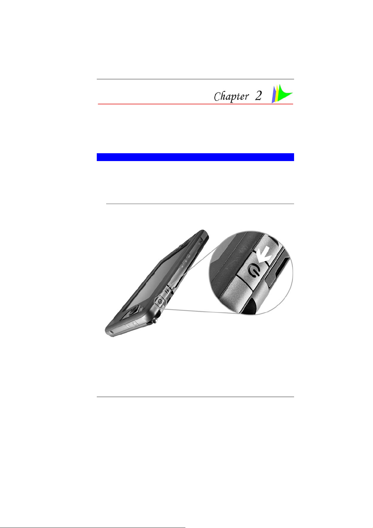
POWERING UP THE TABLET PC
At the top of the Tablet PC, locate on the power button and press
for a few seconds to power up the system.
11
Page 24
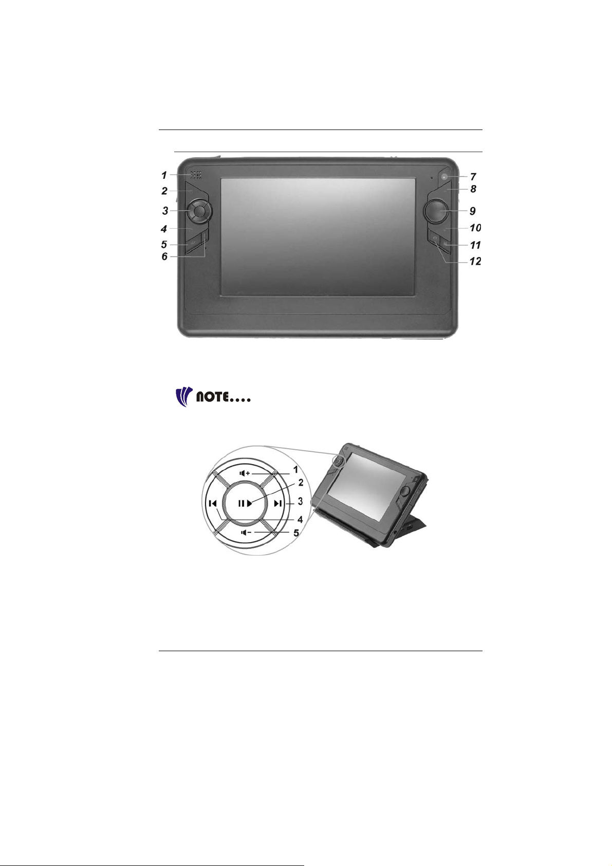
FRONT SIDE FEATURES
Speaker
11..
Stick Pointer Button (Mouse Left Button)
22..
Media Player Adjustment Buttons
33..
Use these buttons for adjustment when you
are playing any audio or video files using the Windows’ Media
Player.
12
Volume Up Button – Press this button to increase the
n
volume.
Play/Pause Button – Press this button to start
o
playing/pause any file.
Next Track Button – Press this button to start the next
p
track
Page 25

Previous Track Button – Press this button to start the
q
previous track.
Volume Down Button – Press this button to decrease the
r
volume.
Stick Point Button (Mouse Right Button)
44..
Internet Explorer Button
55..
Tool Button
66..
Built-In Camera
77..
Page Up Button
88..
Stick Point
99..
Page Down Button
1100..
Media Player Button
1111..
Camera Button
1122..
TOP SIDE FEATURES
Power Button
11..
CardReader
22..
Be sure the face of the card must be facing
down when inserting without using the stand or bottom side facing
you when inserting using the stand.
Lock Switch
33..
13
Page 26
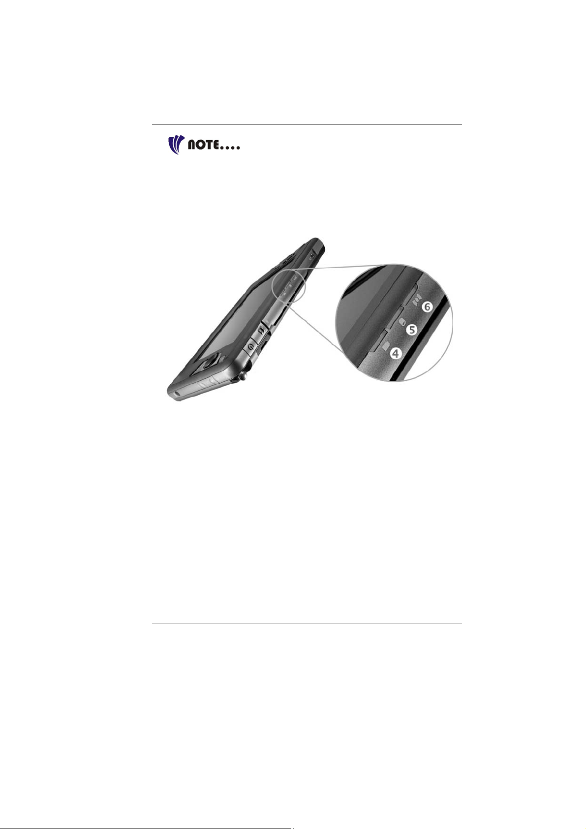
You will not be able to open the system if this
button is in lock position. To unlock, slide it back to the direction of
the power button.
LED Indicator
Battery Charge LED Indicator
44..
HDD LED Indicator
55..
Wireless LED Indicator
66..
14
Microphone Jack
77..
Earphone Jack
88..
USB 2.0 Port
99..
Page 27
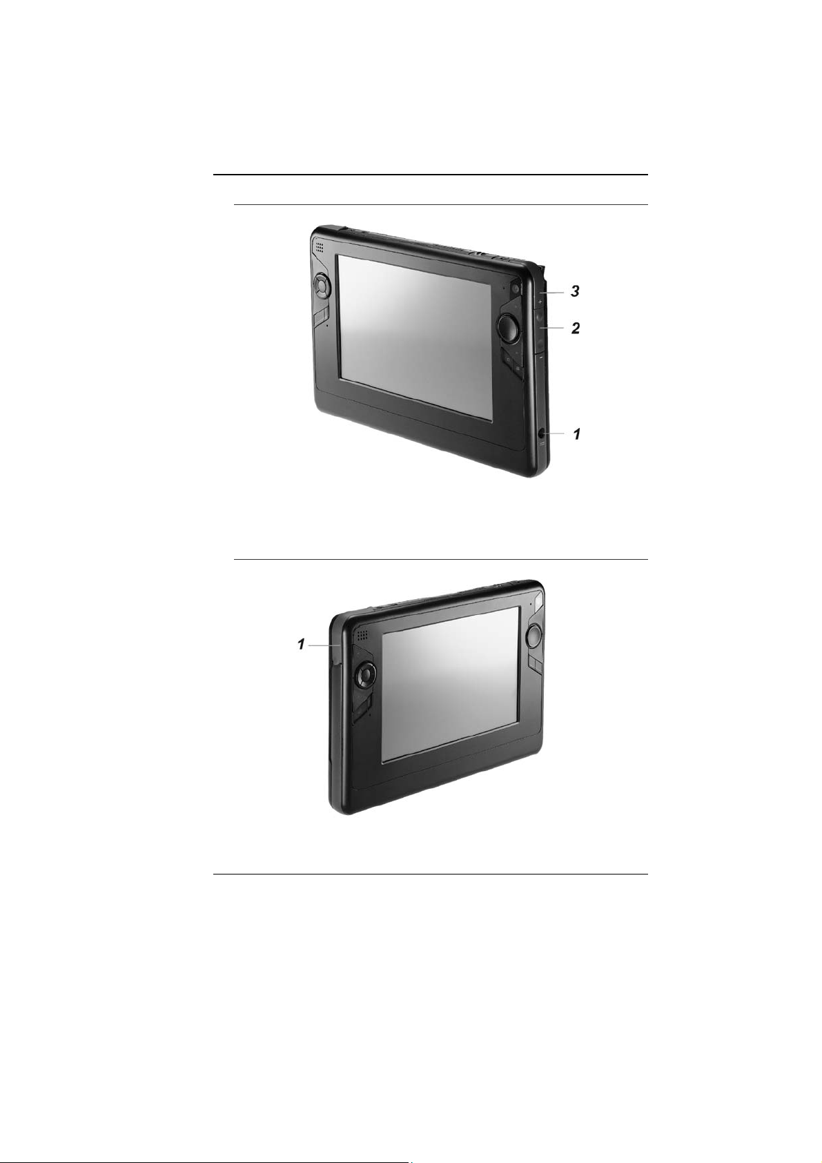
RIGHT SIDE FEATURES
DC-In Connector
11..
Brightness Control Buttons
22..
Pen Holder
33..
LEFT SIDE FEATURES
USB 2.0 Port
11..
15
Page 28
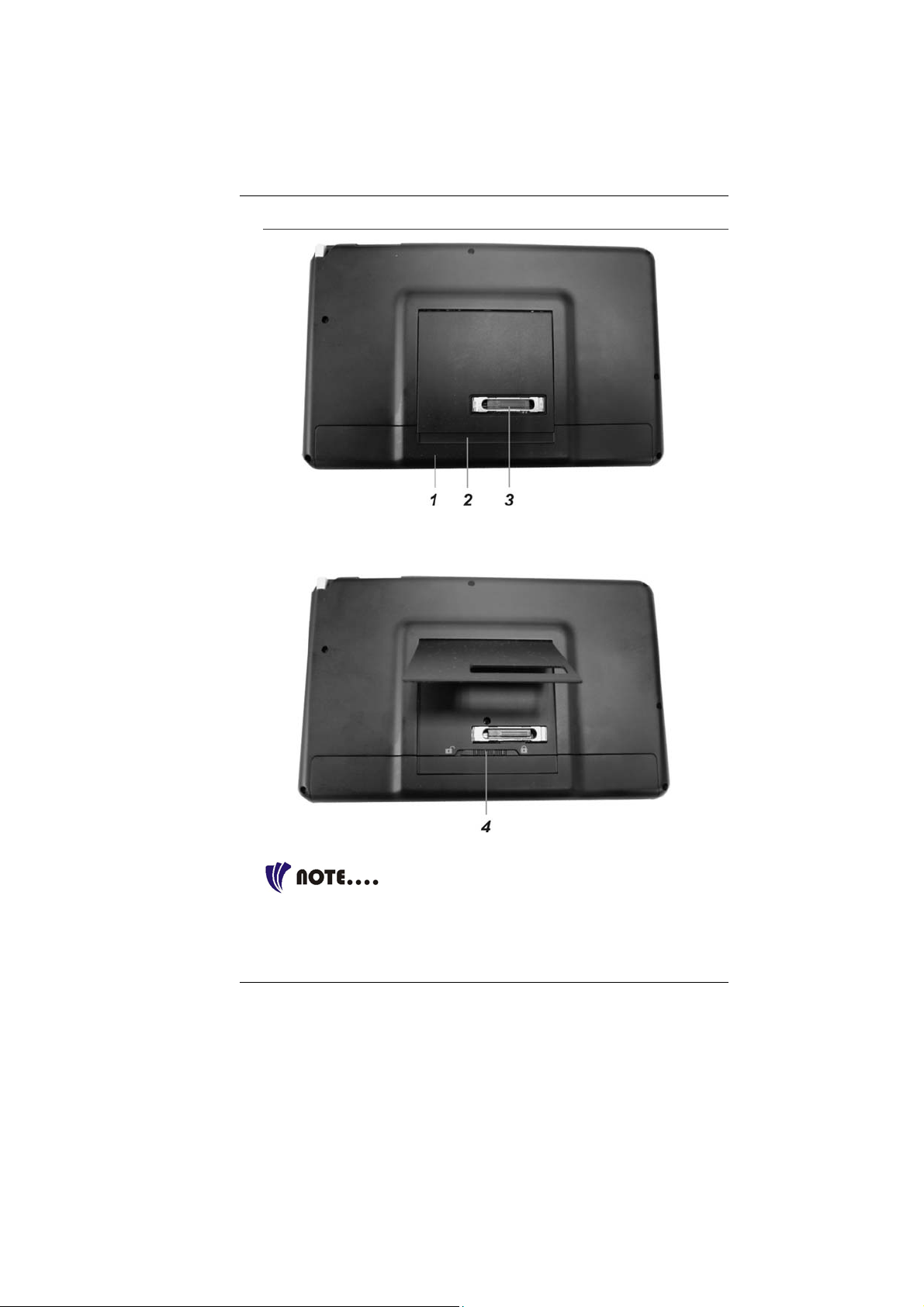
THE BACK SIDE FEATURES
Battery Compartment
11..
Tablet’s Stand
22..
System Inferface Connector
33..
Battery Release Latch
44..
Slide the latch to right direction will lock and
to left direction will unlock the battery compartment cover.
16
Page 29

CONTROL BUTTONS
A
PPLICATION BUTTONS
Icon KEYS FUNCTION(S)
Internet Button
Tool Button
Multimedia Button Press this button to execute the Media
Camera Button Press this button to turn ON the camera
Press this button to launch the Internet
Explorer.
Press this button to execute the System
Management Master function.
Player function
function.
NAVIGATION BUTTONS
This buttons consists of Page Up and Page Down
segments.
When you press the Page Up c, you will scroll up
one page.
When you press the Page Down d, you will scroll
down one page.
TOUCHPAD BUTTONS
This buttons consists of the equivalent function when
you are using the mouse.
When you press the
double clicking function you normally use on a
conventional mouse.
When you press the button, this will execute other
list of functions.
button, this will execute the
STATUS DISPLAY
Icons appear at the bottom of each individual system status LEDs
display indicating the present status of system.
Icon Keys LED
Status
Power Blue Press this button once to power on
or enter the suspend/resume mode
(blinking LED).
Remarks
17
Page 30

Off Press this button for more than 4
seconds to power off the system.
Battery
Wireless Green The system is in wireless status
HDD
Green Battery capacity 10~100%
Orange Battery charging status
Green Displayed when hard disk drive is
accessed
Off Hard disk is not being accessed
SYSTEM MANAGEMENT MASTER FUNCTION
The System Management Master function provides you to enable
some of the most common functions normally found on any other
related products in the market. It also acts as a power saving
scheme for your system.
From the Touchpad buttons as mentioned in the preceding topic,
press the
button to open/close this display.
` 90° Rotation function - Click this function will rotate the
screen at 90 degree counterclockwise direction as shown in
the illustration enabling you to use the system whether in
portrait or landscape position.
This function is only applicable when the
resolution is 800 x 480.
` Bluetooth function – execute the Bluetooth function of your
system. Default: On/Off.
18
Page 31

` Wireless function – execute the wireless function of your
system. Default: On/Off.
` Camera function – execute the built-in camera function of
your system. Default: On/Off
` Resolution – select these items converting the screen
resolution to 800x480, 800x600, 1024x600, and 1024x768.
19
Page 32

20
Page 33

Getting Started
CONNECTING TO A POWER SOURCE
C
ONNECTING THE AC ADAPTER
A universal AC adapter is provided to supply your computer with
power and also charge the computer’s battery pack. The adapter’s
AC input voltage can range anywhere from 100 to 240 volts,
covering the standard voltages available in almost every country.
The power cord for the AC adapter requires a three-hole grounded
AC outlet. To connect the computer to an external power source:
Do not use inferior extension cords as this
may result in damage to your computer. The computer comes w ith
its own AC adapter. Do not use a different adapter to power the
computer and other electrical devices.
21
Page 34

Whenever possible, keep the AC adapter plugged into the
computer and an electrical outlet to recharge the battery.
Never turn off or reset your comptuer while
the hard disk is in use; doing so can result in loss or destruction of
your data. Always wait at least 5 seconds after turning off your
computer before turning it back on; turning the power on and off in
rapid succession can damage the computer’s electrical circu itry.
TURNING ON YOUR COMPUTER
Turn on your computer by pressing the power button. Hold the
button down for a second or two and release. The Power-On Self
Test (POST) runs automatically.
After the POST is completed, the computer reads the operating
system from the hard disk drive into computer memory (this is
commonly referred to as “booting” a computer). If your OS
(Operating System such as Windows XP…. etc) is installed, it
should start automatically.
To turn the computer off, save your work and close all open
applications, click on Start, then Shu
down the computer and click "Y
t Down and select Shut
es" or press the power button for
4-6 seconds.
OPERATING ON BATTERY POWER
Your computer comes with a rechargeable battery pack that lets
you operate the computer without an external power source.
When the battery pack is fully charged, you can operate the
computer under the following conditions:
` The battery pack initially has a full charge.
` No peripheral devices are installed.
Only use batteries that are approved by an
authorized dealer. All batteries are not the same and therefore
should not be treated as such. Using the wrong battery could cause
serious damage to your computer and yourself through toxic
emissions.
Inserting and Removing the Battery Pack
The battery pack should already be inserted in your computer
when you unpack it. If not inserted, follow these directions:
22
Page 35

To remove the battery pack:
23
Page 36

Charging the Battery Pack
The installed battery pack charges automatically any time the
computer is connected to the AC adapter and an external power
source. It is a good idea to occasionally discharge the battery pack
fully to preserve its operating performance.
24
Page 37

Using the Computer
THE STICK POINTER
The Stick Pointer is a round electronic panel located at the right of
the LCD panel. You can use the buttons at the left that act as left
and right buttons of an ordinary mouse.
Stick Pointer Precautions
The Stick Pointer is a pressure sensitive device. Please take note
of the following precautions.
` Make sure the Stick Pointer does not come into contact with
dirt, liquids or grease.
` Do not touch the Stick Pointer if your fingers are dirty.
` Do not rest heavy objects on the Stick Pointer or the Stick
Pointer buttons.
You can use the Stick Pointer with Microsoft Windows as well as
non-Windows applications.
POWER SAVING MODES
This section contains information on the computer’s power system,
including the AC Adapter, the battery system, recharging the
battery, and tips for conserving battery power.
25
Page 38

The power system is comprised of two parts, the AC Adapter and
the battery system. The AC Adapter converts AC power from a wall
outlet to the DC power required by the computer.
THE BATTERY POWER SYSTEM
Before using the computer on battery power for the first time,
check the battery status icon on the Windows Toolbar to make
sure the battery is fully charged.
See Battery Status later in this section for a description and
explanation of the Windows Battery icon. Charging the battery
takes about 3 hours to charge when the system is in off state. If
possible, always charge the battery completely.
If you use the battery so frequently that it
exceed more than 20 times by fully discharging/charging in a single
month alone, we recommend you to perform the “Battery
Calibration” process every 3 months to maintain the battery life.
Please refer to the topic on “Battery Calibration” describing how to
calibrate your system battery discussed on the latter part of this
chapter.
If you discover the battery life is getting shorter, please perform the
“Battery Calibration” process immediately.
REMOVING THE BATTERY PACK
To remove the battery pack from its compartment, please refer to
Chapter 3, Inserting and Removing the Battery Pack.
Preparing the Battery Pack for Use
Before using the battery pack for the first time, the Smart Battery
IC within the battery pack should be calibrated in order to get
accurate reporting of remaining battery life status.
To calibrate the battery pack follows the instructions below:
1. Insert the battery into the battery compartment and turn on the
computer. If the battery is completely without power go to the
next step. Otherwise, let the battery run down until the battery
low-low warning beeps are heard.
The system will automatically enter Suspend mode.
2. Turn the computer off. Connect the AC adapter and let the
battery fully recharge. When the battery charge indicator turns
off, the battery is fully charged.
26
Page 39

3. Turn On the computer, let the battery run down until the
battery is in low-low state and you hear a warning beeps. The
system will automatically enter the Suspend mode. You can
now connect the AC adapter.
4. The battery pack is now calibrated properly.
In general, using the battery until the low-low battery-warning
indicator appears and fully recharges the battery each time (full
discharge/charge cycle) will ensure the accurate reporting of the
battery gauge status.
Automatic Battery Pack Charging Function
You can automatically charge the battery pack by using the AC
Adapter. The charge time is about three hours when the computer
power is turned off. The following table summarizes the charging
modes:
Charge Mode Charge Time
Fast 3 hours with the system off or in Suspend mode.
The temperature must be 25°C or below room
temperature.
Pre-Charge A pre-charge is supplied to the Li-Ion battery pack.
Battery Status
Windows XP has an applet in the Control Panel that will display an
icon in the Windows taskbar indicating when the computer is
running on battery power or is attached to the AC adapter.
This applet also displays a meter that indicates how much charge
is remaining in the battery.
Battery Low Warning
When the pack initially reaches the “Battery Low” state
approximately 10 ~ 15 minutes of the usable battery life is left.
You will hear an audible beep signal every 5 seconds alerting you
to the “Battery Low” status. When the battery power reaches the
“Battery Low Low” status the beeping sound will accelerate.
Your battery now has 1 ~ 2 minutes of battery charge remaining.
You must save your data or connect AC power immediately;
otherwise, you may lose your data.
Sound Meaning
Continuous
beeping every 5
seconds
Battery Low: Indicates that there is 7 to 10 minutes
charge remaining.
27
Page 40

Beeping
accelerates
Battery Low Low: Indicates that there is 1 to 2
minutes of battery charge remaining. Save your
work and turn off the computer, or connect the AC
adapter.
When there is only one minute of battery charge remaining, the
computer will suspend to the HDD and power off. You should
connect AC power and resume to save your work.
Small Battery for the Real Time Clock
There is a small built-in battery pack that supplies power to the
system in order to maintain certain system information while the
power is off. If the computer is left without a power source for long
period of time, this battery will be exhausted and system
information will be lost.
Danger of explosion if battery is incorrectly
replaced. Replace only with the same or equivalent type
recommended by the manufacturer. Dispose of used batteries
according to the manufacturer's instructions. Never remove the
battery pack while the power is on as this may result in data loss
when the system loses power.
BATTERY CALIBRATION
The purpose for this process is to provide a longer battery life for
your system battery pack.
1. Turn on the computer, when the text appears, press [Del] or
the [Delete] key until the system enters the BIOS Setup screen,
you may now make the necessary changes.
2. Press the Î arrow key until it reaches the “Exit” menu screen.
Again press the Ð arrow key and select the “Battery
Calibration” item.
Press the [Enter] key and disconnect the AC adapter then
press the [Y] key until you hear continuous battery low-low
warning beeping sounds.
The system will be fully discharge and shutdown completely.
3. Connect the AC adapter and let the battery fully recharge. The
“Battery Charge LED” of the computer will light indicating it is
in charging status.
4. When the battery charge LED turns off will indicate the system
is fully charged.
5. Repeat step 1 to 4 once again.
6. The battery is now fully calibrated.
28
Page 41

RESETTING THE SYSTEM
After installing a software application package, you may be
prompted to reset the system to load the changed operating
environment. To reset the system, or “reboot,” press the
[Ctrl]+[Alt]+[Delete] button. This is known as “warm boot.” This
key combination acts as “software” reset switch when you
encounter hardware or software problems, which lock up the
computer.
ADJUSTING THE BRIGHTNESS
To adjust the brightness on the LCD screen, use the brightness
adjustment button located at the right sides of the system. Press
on the + knob to increase and – knob to decrease the brightness of
your LCD display.
USING THE PEN
You can use the pen to generate, to select items, and to navigate
through programs on the Tablet PC.
` Hold the pen as if you were writing
with a standard pen.
` The pen interacts with the computer
whenever the tip of the pen
touches the screen.
Programs that support handwriting
recognition also allow you to write
characters directly on the screen with the
pen. You can also use the pen as a drawing
tool.
29
Page 42

The pen is a sophisticated, high-quality electronic instrument that
can be damaged if used improperly. Things to follow to protect
your pen:
` Do not gesture with the pen, use it as a pointer, or tap it on
surfaces other than the Tablet PC screen.
` Do not try to store the pen with the tip down (as you would
normally do with a pen) that it might distort the internal
mechanism. To avoid any damage to the pen, store it only in
the pen holder when you are not using it.
WRITING AREA
Any area where you can enter handwriting to be converted into
typed text and inserted in a program. Input Panel contains two
writing areas, one on the writing pad and one on the character pad.
USING THE SCREEN KEYBOARD
Press on the “Keyboard” icon to display the screen keyboard on
your screen in case you would make an input to the system.
ON SCREEN KEYBOARD
The keyboard in Input Panel. Use it the same way that you would
use a standard keyboard.
WRITING PAD
A pad that you use to write text that is converted into typed text.
You write on lines in the writing pad the same way you write on a
lined piece of paper.
30
Page 43

CHARACTER PAD
A pad that converts your handwriting into text so that it can be
inserted into a program. You use the character pad to write on
letter at a time.
To enhance your writing capability, click on the “Num” and “Sym” to
display the on screen “Numeric” and “Symbol” keys respectively.
To make a selection on how it will be proper for the on-screen
keyboard to illustrate on your display, a special function is design
to solve all these problem.
Press on this icon to display the selection item for the
on-screen keyboard to appear on the screen.
Speech
By using a microphone, you can speak to your tablet computer
either to dictate or give commands.
Dock at Top of Screen
Let the on-screen keyboard to appear at the top of the screen.
Dock at Bottom of Screen
Let the on-screen keyboard to appear at the bottom of the screen.
Undock
Closed down the on-screen keyboard.
Options
` General – Provides you which action to be taken when
opening the Input Panel
31
Page 44

` Settings – Lets you select the option on how the insert button
to appear on your display
` Character Pad – Lets you select on the ink thickness of the
text and the spaces between them
` Writing Pad – Lets you select on the thickness of the text and
the spaces between every written lines
` Speech – Sounds provide useful validation during speech
recognition
TOUCHKIT UTILITY
After you have restarted Windows, select and double click the
“Touchkit” icon on the desktop. Touchkit utility provides some
useful function for adjustment where you can easily manage all the
controllers through the Touchkit utility.
Some questions on how to use the Touchkit
application; please refer to the online “Help” for detail.
PEN CALIBRATION
If your cursor pointer does not function well, you can select the
“Calibration” tap “4 pts Cal” button or “Advanced” tap -> 25 pts
Cal” button and click it to correct point locations.
32
Page 45

CALIBRATION < 4 PTS CAL >
Correct 4 point locations on the screen with the panel, screen
displays as follows: Touch the blinking symbol on panel until it
stops blinking.
ADVANCED < 25 PTS CAL >
25 point calibration is more accurate for touch sensor. In general
case, it does not need to do 25 points calibration other than bad
linearity sensor.
33
Page 46

USING THE WINDOWS
H
ELP WINDOWS
For Windows XP help, click Start ÎHelp and Support icon will
open the dialog box.
DESKTOP
Desktop may vary differently on the software installed in your
computer with different or additional shortcuts.
34
Page 47

Recycle Bin
Used for storing deleted files in case you want to recover and save
it in your system. The files will only be deleted from the Recycle
Bin permanently only if you empty it by right clicking your mouse
and select the “Empty Recycle Bin”.
Start Button
Allows easy access to all
Windows programs.
The Start menu allows
you to adapt and show
the programs used most
frequently. If you wish to
keep an item, right click
the item and click Pin to
Start menu.
Log Off will enable the
current user to log off and
allows a new user to log
on.
Turn Off Computer
allows you to shut down,
restart, and Stand by
modes for power saving
purposes.
Taskbar
When you open a program, its icon is displayed at the taskbar for
you to conveniently move between programs by clicking the
relevant button.
To add or remove toolbars from the taskbar: right click an empty
spot on the taskbar, select Toolbars Î choose the toolbar you
want to a d d.
Notification
The icons that appear here are for quick access to some programs
and computer functions that you frequently used. For you to see
the hidden icons, simply click the
icon.
To prevent Windows XP from hiding icons:
From an empty spot on the Taskbar, right click your mouse and
select the Properties, remove the checked mark on the Hide
inactive icons.
35
Page 48

CONTROL PANEL
It is in this area that you can change how Windows looks and
works. Click Start Î Control Panel dialog box. There are two
interfaces – Classic View or Category View.
36
Page 49

Desktop Operation
Your computer is capable of providing you with efficient and
productive mobile computing, it also has the speed and capacity to
service as a desktop system.
This chapter discusses those functions of your computer that are
typical of desktop systems.
AUDIO
T
HE MULTIMEDIA SOUND SYSTEM
The computer’s built-in audio capabilities allow you to take
advantage of a wide range of education and entertainment
multimedia software. The computer is equipped with an internal
stereo speakers, a microphone, and output audio ports for external
audio units.
An external microphone can be connected to the microphone jack.
External speakers or headphones can be connected to the
computer’s audio-out jack.
` External audio devices can be connected to the Line in jack.
All audio features are software controlled.
AUDIO VOLUME CONTROL
To control the volume of your computer, use the volume control on
the Windows. (Click on the Start Î Control Panel Î Sounds,
Speech, and Audio Devices Î Sounds and Audio Devices Î put
a check mark on the “Place volume icon in the taskbar” in the
“Sounds and Audio Devices Properties” window display and click
the “OK” button.
37
Page 50

AUDIO SOFTWARE
Your computer comes equipped with an integrated sound system
capable of providing you with quality audio sound through the builtin speakers or through external speakers connected via the system
ports.
38
Page 51

SOUND RECORDING
Your system allows you to record sounds and store them as files
using the microphone via the microphone jack of the computer.
Check the Windows Help and Support Center in Windows for
information on using the various elements in sound recording.
For a high-quality sound, click on the
"Volume Control" at the lower right end of your screen. From the
Volume Control windows, click on the "Advanced" tab, click and
select the "Microphone Boost" item.
PLAYING SOUND FILES
Your computer can play audio files stored in MIDI, WAVE or MP3
file format. Check the Help and Support Center in Windows for
information on the functions of the Media Player.
EXTERNAL SPEAKERS AND MICROPHONE
The sound system is capable in providing high-quality sound to
external speakers and receiving and processing sounds from an
external microphone or external sound source.
39
Page 52

40
Page 53

Internet Connection (Optional)
There are numerous ways to connect to the Internet. This may vary
from the user’s working environment as well as system
specifications.
` Using a wired LAN
` Using a wireless LAN (Optional)
USING A WIRED LAN FOR CONNECTION TO INTERNET
For you connect to the Internet, a wired LAN environment normally
uses the company’s LAN or a broadband modem.
1. Use the network (LAN) cable to connect to the LAN port of the
system.
2. Select on “My Network Places” and click on the “View Network
Connection” in the “Control Panel” window.
3. In the “Network Tasks” window, use your mouse pointer to
click on the “Local Area Connection”.
4. Select “Properties” from the popup menu that appears
41
Page 54

5. In the “This connection uses the following items” field, select
“Internet Protocol (TCP/IP), and click “Properties”.
42
Page 55

6. Enter the system’s IP and DNS server addresses on the
General tab of the “Internet Protocol (TCP/IP) Properties”
window. If DHCP is used, click “Obtain an IP address
automatically” and “Obtain DNS server address automatically”
on the General tab.
43
Page 56

7. After all the all the information are correctly entered in the
“Internet Protocol (TCP/IP) Properties” window, click “OK” to
finish.
USING BOTH DHCP AND STATIC IP FOR CONNECTION TO
INTERNET
When you are alternatively using networks with either DHCP or
static IP addressing, you can use alternative settings that enable
simultaneous configurations of DHCP and static IP to use both of
the network connects without reconfiguring.
1. Follow the steps mentioned when you are using wired LAN
connection from 1 to 7.
2. Click on the “User configured” and enter the appropriate
values in the “Alternate Configuration” tab.
44
Page 57

3. When you have completed the entire configuration, click “OK”.
45
Page 58

USING WIRELESS LAN NETWORK FOR CONNECTION TO INTERNET
(MICROSOFT’S SERVICE PACK 2) (OPTIONAL)
BLUETOOTH CONNECTION
Bluetooth is a developing, world wide, open, short-range radio
specification focused on communication between the Internet and
Net devices, plus it defines communication protocols between
devices and computers.
It connect wirelessly to your world: In home, at work, in motion and
at play.
Access the internet or your e-mail account from anywhere, anytime.
Fast downloads.
46
Page 59

Press on the Bluetooth icon to connect other devices that has
this application.
47
Page 60

48
Page 61

Running BIOS Setup
The BIOS (Basic Input and Output System) Setup program is a
menu driven utility that enables you to make changes to the
system configuration and tailor your system to reflect installed
hardware or alter system performance. When the computer is
turned back on, the system is configured with the values stored in
CMOS. With easy-to-use menus, you can configure such items as:
` Hard drives and peripherals
` Boot up Drive Sequence
` Password protection
` Power Management Features
The settings made in the BIOS Setup program intimately affect
how the computer performs.
NAVIGATING THROUGH BIOS SETUP
The Setup program has been designed to make it as easy to use
as possible. If you accidentally make a setting and don’t know
which one to switch back to, the Setup program has a hot key that
allows you to return to the previous value.
ACCESSING THE BIOS SETUP PROGRAM
To access the BIOS Setup program, press the DEL key after the
computer has run through its POST.
ITEM SPECIFIC HELP
On the right side of the Setup screen is an area labeled Item
Specific Help. This area will list navigation key shortcuts and
information that is specific for the item that you are currently editing.
49
Page 62

THE MENU BAR
The top of the screen has a menu bar with the following selections:
Main - Use this menu to make changes to the basic system
configuration.
Advanced - Use this menu to enable and make changes to the
advanced features available on your system.
Security - Use this menu to set a password. The password allows
bootup and controls access to the BIOS setup menu.
Boot - Use this menu to configure the default system device used
to locate and load the Operating System and for booting up the
computer.
Exit - Use this menu to exit the current menu or specify how to exit
the Setup program.
To access the menu bar items, press the right or left arrow key on
the keyboard until the desired item is highlighted.
THE LEGEND BAR
At the bottom of the Setup screen you will notice a legend bar. The
keys in the legend bar allow you to navigate through the various
setup menus. The following table lists the keys found in the legend
bar with their corresponding alternates and functions.
Legend
Key
F1 Displays the General Help window. It can
Esc Jumps to the Exit menu or returns to the
←
→
↑ or ↓
Tab Enter Moves the cursor to the next position
Minus
key (
-)
Alternate
Key
be enabled from anywhere in the BIOS.
Main menu from a submenu.
Selects the menu item to the left.
Selects the menu item to the right.
Keypad
arrow keys
Scrolls backward through the values for the
Moves the cursor up and down between
fields.
available in the field.
highlighted field.
Function
50
Page 63

Legend
Key
Plus key
(+)
Home PgUp Moves the cursor to the field at the top of the
End PgDn Moves the cursor to the field at the bottom of
F9 Sets the parameters for the current menu to
F10 Save and Exit.
Enter Will select a sub menu or show a range of
Alternate
Key
Scrolls forward through the values for the
highlighted field.
window.
the window.
their default values.
options for a field.
Function
LAUNCHING SUBMENUS
Note that a right pointer symbol X appears to the left of certain
fields. This pointer indicates that a submenu can be launched from
this field. A submenu contains additional options for a field
parameter. To call up a submenu, simply move the cursor to
highlight the field and press the [Enter] key. Use the [Esc] key to
return to the Main menu.
GENERAL HELP
In addition to the Item Specific Help window, the BIOS Setup
program also provides a General Help screen can be called up
from any menu by simply pressing [F1]. Use the [PgUp] and [PgDn]
keys or the up and down arrow keys (↑↓) to scroll through the
entire help document.
Press the Home key to display the first page, press End to go to
the last page. To exit the help window, press the [Enter] or the
[Esc] key.
Save Changes and Exit the Setup Program
Refer to the Exit menu section of this chapter for detailed
information on saving changes and exiting the setup program.
51
Page 64

THE MAIN MENU
When the Setup program is accessed, the following screen
appears:
52
Page 65

THE ADVANCED MENU
Selecting Advanced from the menu bar displays the Advanced
menu:
53
Page 66

THE SECURITY MENU
The computer’s advanced system of security allows you to set a
password to prevent unauthorized access to system resources,
data, and the BIOS Setup Program.
54
Page 67

THE BOOT MENU
The Boot menu allows the user to specify the order in which the
computer is to check for a device to boot the system. You can also
configure the way that the system will boot up.
To make changes, select Boot from the menu bar. The following
screen appears:
55
Page 68

THE EXIT MENU
Once you have made all of your selections from the various menus
in the Setup program, you should save your changes and exit
Setup. Select Exit from the menu bar to display the following menu:
56
Page 69

VGA Utilities
VGA UTILITIES
After you have restarted Windows, open the “Control Panel” and
double click on the “Display” icon. From the “Display Properties”
window, select the “Settings” tab and click on the “Advanced” tab
to enter the “Digital Flat Panel (1024x768) on Mobile Intel (R)
915GM/GMS,910GM" window.
57
Page 70

INTEL (R) GRAPHICS MEDIA ACCELERATOR DRIVER FOR
MOBILE
58
Page 71

59
Page 72

60
Page 73

Video Conferencing (Option)
This application offers video conferencing capabilities to work and
communicate in real-time with one or more participants through
streaming video, from any location. You can click on the icon on
the Windows screen display to run the capture application.
APPLICATION
Use the hot key of [Fn] + [F6] to capture the
image that appear on your application’s screen. You are allow ed to
capture the image for a number of times until you save it by
selecting the “Set Capture File…” in the “File” menu.
61
Page 74

USING COMMANDS AND BUTTONS
The File Menu Commands and Buttons
` Set Capture File - Set
to save directory and
video file name.
` Exit - Exit the
application.
The Device Menu Commands and Buttons
This set the size of the window screen of your capture application
62
Page 75

The Options Menu Commands
` Preview - Set preview in screen
or not.
` Video Capture Filter - Set
Properties.
` Video Capture Pin - settings of stream format.
You can set the corresponding feature for Environment, Frequency,
Rotation and Extension of your captured image file.
¾ Brightness/Contrast/Hue/Saturation/
Sharpness/Gamma/White Balance/Backlight Comp
- To adjust video settings and show value.
¾ Default - Reset all settings in this page to default.
63
Page 76

¾ Exposure - De-select the check mark on the box if
you want to change the value.
64
¾ Frame Rate - This function is to set video frame rate.
If your utility rate of CPU is too high, you can choose
the low frame rate to reduce the CPU’s utility rate.
¾ Output Size - Change the output size.
Page 77

Capture Menu Commands and Buttons
` Start Capture - start
capture video
stream.
` Stop Capture - stop
capture video
stream.
` Set Frame Rate - set frame rate while capturing a video.
` Set Time Limit - set time limit of capture stream.
65
Page 78

66
Page 79

Troubleshooting
This chapter describes locating and solving problems that you may
encounter while using your computer.
CHECKING CABLES AN D CONNECTIONS
Start by performing a careful visual inspection of the exterior of the
computer. If no LEDs are illuminated, make sure that your
computer and its peripherals are getting power and communicating
with each other properly.
To check the power cables, and connections:
1. If you have been using battery power, connect the computer to
an external power source and make sure that the battery has
a charge.
2. If you are using the computer with the AC adapter, check the
power outlet, the power cord, and any power switches that
may affect your computer.
3. Check the wall outlet or power strip with an item that you know
is functioning properly. A lamp or radio is a convenient item for
checking the power. You may also need to check the fuses
and breakers in your electric box.
4. If the outlet is controlled by a wall switch, make sure that the
switch is on.
5. If the outlet is controlled by a dimmer switch, use a different
outlet.
6. If your computer is plugged into a power strip with an On/Off
switch, make sure the switch is on.
7. With the computer’s power switched off, check all cable
connections. If the computer is connected to any peripheral
devices, look for loose or disconnected cables.
67
Page 80

If the computer is too close to a wall, a cable connection may be
loose or the cables may be crimped.
Do not substitute cables for different devices
(other than the manufacturer recommended cables) even if they look
exactly alike. The wiring inside the cable may be different.
8. When you are certain that you have power available and all
connections are good, turn the computer on again. If the
computer still does not start, you may have a hardware
problem.
GENERAL PROBLEMS
A few common hardware problems and suggested solutions are
presented in the table below:
SYSTEM NOT RESUMING OPERATION
If the system will not resume operation after system operation has
been suspended, check the following possible causes:
The battery may either be defective, or discharge to a critically low
level. To correct this problem, connect an external power supply
such as AC adapter.
DISPLAY SCREEN IS BLANK OR DIFFICULT TO READ
If the system is blank or unreadable, please confirm the system is
running (this can be seen on the Power icon if it is lit).
` The brightness control may be set too low, change the
brightness by using on the brightness control at the right side
of the system.
` The video timeout may have expired, tap on the display
screen to reactivate the display.
TABLET PC IS NOT RESPONDING TO THE PEN
If the Tablet PC does not respond to the pen, connect an external
keyboard to the system to see if it responds to keyboard
commands. If the system doesn’t respond to a keyboard, the
application or system may have crashed, and it may be necessary
to reboot the system. If the system responds to a keyboard but not
to a pen, contact your local dealer for further assistance.
68
Page 81

THE TABLET PC CAN NOT POWER ON
Check on the Lock key located right beside the Power button if it is
in lock position.
THE CURSOR NOT IN POSITION WHILE USING THE ORDINARY PEN
Change the settings in the touchkit settings window. Select
TouchKit program>4 pts Cal to calibrated.
THE COMPUTER IS UNABLE TO CONNECT TO THE INTERNET.
Account for Internet service provider (ISP) is not properly
configured. Ask for your ISP assistance.
NO SOUND ON THE EXTERNAL SPEAKERS OR HEADPHONES.
Connected to the wrong jack. Change to the correct jack.
BEEPING SOUND.
Connect the computer to an external power source immediately.
IF THE CURSOR IS NOT IN POSITION WITH THE TOUCH PEN
Please make sure you have made the linearization with the
touchkit utility. Please refer to Chapter 4 on the topic of calibration
to correct in aligning the cursor with the pen.
CONTACTING YOUR DEALER
If you still have a problem after reading the preceding sections, the
next step is to contact your dealer. Your dealer can determine if
the problem is something that requires the computer to be taken to
the shop. Before you call your dealer, however, prepare the
following information:
` How is your computer configured? Your dealer needs to know
what peripheral devices you are using.
` What messages, if any, are on the screen?
` What software were you running at the time?
` What have you done already to try to solve the problem? If
you have overlooked a step, your dealer may be able to solve
the problem over the phone.
69
Page 82

70
Page 83

Docking Station (Optional)
The Docking Station is designed to give your computer the
expandability and connectivity of a desktop computer, without
sacrificing convenience.
In addition, the Docking Station also has a DC IN connector.
FEATURES
RONT SIDE FEATURE
F
Power LED
11..
LAN Indicator
22..
Docking Connector
33..
71
Page 84

LEFT SIDE FEATURE
USB Port
11..
USB Port
22..
DOCKING RIGHT SIDE FEATURE
TV/CRT Toggle Button
11..
Press this button to toggle between the LCD and CRT display.
When the computer is inserted into the
docking station, you are able to drag the LCD graphic into either the
TV or CRT using this hot key combination if either of these tw o is
connected into the docking station.
72
Page 85

USB Port
22..
DOCKING REAR SIDE FEATURE
1. USB Port
2. LAN Connector
3. External CRT Port
4. S-Video Port
5. DC-IN Connector
73
Page 86

CONNECTING THE TABLET PC
74
Page 87

COMPUTER INSERTED INTO THE DOCKING STATION
When the computer is inserted into the docking station, there are
certain notices that you will have to be aware of.
` Battery mode: working on this mode will disable the function
of the button, ports and connectors on the docking station.
` AC mode: when the AC adapter is connected on the docking
station will enable the function of the button, ports and
connectors on the docking station.
75
Page 88

76
Page 89

Specification
DETAILED SPECIFICATIONS
Processor
` Value - Intel® Celeron® M ULV 900MHZ, L2 cache=512KB on
die, FSB=400MHZ
` Premium - Intel® Pentium® M ULV 1GHZ, L2 cache=2MB on
die, FSB=400MHZ
Operating System Compliance
` Microsoft
` Microsoft
Core Logic
` Intel 915GMS+ ICH6-M
Memory
` Value - DDR2 400, SO-DIMM SDRAM module, 256MB
` Premium - DDR2 400, SO-DIMM SDRAM module, 512MB
LCD Display
` 7" WVGA (800x480) TFT LCD
Video & Graphics
` Integrated graphic controller: Intel GMA900, SMA up to 128MB
DDR2 SDRAM
Hard Drive
` Value - 1.8" 30GB, 4200rpm
` Premium - 1.8" 60GB, 4200rpm
®
Windows® XP Tablet Edition
®
Windows® XP Home/ Professional Edition
77
Page 90

Card Reader
` 3-in-1 card reader (Support SD/SDIO/MS/MMC)
Camera
` 1.3M pixel CMOS Camera
Pointing Device
` Touch screen with Stylus Pen, Synaptics pointing stick
Application Launch Key
` Camera, Movie, Internet, Tool Button
LED Status Indicator
` Power, HDD, Battery, WLAN
IO Ports
` USB 2.0x2 ,Audio in, Earphone, DC in, Docking connector
Docking (optional)
` USB 2.0x4 ,VGA-out, S-video out, Ethernet, DC-in
Audio
` HD 7.1 channel Audio, Built-in speaker and microphone
AC Adapter
` 65W
Battery
` 3 cell Li-ion battery pack 11.1V 2400mAh
BIOS
` AMI, Support PnP,
` Support PnP, password
Communication
` Bluetooth Module
` 802.11b/g WLAN card
Power Management
` ACPI 2.0 compliance
` Support Stand-by, Suspend to Disk, Suspend to RAM
Size
` 225.5x144x.23/25mm
Weight
` 830g
78
Page 91

Accessories
` Quick Guide, Support CD (Driver, Utility, Manual), AC Adapter,
Power Cord, Battery Pack
Remark
` Battery life will vary depending on your specific hardware and
software configuration
` Spec subject to change without notice
79
 Loading...