

Page 1

i
Page 2

Preface
Copyright 2011
All Rights Reserved.
The information in this document is subject to change without prior
notice in order to improve reliability, design and function and does
not represent a commitment on the part of the manufacturer.
In no event will the manufacturer be liable for direct, indirect,
special, incidental, or consequential damages arising out of the
use or inability to use the product or documentation, even if
advised of the possibility of such damages.
This document contains proprietary information protected by
copyright. All rights are reserved. No part of this manual may be
reproduced by any mechanical, electronic, or other means in any
form without prior written permission of the manufacturer.
Limitation of Liability
While reasonable efforts have been made to ensure the accuracy
of this manual, the manufacturer and distributor assume no liability
resulting from errors or omissions in this manual, or from the use of
the information contained herein.
Notice:
Changes or modifications not expressly approved by the party
responsible for compliance could void the user’s authority to
operate the equipment. Shielded interface cables and a nonshielded AC power cord must be used in order to comply with
emission limits.
This equipment is to be used with power supply:
90W
There is no internal power supply.
i
Page 3

Table of Content
EFORE YOU START ............................................................................... 2
B
LET YOUR COMPUTER ACCLIMATE ITSELF .............................................. 6
HEAT, COLD, HUMIDITY, AND GLARE .................................................... 7
SUITABLE PLACE TO WORK ................................................................... 7
INTRODUCTION........................................................................................ 9
LEFT VIEWS ...................................................................................... 12
RIGHT VIEW ...................................................................................... 13
GETTING STARTED ............................................................................... 16
CONNECTING THE AC ADAPTER ......................................................... 16
TO INSTALL THE BATTERY PACK: ........................................................ 18
TO REMOVE THE BATTERY PACK: ...................................................... 19
USING THE NOTEBOOK COMPUTER ....................................................... 21
LCD CARE ........................................................................................ 21
EXTERNAL CRT DISPLAY ................................................................... 21
TOUCHPAD PRECAUTIONS ................................................................. 22
DATA STORAGE AND RETRIEVAL ........................................................ 23
THE BATTERY POWER SYSTEM .......................................................... 23
PREPARING THE BATTERY PACK FOR USE (BATTERY CALIBRATION) .... 24
AUTOMATIC BATTERY PACK CHARGING FUNCTION .............................. 25
BATTERY STATUS .............................................................................. 25
BATTERY LOW WARNING ................................................................... 25
HELP WINDOWS ................................................................................ 27
DESKTOP .......................................................................................... 27
INTERNET CONNECTION ........................................................................ 32
RUNNING BIOS SETUP ......................................................................... 34
MAIN SETUP ..................................................................................... 36
INFO SETUP ...................................................................................... 37
ADVANCED ........................................................................................ 38
SECURITY SETUP .............................................................................. 38
BOOT SETUP ..................................................................................... 39
EXIT SETUP ...................................................................................... 39
ii
Page 4

SUPER POSH ...................................................................................... 41
ADVANCED PAGE .............................................................................. 44
OPTIMIZING WINDOWS SETTING: ........................................................ 51
HARD DISK MENU .............................................................................. 53
CPU ................................................................................................. 54
RAM: ............................................................................................... 54
WARNING: ......................................................................................... 55
SPECIFICATION ..................................................................................... 60
iii
Page 5

Page 6

1
Page 7

BBeeffoorree yyoouu SSttaarrtt
CCoonnvveennttiioonnss ooff TThhiiss MMaannuuaall
Use this manual will help you get the most from your notebook
computer.
If you are an experienced user of computers and/or
Microsoft’s Windows operating systems, you might find it
useful to read the Quick Start Guide that comes along with
your accessories.
If you are a less experienced user, you should get through
the manual carefully before using your system.
Whether or not you are an experienced user, you should consult
on the Troubleshooting Chapter if you encounter any problems
with your notebook.
EEMMCC CCllaassssiiffiiccaattiioonn
mmooddiiffiiccaattiioonnss nnoot
o
ffoorr cco
mmpplliiaannccee ccoouulldd vvooiidd tthhee uusseerr’’ss aauutthhoorriittyy ttoo ooppeerraatte
eeqquuiippmmeenntt..
This equipment has been tested and found to comply with the
limits for a Class B digital device, pursuant to part 15 of the FCC
rules. These limits are designed to provide reasonable protection
against harmful interference in a residential installation. This
equipment generates, uses and can radiate radio frequency
energy and, if not installed and used in accordance with the
instructions, may cause harmful interference to radio
communications. However, there is no guarantee that interference
will not occur in a particular installation. If this equipment does
cause harmful interference to radio or television reception, which
can be determined by turning the equipment off and on, the user is
encouraged to try to correct the interference by one or more of the
following measures:
Re-orient or relocate the receiving antenna.
Increase the separation between the equipment and receiver.
t eexxpprreessssllyy aapppprroovveedd bbyy tthhee ppaarrtt rreessppoonnssiibbllee
YYoouu aarree ccaauuttiioonneedd tthhaatt cchhaannggeess oorr
e tthhee
2
Page 8

Connect the equipment into an outlet on a circuit different
from that to which the receiver is connected.
Consult the dealer or an experienced radio/TV technician for
help.
SSaaffeettyy PPrreeccaauuttiioonnss
This section is designed to assist you in identifying potentially
unsafe conditions while working with this product. Required safety
features have been installed in the computer to protect you from
injury. However, you should use good judgment to identify potential
safety hazards:
1. Please read these safety instructions carefully.
2. Please keep this User's Manual for later reference.
3. Please disconnect this equipment from AC outlet before
cleaning. Don't use liquid or sprayed detergent for cleaning.
Use moisture sheet or cloth for cleaning.
4. For pluggable equipment, that the socket-outlet shall be
installed near the equipment and shall be easily accessible.
5. Please keep this equipment from humidity.
6. Lay this equipment on a reliable surface when installed. A
drop or fall could cause injury.
7. Make sure to use the right voltage for the power source when
connecting the equipment to the power outlet.
8. Place the power cord in such a way that people can not step
on it. Do not place anything on top of the power cord.
9. All cautions and warnings on the equipment should be noted.
10. If the equipment is not used for a long time, disconnect the
equipment from the main power outlet to avoid being
damaged by transient overvoltage.
11. Never pour any liquid into the opening, this could cause fire or
electrical shock.
12. Never open the equipment. For safety reason, the equipment
should only be opened by a qualified service personnel.
13. If on the following situations arises, get the equipment
checked by a service personnel:
a. The Power cord or plug is damaged.
b. Liquid has penetrated into the equipment.
c. The equipment has been exposed to moisture.
d. The equipment has not worked well or you cannot get it
work according to the user's manual.
e. The equipment has dropped and damaged.
f. If the equipment has obvious sign of breakage.
3
Page 9

14. Do not leave this equipment in an environment unconditioned,
storage temperature above 60C (140f), it may damage the
equipment.
15. The unit can be operated at an ambient temperature of max.
5C to 35C.
16. The sound pressure level at the operators position according
to IEC 704-1: 1982 is equal or less than 70 dB(A).
17. Power Cord Requirements
The power cord set used with the AC adaptor must meet the
requirements of the country where you use the AC adaptor,
whether it is 100-240 Vac. The following information explains
the requirements for power cord set selection.
The cord set must be approved for the country in
which it is used.
The appliance coupler must have a configuration for
mating with a CEE7/EN60320/IEC 320/NEMA/ JIS C
8303 appliance inlet.
A. For U.S. and Canada:
The cord set must be UL Listed and CSA Certified.
The minimum specifications for the flexible cord are
No. 18 AWG, (2) Type SPT-2, and (3) 2-conductor.
B. For Japan:
All components of the cord set must bear a “PSE”
mark and in accordance with the Japanese Dentori
Law.
The minimum specifications for the flexible cord
are .75m ㎡ conductors, (2) Type VCTR or VCTFK,
and (3) 2-conductor.
The cord set must have minimum rated current
capacity of 7 A.
The attachment plug must be a two-pole, grounded
type with a Japanese Industrial Standard C8303 (15
A, 125 VAC) configuration.
C. For Other Countries:
The cord set fittings must bear the certification mark
of the agency responsible for evaluation in a specific
country.
The flexible cord must be of a HAR (harmonized)
type H03VVH2-F.
4
Page 10

The cord set must have a current capacity of a least
2.5 Amperes and voltage rating of 125 or 250 Vac.
ddeessiiggnneedd ttoo uussee wwiitth
MMOODDEELL HH4422IIAAxx//HH4433IIAAxx ((xx==00~~99)) iiss
h tthhee ffoolllloowwiinngg AACC aaddaapptteerr mmooddeell oonnllyy..
Delta Electronic, Inc.
ADP-90SB-AB (90W, 2 pin)
Huntkey Electronic Co., LTD
HKA0901904/8D(90W, 2 pin)
18. When using your telephone equipment, basic safety
precautions should always be followed to reduce the risk of
fire, electric shock and injury to persons. These precautions
include the following:
Do not use this product near water, for example, near a
bathtub, washbowl, kitchen sink or laundry tub, in a wet
basement or near a swimming pool.
Avoid using a telephone (other than a cordless type)
during an electrical storm. There may be a remote risk
of electric shock from lightning.
Do not use the telephone to report a gas leak in the
vicinity of the leak.
Use only the power cord and batteries indicated in this
manual. Do not dispose of batteries in a fire. They may
explode. Check with local codes for possible special
instructions.
19. Do not use the AC adapter near open water or other liquids.
Never spill liquid into the AC adapter.
20. Danger of explosion if battery is incorrectly replaced. Replace
only with the same or equivalent type recommended by the
manufacturer. Dispose of used batteries according to the
manufacturer's instructions. Never remove the battery pack
while the power is on as this may result in data loss when the
system loses power.
21. The input receptacle is used as the main disconnecting device.
TThhiiss ppaarrtt iiss hhoott.. BBee ccaarreeffuull..
WWhheenn yyoouu sseeee tthhiiss ssyym
vveerryy hhoott..
22. Laser Warning: Laser Class I Product Caution - Invisible laser
radiation when open avoid exposure to beam.
The optical drive used with this computer is certified as a
mbbooll,, bbee ccaarreeffuull aass tthhiiss ssppoott mmaayy bbee
5
Page 11

Class1 laser device according to the U.S. Department of
Health and Human Services (DHHS) Radiation Performance
Standard and International Standards IEC 60825-1
(EN60825-1). The device is not considered harmful, but the
following precautions are recommended:
Do not open the unit.
Avoid direct exposure to the laser beam.
If the unit requires service, contact an authorized
service center.
Ensure proper use by reading and following the
instructions carefully.
Do not attempt to make any adjustment of the unit.
CCllaassss 11 LLaasseerr PPrroodduucctt
DDoo nnoott aatttteemmpptt ttoo ddiissaasssseemmbbllee
tthhee ccaabbiinneett ccoonnttaaiinniin
pprroodduucctt i
ssuucchh aass mmaaggnniiffyyiinngg lleennsseess,, wwiitthh tthhiiss pprroodduucctt i
ppootteennttiiaall hhaazzaarrdd ttoo yyoouurr eeyyeess.. FFoorr yyoouur
eeqquuiippmmeenntt sseerrvviicceedd oonnllyy bbyy aann a
i
ss hhaarrmmffuull ttoo tthhee eeyyeess.. TThhee uussee ooff ooppttiiccaall iinnssttrruummeen
ngg tthhee llaasseerr.. TThhee llaasseerr bbeeaamm uusseedd iinn tthhiiss
nttss,,
i
nnccrreeaassee tthhee
r ssaaffeettyy,, hhaavvee tthhiiss
a
uutthhoorriizzeedd sseerrvviiccee pprroovviiddeerr..
TThhiinnggss yyoouu mmuusstt rreemmeemmbbeerr bbeeffoorree wwoorrkkiinngg oonn
yyoouurr ccoom
LLeett yyoouurr ccoommppuutteerr aacccclliimmaattee iittsseellff
Your notebook can easily stand temperature extremes but it
doesn’t like rapid changes in temperature, like going from the cold
outdoors to a warm office. Rapid changes in temperature can
cause water droplets to condense inside your case, threatening to
damage the electronic parts inside.
After receiving your notebook when it’s hot or cold outside, try not
to power up the computer immediately, let the computer adjust to
the room temperature gradually at least for three to four hours.
wweeaatthheerr,, ddoo nnoott aappppl
tthheeyy hhaavve
mppuutteerr
IIff yyoouurr ssyysstteemm aarrrriivveess iinn ccoolldd
lyy ppoowweerr ttoo tthhee ccoommppuutteerr oorr mmoonniittoorr uunnttiill
e
bbeeeenn aalllloowweedd ttoo ccoommee ttoo rroooomm tteemmppeerraattuurree..
6
Page 12

HHeeaatt,, CCoolldd,, HHuummiiddiittyy,, aanndd GGllaarree
Find a suitable place for your computer that’s not too hot, too cold,
too dark, or too bright. Glare can make it hard to read the screen.
Try to avoid the computer components from being destroyed
if it is overheated, so try to allow plenty of room for air to
circulate around the case.
Do not block the ventilation opening.
Do not place your computer in direct sunlight.
SSuuiittaabbllee ppllaaccee ttoo wwoorrkk
Your computer will run well wherever you’re comfortable but
extremes of temperature and humidity can be challenging to your
system’s parts.
There are some things you can tolerate that the computer can’t –
things like static electricity, dust, water, steam and oil. In case you
decide to pull over for roadside computing, try to choose a clean,
comfortable work area for your system.
A lithium-ion battery pack will be available when you are traveling.
If you are running your system for the first time on battery power,
remove the battery from the package, install it into the system and
recharge the battery to fully prepare for service.
7
Page 13

8
Page 14

PPlleeaassee uussee tthhee aaddaapptteerr rreeccoommmmeennddeedd iinn
tthhiiss mmaannuuaall..
PPrreeppaarriinngg yyoouurr CCoommppuutteerr
IInnttrroodduuccttiioonn
Install the battery pack
Connecting the AC adapter
Opening the display panel
Turning on your computer
9
Page 15

KKnnoowwiinngg yyoouurr CCoommppuutteerr
With the LCD screen open, you will see several features important
for operating your notebook computer.
ppaanneell::
11.. TTrryy nnoott tto
22.. TTrryy nnoott ttoo p
3.. BBee ssuurree tthhee ssyysstteemm iiss ttuurrnneedd ooffff oorr iinn ssuussppeenndd mm
3
yyoouu cclloossee tthhee ddiissppllaayy ppaanneell..
FFrroonntt VViieeww
o ssllaamm tthhee ddiissppllaayy uuppoonn cclloossiinngg iitt..
p
llaaccee aannyy oobbjjeecctt oonn ttoopp wwhheenn iitt iiss cclloosseedd oorr ooppeenn..
PPiiccttuurree iiss oonnllyy ffoorr rreeffeerreennccee
TToo aavvooiidd ddaammaaggee ttoo tthhee ddiissppllaayy
ooddee bbeeffoorree
10
Camera
Page 16

LCD Display
TThhiiss LLCCDD ppaanneell ccaann oonnllyy ssuuppppoorrtt
uupp ttoo aa mmaaxxiimmuumm ooppe
ppuusshh iitt ffoor
r
cciibbllyy..
enniinngg ooff 111155--113355 ddeeggrreeeess,, pplleeaassee ddoo nnoott
Keyboard
TThhee kkeeyybbooaarrdd ddiiffffeerrss ffoorr eeaacchh tteerrrriittoorryy
Touchpad
Microphone
Touchpad Buttons
LED Status Indicator
System & Power Status Indicators
Power ON: Blue
RF On: Blue
HDD R/W: Blinking Blue
Battery LED status
Charging: Blinking Blue
Full: Blue
Battery Low (<6%): Blinking Red
Power/Suspend Button
Press for 1~1.5 seconds to turn on the system.
Press and hold for at least 4 seconds to turn off the
system.
Press the power / suspend button again to return from
the suspend mode.
11
Page 17
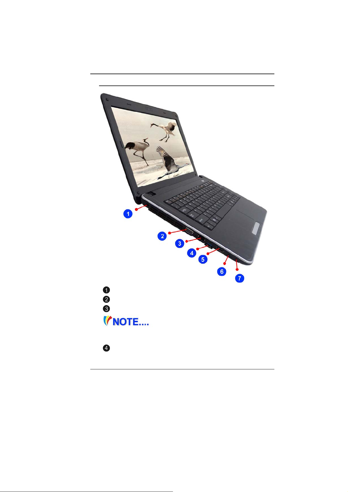
LLeefftt VViieewwss
Kensington Lock
CRT Port
Ethernet / LAN Port
When using a LAN, please use an
EMI Shielding Cable to minimize interference when
transmitting.
USB 2.0 Ports or 3.0 Ports (Optional)
12
Page 18
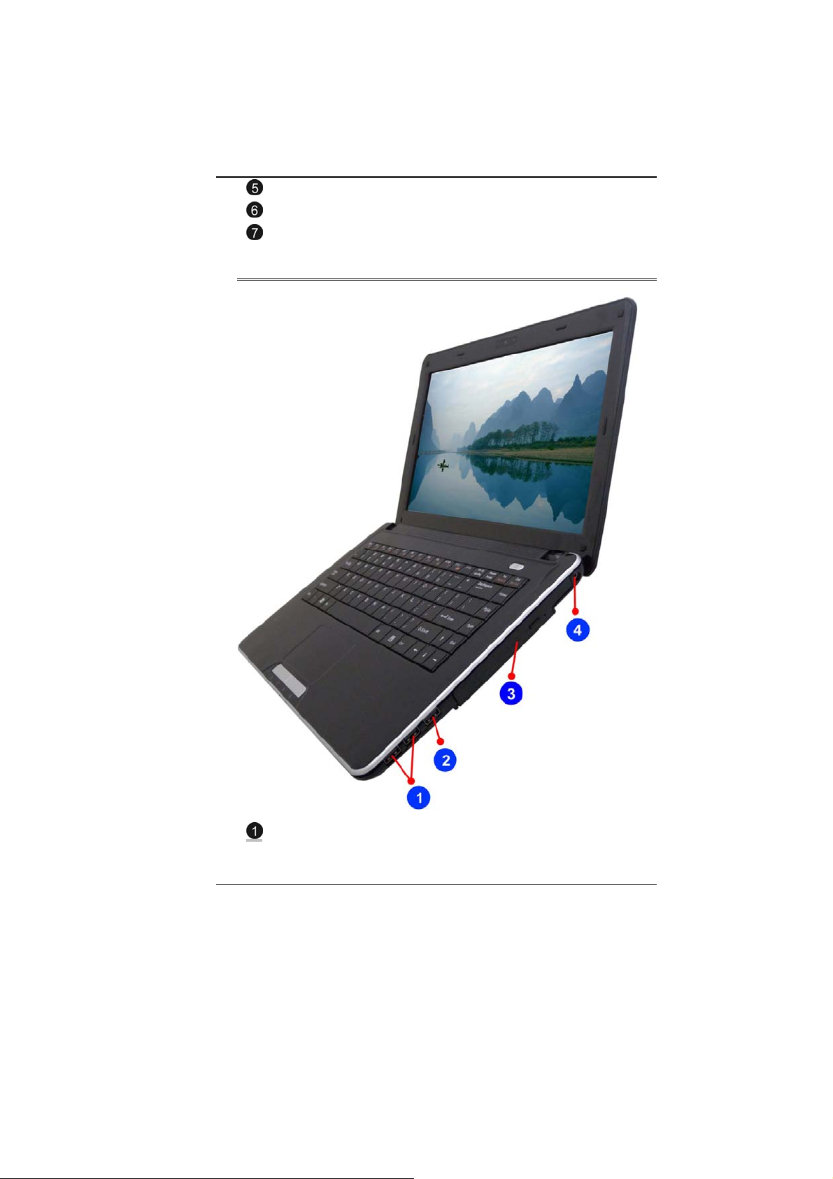
HDMI Port
Microphone/Audio Line-in Jack
Stereo Headphone Jack
RRiigghhtt VViieeww
USB 2.0 Port
13
Page 19

Enhanced USB 2.0 Port
Optical Drive
DC In
BBoottttoomm VViieeww
Battery Lock
Battery Compartment
Battery Release Latch
14
Page 20

15
Page 21

GGeettttiinngg SSttaarrtteedd
CCoonnnneeccttiinngg ttoo aa PPoowweerr SSoouurrccee
CCoonnnneeccttiinngg tthhee AACC AAddaapptteerr
A universal AC adapter is provided to supply your computer with
power and also charge the computer’s battery pack. The adapter’s
AC input voltage can range anywhere from 100 to 240 volts,
covering the standard voltages available in almost every country.
To connect the computer to an external power source:
DDoo nnoott uussee iinnffeerriioorr eexxtteennssiioonn
ccoorrddss aass tthhiiss mmaayy rrees
nnootteebbooookk ccoommees
ddiiffffeerreenntt aad
ddeevviicceess..
Whenever possible, keep the AC adapter plugged into the
notebook and an electrical outlet to recharge the battery.
16
daapptteerr ttoo ppoowweerr tthhee ccoommppuutteerr aanndd ootthheerr eelleeccttrriiccaall
suulltt iinn ddaammaaggee ttoo yyoouurr nnootteebbooookk.. TThhee
s
wwiitthh iittss oowwnn AACC aaddaapptteerr.. DDoo nnoott uussee aa
Page 22

NNeevveerr ttuurrnn ooffff oorr rreesseett yyoouurr
nnootteebbooookk wwhhiillee tthhee hhaar
ssoo ccaann
aatt lleeaasstt 55 sseeccoonnddss aafftteerr ttuurrnniinngg ooffff yyoouurr nno
ttuurrnniinngg iitt bbaacckk oonn;; ttuurrnniinngg tthhee ppoowweer
ssuucccceessssiioonn ccaann ddaammaaggee tthhee nnoot
rreessuulltt iinn lloossss oorr ddeessttrruuccttiioonn ooff yyoouurr ddaattaa.. AAllwwaayys
rdd ddiisskk iiss iinn uussee ssttaattuuss iiccoonn iiss lliitt;; ddooiinngg
o
tteebbooookk bbeeffoorree
r oonn aanndd ooffff iinn rraappiidd
t
eebbooookk’’ss eelleeccttrriiccaall cciirrccuuiittrryy..
TTuurrnniinngg OOnn YYoouurr NNootteebbooookk CCoommppuutteerr
Hold the button down for a second or two and release. The PowerOn Self Test (POST) runs automatically.
After the POST is completed, the computer reads the operating
system from the hard disk drive into computer memory (this is
commonly referred to as “booting” a computer). If your OS
(Operating System such as Windows Vista…. etc) is installed, it
should start automatically.
To turn the notebook off, save your work and close all open
applications, click on Start, then Shu
down the computer and click "Y
4-6 seconds.
OOppeerraattiinngg oonn BBaatttteerryy PPoowweerr
Your computer comes with a rechargeable battery pack that lets
you operate the computer without an external power source.
When the battery pack is fully charged, you can operate the
computer under the following conditions:
t Down and select Shut
es" or press the power button for
s wwaaiitt
The battery pack initially has a full charge.
No peripheral devices are installed.
The disk/DVD-ROM drives run no more than 10% of the time
OOnnllyy uussee bbaatttteerriieess tthhaatt aarree
aapppprroovveedd bbyy aann aauutthhoorriiz
ssaammee aanndd tthhe
roonngg bbaatttteerryy ccoouulldd ccaauussee sseerriioouuss ddaammaaggee ttoo yyoouurr ccoomm
wwr
aanndd yyoouurrsseellff tthhrroouugghh ttooxxiicc eemmiissssiioonnss..
e
rreeffoorree sshhoouulldd nnoott bbee ttrreeaatteedd aass ssuucchh.. UUssiinngg tthhee
zeedd ddeeaalleerr.. AAllll bbaatttteerriieess aarree nnoott tthhee
ppuutteerr
17
Page 23

DDaannggeerr ooff eexxpplloossiioonn iiff bbaatttteerryy iiss
iinnccoorrrreeccttllyy rreepplla
ttyyppee rreec
bbaatttteerriie
llaawwss..
c
ess aaccccoorrddiinngg ttoo tthhee mmaannuuffaaccttuurreerr’’ss iinnssttrruuccttiioonnss oorr
acceedd.. RReeppllaaccee oonnllyy wwiitthh ssaammee oorr eeqquuiivvaalleenntt
oommmmeennddeedd bbyy tthhee mmaannuuffaaccttuurreerr.. DDiissccaarrdd uusseedd
IInnssttaalllliinngg aanndd RReemmoovviinngg tthhee BBaatttteerryy PPaacckk
TToo IInnssttaallll tthhee BBaatttteerryy PPaacckk::
llooccaall
18
Page 24

TToo RReemmoovvee tthhee BBaatttteerryy PPaacckk::
CChhaarrggiinngg tthhee BBaatttteerryy PPaacckk
The installed battery pack charges automatically any time the
computer is connected to the AC adapter and an external power
source. It is a good idea to occasionally discharge the battery pack
fully to preserve its operating performance.
19
Page 25

20
Page 26

UUssiinngg tthhee NNootteebbooookk
CCoommppuutteerr
AAddjjuussttiinngg tthhee LLCCDD SSccrreeeenn DDiissppllaayy
The LCD screen display can be adjusted by the following key
combinations.
F4 - Changes Display Mode: LCD-only, CRT/HDMI-only and
simultaneous LCD&CRT/HDMI.
F7 - Decrease the brightness level.
F8 - Increase the brightness level.
LLCCDD CCaarree
LCD screens are delicate devices that need careful handling.
Please pay attention to the following precautions:
When you are not using the computer, keep the LCD screen
If you need to clean your LCD screen, use a soft tissue to
Do not put your fingers or sharp objects directly on the
Do not press on, or store any objects on the cover when it is
closed to protect it from dust.
gently wipe the LCD surface.
surface and never spray cleaner directly onto the display.
closed. Doing so may cause the LCD to break.
EExxtteerrnnaall CCRRTT DDiissppllaayy
You can hook up an external monitor through the 15-pin CRT
connector.
LCD only
CRT/HDMI only
Simultaneous LCD&CRT/HDMI
You can switch between these display configurations by pressing
the key combination [Fn] + [F4].
21
Page 27

TThhee NNootteebbooookk’’ss HHoott KKeeyy CCoonnttrroollss
Fn + F1 : Suspend
Fn + F2 : Fan/Silent Mode
Fn + F3 : Mute
Fn + F4 : LCD/CRT/HDMI
Fn + F5 : Volume down
Fn + F6 : Volume up
Fn + F7 : Brightness down
Fn + F8 : Brightness up
Fn + F9 : Touch Pad disable/enable
Fn + F10 : Wireless LAN On/Off
Fn + F11 : Webcam On/Off
Fn + Esc : Bluetooth On/Off
TThhee TToouucchhPPaadd
The touchpad is a rectangular electronic panel located just below
your keyboard. You can use the static-sensitive panel of the
touchpad and slit it to move the cursor. You can use the buttons
below the touchpad as left and right mouse buttons.
TToouucchhPPaadd PPrreeccaauuttiioonnss
The TouchPad is a pressure sensitive device. Please take note of
the following precautions.
Make sure the TouchPad does not come into contact with
22
Page 28

dirt, liquids or grease.
Do not touch the TouchPad if your fingers are dirty.
Do not rest heavy objects on the TouchPad or the TouchPad
buttons.
You can use the TouchPad with Microsoft Windows as well as nonWindows applications.
CCoonnnneeccttiinngg aann EExxtteerrnnaall TTrraacckkiinngg DDeevviicceess
The system will only enable you to use one tracking device
whether it is an internal or external tracking device.
DDaattaa SSttoorraaggee aanndd RReettrriieevvaall
Data storage and retrieval are two of the most fundamental tasks
you will perform when working with your computer. The Notebook
is equipped with a hard disk drive (HDD). The HDD is removable
allowing for easy upgrades.
PPoowweerr SSaavviinngg MMooddeess
This section contains information on the notebook’s power system,
including the AC Adapter, the battery system, recharging the
battery, and tips for conserving battery power.
The power system is comprised of two parts, the AC Adapter and
the battery system. The AC Adapter converts AC power from a wall
outlet to the DC power required by the computer.
TThhee BBaatttteerryy PPoowweerr SSyysstteemm
Before using the computer on battery power for the first time,
check the battery status icon on the Windows Toolbar to make
sure the battery is fully charged.
See Battery Status later in this section for a description and
explanation of the Windows Battery icon.
Charging the battery takes about 3 hours to charge when the
system is in off state. If possible, always charge the battery
completely.
23
Page 29

IIff yyoouu uussee tthhee bbaatttteerryy ssoo ffrreeqquueennttllyy tthhaatt iitt
d mmoorree tthhaann 2200 ttiimmeess bbyy ffuullllyy ddiisscchhaarrggiinngg//cchhaarrggiinngg
eexxcceeeed
ssiinnggllee mmoonntthh aalloonnee,, wwee rreeccoommmmeenndd yyoouu ttoo ppeerrffoor
““BBaatttteerryy CCaalliibbrraattiioonn”” pprroocceessss eevveerryy 33 mmoonntthhs
bbaatttteerryy lliiffee..
PPlleeaassee rreeffeerr ttoo tthhe
hhooww ttoo
ppaarrtt ooff tthhiiss cchhaapptteerr..
IIff yyoouu ddiissccoovveerr tthhee bbaatttte
ppeerrffoorrmm tthhee ““BBaat
RReemmoovviinngg tthhee BBaatttteerryy PPaacckk
To remove the battery pack from its compartment, please refer to
Chapter 3, Inserting and Removing the Battery Pack.
e ttooppiicc oonn ““BBaatttteerryy CCaalliibbrraattiioonn”” ddeessccrriibbiinngg
ccaalliibbrraattee yyoouurr ssyysstteemm bbaatttteerryy ddiissccuusssseedd oonn tthhee llaattt
e
rryy lliiffee iiss ggeettttiinngg sshhoorrtteerr,, pplleeaassee
ttteerryy CCaalliibbrraattiioonn”” pprroocceessss iimmmmeeddiiaatteellyy..
PPrreeppaarriinngg tthhee BBaatttteerryy PPaacckk ffoorr UUssee ((BBaatttteerryy
CCaalliibbrraattiioonn))
Before using the battery pack for the first time, battery pack should
be calibrated in order to get accurate reporting of remaining battery
life status..
To calibrate the battery pack follows the instructions below:
1. Insert the battery into the battery compartment and turn on the
notebook. If the battery is completely without power go to the
next step. Otherwise, let the battery run down until the battery
low-low warning beeps are heard. The system will
automatically enter Suspend mode.
2. Turn the notebook off. Connect the AC adapter and let the
battery fully recharge. When the battery charge indicator turns
off, the battery is fully charged.
3. Turn On the notebook, let the battery run down until the
battery is in low-low state and you hear a warning beeps. The
system will automatically enter the Suspend mode. You can
now connect the AC adapter.
4. The battery pack is now calibrated properly.
In general, using the battery until the low-low battery-warning
indicator appears and fully recharges the battery each time (full
discharge/charge cycle) will ensure the accurate reporting of the
battery gauge status.
rmm tthhee
s
ttoo mmaaiinnttaaiinn tthhee
iinn aa
teerr
24
Page 30

AAuuttoommaattiicc BBaatttteerryy PPaacckk CChhaarrggiinngg FFuunnccttiioonn
To charge the battery, while the battery pack is in the notebook,
plug the AC adapter into the notebook and an electrical outlet.
The charging time is approximately 3-4 hours when the notebook is
turned off and approximately 6-7 hours when the notebook is
turned on.
When the battery is fully charged, the battery charge indicator
becomes off.
IIff ssyysstteemm rruunnss aatt hheeaavvyy llooaaddiinngg oorr iinn aa
hhiigghh tteemmppeer
h
cch
aarrggeedd.. YYoouu nneeeedd ttoo ccoonnttiinnuuee ttoo cchhaarrggee iitt wwiitthh tthhee A
aaddaapptteerr pplluuggggeedd iinn uunnttiill tthhee cchhaarrggiinngg LLEEDD ttuurrnnss
BBaatttteerryy SSttaattuuss
Windows 7 has an applet in the Control Panel that will display an
icon in the Windows taskbar indicating when the notebook is
running on battery power or is attached to the AC adapter.
This applet also displays a meter that indicates how much charge
is remaining in the battery.
BBaatttteerryy LLooww WWaarrnniinngg
When the pack initially reaches the “Battery Low” state
approximately 7 ~ 10 minutes of the usable battery life is left.
You will hear an audible beep signal every 15 seconds alerting you
to the “Battery Low” status. When the battery power reaches the
“Battery Low Low” status the beeping sound will accelerate.
Your battery now has 1 ~ 2 minutes of battery charge remaining.
You must save your data or connect AC power immediately;
otherwise, you may lose your data.
Continuous
beeping every 5
seconds
Beeping
accelerates
raattuurree eennvviirroonnmmeenntt,, tthhee bbaatttteerryy mmaayy nnoott bbee ffuullllyy
ooffff.
Sound Meaning
Battery Low: Indicates that there is 7 to 10
minutes charge remaining.
Battery Low Low: Indicates that there is 1 to
2 minutes of battery charge remaining. Save
your work and turn off the notebook, or
.
ACC
25
Page 31

connect the AC adapter.
When there is only one minute of battery charge remaining, the
notebook will suspend to the HDD and power off. You should
connect AC power and resume to save your work.
DDaannggeerr ooff eexxpplloossiioonn iiff bbaatttteerryy iiss
iinnccoorrrreeccttllyy rreepplla
e
ttyyppe
rreeccoommmmeennddeedd bbyy tthhee mmaannuuffaaccttuurreerr..
DDiissppoossee ooff uusseedd
iinnssttrruucct
iiss oonn aass tthhiiss mmaayy rreessuulltt iinn ddaattaa lloossss wwhheenn tthhee s
ppoowweerr..
t
iioonnss.. NNeevveerr rreemmoovvee tthhee bbaatttteerryy ppaacckk wwhhiillee tthhee ppoowwe
RReesseettttiinngg tthhee SSyysstteemm
After installing a software application package, you may be
prompted to reset the system to load the changed operating
environment.
To reset the system, or “reboot,” press the [Ctrl]+[Alt]+[Delete]
keys simultaneously. This is known as “warm boot.” This key
combination acts as “software” reset switch when you encounter
hardware or software problems, which lock up the notebook.
If this key combination does not shut down the notebook, you can
reset the notebook by using the notebook’s power button. Should
the notebook lock up for some reason, pressing this button powers
the notebook off.
AAddjjuussttiinngg tthhee BBrriigghhttnneessss
To adjust the brightness on the LCD screen, press and hold down
the [Fn] key in the lower left hand corner of the keyboard and
press the [F7] key to decrease the brightness or [F8] to increase
the brightness.
acceedd.. RReeppllaaccee oonnllyy wwiitthh tthhee ssaammee oorr eeqquuiivvaalleenntt
bbaatttteerriieess aaccccoorrddiinngg ttoo tthhee mmaannuuffaaccttuurreerr''ss
s
yysstteemm lloosseess
err
26
Page 32

UUssiinngg tthhee WWiinnddoowwss
HHeellpp WWiinnddoowwss
For Windows 7 help,
click Start Help and
Support icon will open
the dialog box.
DDeesskkttoopp
Desktop may vary differently on the software installed in your
notebook with different or additional shortcuts.
27
Page 33

Recycle Bin
Used for storing deleted files in case you want to recover and save
it in your system. The files will only be deleted from the Recycle
Bin permanently only if you empty it by right clicking your mouse
and select the “Empty Recycle Bin”.
Start Button
Allows easy access to all Windows programs.
28
Page 34

The Start menu allows you to adapt and show the programs used
most frequently. If you wish to keep an item, right click the item and
click Pin to Start menu.
Log Off will enable the current user to log off and allows a new
user to log on.
Turn Off Computer allows you to shut down, restart, and Stand by
modes for power saving purposes.
Taskbar
When you open a program, its icon is displayed at the taskbar for
you to conveniently move between programs by clicking the
relevant button.
To add or remove toolbars from the taskbar: right click an empty
spot on the taskbar, select Toolbars choose the toolbar you
want to a d d.
Notification
The icons that appear here are for quick access to some programs
and computer functions that you frequently used. To prevent
Windows 7 from hiding icons:
From an empty spot on the Taskbar, right click your mouse and
select the Properties, remove the checked mark on the Auto-hide
the taskbar.
29
Page 35

CCoonnttrrooll PPaanneell
It is in this area that you can change how Windows looks and
works. Click Start Control Panel dialog box. There are two
interfaces – Classic View.
30
Page 36

31
Page 37

IInntteerrnneett CCoonnnneeccttiioonn
UUssiinngg WWiirreelleessss LLAANN NNeettwwoorrkk ffoorr CCoonnnneeccttiioonn
ttoo IInntteerrn
neett
32
Page 38

33
Page 39

RRuunnnniinngg BBIIOOSS SSeettuupp
The Setup Utility is a hardware configuration program built into
your computer’s BIOS (Basic Input/Output System). It runs and
maintains a variety of hardware functions. It is menu-driven
software, which allows you to easily configure and change the
settings.
The BIOS contains manufacture’s default settings for the
computer’s standard operations. However, there are occasions
when you may be required to modify the default settings in the
BIOS.
The BIOS allows you to set up passwords to limit access to users.
This is an important feature because a great deal of vital
information is carried within the computer nowadays. Unauthorized
access can be prevented. Later in this chapter, you will learn how
to use this security feature.
EEnntteerriinngg tthhee BBIIOOSS SSeettuupp SSccrreeeenn
First turn on the power. When the BIOS perform the POST (PowerOn Self Test), press F2 key quickly to activate the BIOS Setup
Utility.
YYoouu mmaayy nneeeedd ttoo pprreessss FF22 kkeeyy ffaaiirrllyy
qquuiicckkllyy.. OOnnccee t
hhaavvee ttoo
rreettrryy bbyy ccyyccllee--ppoowweerr oonn aaggaaiinn
LLeeaavviinngg tthhee BBIIOOSS SSeettuupp SSccrreeeenn
When you have finished modifying the BIOS settings, exit the
BIOS. It takes a few seconds to record changes in the CMOS.
BBIIOOSS AAccttiioonn KKeeyyss
Function Key Command Description
ESC Exit
Enter
34
thhee ssyysstteemm bbeeggiinnss ttoo llooaadd WWiinnddoowwss,, yyoouu mmaayy
Leaves a sub-menu to return to the
previous menu OR exits the BIOS
setup while saving changes.
Go to Sub
Screen
Shows the Sub Menu
Page 40

F1 General Help Shows the Help Screen
F9 Default Set to default
F10 Save and Exit
<Tab> Select a field Selects the next field.
Select an item Selects the next upper item.
Select an item Selects the next lower item.
Select a menu Selects the right item
Select a menu Selects the left item
- Lower value
+ Higher value
Saves changes and reboots the
computer.
Selects the lower value within a
field.
Selects the higher value within a
field.
MMooddiiffyyiinngg tthhee BBIIOOSS SSeettttiinnggss
The BIOS setup main menu is subdivided into sub-menus. Each
menu item is described in this section.
35
Page 41

MMaaiinn SSeettuupp
36
Page 42

IInnffoo SSeettuupp
37
Page 43

AAddvvaanncceedd
SSeeccuurriittyy SSeettuupp
38
Page 44

BBoooott SSeettuupp
EExxiitt SSeettuupp
39
Page 45

40
Page 46

SSuuppeerr PPOOSSHH
Super POSH is an integrated AP which has great benefit for the
system. It includes “Super Power” “Super OSD” “Super Speed”
and “Super HDD.”
These applications enable you to run the power saving scheme in
your system, enable shortcut icon, optimize your system
configuration, and detect your system current status.
Super POSH System Tray
Use your mouse left button by clicking once on the icon will show
the status bar.
Use your mouse left button by clicking twice on the icon will show
the controller at the right side of the screen and main page.
41
Page 47

The main functions are as follows:
Capslock / Silent mode / Touchpad / WLAN / Webcam /
Bluetooth / Numlock / Scroll lock / Brightness / (sound)
volume / Discrete / UMA
SSuuppeerr PPoowweerr
Super Power provides an integrated page for
user to control power management.
It could increase battery life and provides
effectiveness of your system.
There are 4 Modes for selection with their description shown below:
42
Page 48

Mode Icon Description
Power
saving
Normal Balance system performance
Decrease system performance to
provide more battery life
High
performance
Dynamic
switch
Provide system best performance
Switch to “Power saving” &
“ Normal” mode automatically on
battery mode, and auto switch to
“High performance” mode when
plug-in.
Power Status
Show Current Power Source from AC or Battery.
Battery mode
Plug-in and Charging
Plug-in and Full AC only
Setting Page
LCD will be turned off after the interval time and
Monitor
HDD System will spin down disk after the interval time
setting of the OS if keyboard or mouse is not
operated and no movie/game
43
Page 49

Stand by
Brightness
CPU Power
Saving
Hibernate
and setting to OS.
System will sleep after the interval time and
setting to OS. Adjust range is “Never” to “5hrs”.
Show the LCD monitor brightness level through
EC sent out code.
*Brightness level synchronize with Fn-key.
Lower CPU level in order to save power
If users disable Hibernate, the option of Hibernate
will not show in “Setting Page.”
System will hibernate after the interval time and
setting to OS.
Adjust range is “Never” to “6hrs”.
Setting the idle time to hibernate must longer
than Standby.
Default
* Press “OK” after the change “Monitor” “HDD” Stand by” and
“Hibernate” items, and setting would be applied.
* Setting would be applied and saved automatically after the change
“Brightness” “CPU Power Saving” and “Default.”
AAddvvaanncceedd PPaaggee
Hibernate
Wallpaper Desktop background will be white.
Turn off LCD
If “default” was checked, mode would switch to
default setting.
If users disable Hibernate, the option of
Hibernate will not show in “Setting Page.”
Default: ON
Press button to turn off the LCD immediately.
Default: ON
44
Page 50

Turbo mode
Advance power
engine
SmartEye
Allow Windows
Power Plan
Auto Switch
Mode when
Plug-in/out
Power off Audio
Overclocking CPU instantly.
Function options depend on the definition
of product specification.
Drop efficacy to save the battery power.
Function options depend on the definition
of product specification.
LCD will be turn off automatically if user leaves
for a definite time.
Only when plug-in and webcam on.
If webcam is busy when executing the
Super POSH, Smarteye will be turn off
automatically.
Enable select Windows or Super POSH’s power
plan
The system will switch mode automatically.
When adaptor is plug in, the system will switch
to High Performance mode. When the adaptor
is unplug, the system will switch to Power
Saving mode.
Default: ON
Dynamic switch mode has higher priority.
Turn off audio power instantly to save the
battery power.
Function options depend on the definition
of product specification.
Quickkey for Super Power
Press Quick key to switch among each power management modes
and on-screen display.
Warning:
If the percentage of battery was under 10%, there will pop a
warning window on task icon.
45
Page 51

SSuuppeerr OOSSDD ((OOnn--SSccrreeeenn--DDiissppllaayy))
Super OSD provides several styles and
locations selection of OSD. And also could get
the current status of OSD from status bar.
>> or << to preview function and OSD pictures.
OSD Style: Blue, Green and Orange.
Status:
This area displayed the current status of OSD. Status bar will auto
46
Page 52

detect device connected in your system. If the color of the icon is
yellow, it means the function is working. If the color of the icon is
gray, it means the function is turn off.
The value of volume and brightness also show at the side.
The icon of status bar depends on product specification.
Caps Lock On/Off
Silent Mode On/Off
TouchPad On/Off
Power of WiFi On/Off
Webcam On/Off
Bluetooth On/Off
Number Lock On/Off
Scroll Lock On/Off
Brightness Level (0~7)
Mute On/Off
Volume Level (0~10)
3G On/Off
Moving status bar:
It would show on the screen as OS ones. It can be vertical or
horizontal, and can be moved arbitrarily.
Volume Level Definition: Volume level value are as below
Level 0 1 2 3 4 5 6 7 8 9 10
Volume
Value
0 1
~
10
11
~
20
21
~
30
31
~
40
41
~
50
51
~
60
61
~
70
71
~
80
81
~
90
91~
100
* When adjusting the volume level, volume value will become
current level x10 automatically.
There are two options to either enable or disable the OSD.
Uncheck the “Disable OSD”, the system will not show the
OSD picture.
47
Page 53

Uncheck the “Display OSD Status bar”, Status bar will be
closed.
MMB- depends on product specification.
OSD location: There are 9 locations for choosing.
An example is shown below where the OSD is shown on the lower
right corner of the screen.
48
Page 54

Super OSD functions are as follows:
The function will depend on the definition of product specification.
Function Preview
Bluetooth
Silent mode
Mute (speaker only)
Volume
Brightness
Touchpad
Wireless
Webcam
3G
Caps Lock
Num Lock
Scroll lock
49
Page 55

Web browser
Media player
Play
Previous
Rewind
Stop
Fast forward
Next
VGA/UMA
SSuuppeerr SSppeeeedd
Super Speed optimizes and cleans the system to
obtain the best effectiveness and fragmentation.
50
Page 56

OOppttiimmiizziinngg WWiinnddoowwss SSeettttiinngg::
Click “Optimize” button after selecting the optimizing options to
improve system performance. Click “Restore” button to restore
the system to original status. After “Optimize” or “Restore” are
executed, please reboot the computer for the changes to take
effect.
Click
about the options
The options are described in the following table:
Visual Effect Modify visual effect setting to increase the
Service Terminate uncommon programs running in the
Boot Speed up the time for booting up the system.
Shutdown Speed up the time to shutdown the system.
Network Modify network setting to improve the
System Modify system setting to increase the
will pop a .txt file describing the detailed information
Options Description
performance of the system.
background when Windows is running.
performance of the network.
performance of the system.
System Disk Cleanup:
Click “Analyze” button to analyze the system.
Click “Free” button after selecting the options to free up
system disk space.
51
Page 57

The options are described in the following table:
Options Description
System temporary
files
Internet temporary
file
Recycle bin Clean the Recycle Bin in Windows
Clean the unnecessary files in
Windows
Clean the browsing history in
Internet Explorer
System Disk Defragment:
This will show the HDD health status according to “Super HDD”
page. It will state a suggestion whether the HDD should be
defragmented.
52
Page 58

Status & Picture
SSuuppeerr HHDDDD
Super HDD displays the health status of HDD
and information of CPU and RAM.
Information of main HDD: Name, Type, Partitions and Total Size.
Use scroll bar to choose the partition, it will display File system,
Total Size and Free Size of in partitions.
HHaarrdd DDiisskk MMeennuu
Normal:
Show the HDD Health Index according to S.M.A.R.T result.
HDD Health Index Condition
HDD status will be healthy if all status
Healthy
of items are normal.
53
Page 59

HDD status is in warning state if there
Warning
Danger
are more than one warning item.
HDD status is in danger state if there
are more than one danger item.
Not Support
HDD does not support this function.
Advanced :
There were 46 attributes from S.M.A.R.T to determine the HDD
health Index.
Item's status depends on 3 main values: A: threshold, B: worst,
and C: current value. The rule of judging conditions as stated in the
following items:
CCPPUU
Information of the main CPU: CPU Name, CPU Tag, Cores
Number, Max clock Speed and Current Clock Speed.
Super POSH will auto detect the maximum temperature of CPU,
and display on the following table:
Display Status Percentage of
limit temperature
Normal Under 69% Green
Warning 70~89% Orange
Danger 90~100% Red
Color
RRAAMM::
Information of main RAM: Total Memory Size, Free Memory Size,
Percent of used RAM and Usage Processes Number.
54
Page 60

WWaarrnniinngg::
If the status of HDD and CPU is Danger, a warning window will pop
up on the POSH icon.
SSeettttiinngg ppaaggee
A: Show “about” in the top area. Include: Icon, Version, release
date and information of every pages.
B: Setting Options:
Advanced setting of super POSH.
Options Description Status
ToolTip Whether show ToolTip and
Refresh
time
C: Company information:
A customized area.
Depend on the definition of customer. Show Company name, email,
address…etc. Logo dimension (pixels): 350 x 80
Warning message
Refresh battery status time
* Refresh time would affect
synchronized time with OS and
discharge time.
ON/ OFF
1,2,3,5,10,30sec,
1,2,3,5min
55
Page 61

56
Page 62

Troubleshooting
Your computer has been fully tested and complies with the system
specifications before shipping. However, incorrect operations
and/or mishandling may cause problems.
This chapter provides a reference for identifying and correcting
common hardware and software problems that you may encounter.
When you encounter a problem, you should first try to go through
the recommendations in this chapter. Instead of returning the
computer and waiting for repair, you may easily solve the problems
by considering the following scenarios and possible solutions. If
the error continues, contact your reseller for service information.
Before taking further actions, consider the following suggestions:
Check to see if the problem persists when all the external
devices are removed.
Check to see that the blue light indicator on the AC adapter
is lit.
Check to see the power cord is properly plugged to the wall
outlet and to the computer.
Check to see the power indicator of the computer is on.
Check to see if your keyboard is operational by pressing and
holding any key.
Check for any incorrect or loose cable connections. Make
sure the latches on the connectors latch securely on to the
receptor end.
Be sure you have not performed an incorrect setting on the
hardware devices in the BIOS Setup utility. A faulty
setting may cause the system to misbehave. If you are
not sure of the changes you made, try to restore all the
settings to factory defaults.
Be sure all the device drivers are installed properly. For
example, without the audio driver properly installed, the
speakers and microphone will not work.
If external devices such as USB cameras, scanner, printer
do not function correctly when connected to the system, it is
usually the device’s own problem. Consult the device’s
manufacturer first.
Some software programs, which have not gone through
57
Page 63

rigorous coding and testing, may cause problems during
your routine use. Consult the software vendor for problem
solving.
Legacy peripheral are not plug-and-play capable. You need
to restart the system with these devices powered up and
connected first.
Be sure to go to BIOS SETUP and load DEFAULT SETTING
after BIOS re-flash.
58
Page 64

59
Page 65

SSppeecciiffiiccaattiioonn
O.S.
Support Windows 7 Home Premium x64, x32,
CPU
Intel
Memory
Dual-channel DDR3 frequency 1333MHz
SODIMM socket x2, Max. support to 8GB
®
Huron River Turbo Boost Technology 2.0
Frequency (no turbo boost function)
i3-2310M, 2.1GHz, 3M
Frequency(Base/ Turbo) L3 cache,
i5-2410M, 2.30~2.60GHz, 3MB
i5-2520M, 2.50~2.90GHz, 3MB
i5-2540M, 2.60~3.00GHz, 3MB
i7-2620M, 2.70~3.10GHz, 4MB
Core Logic
Intel Cougar Point
GPU
ATI Whistler-XT (128 bit)
Audio Codec
Realtek ALC269-GR
Card reader (4 in 1)
Support SDHC/MMC/MS/MS pro Memory Card
60
Page 66

LAN Controller
RTL8105E-VC-GR (Optional)
Supports 10/100Mb/sec
RTL8111E (giga)
Supports 10/100/ 1,000 Mb/sec
WLAN + BT Module Combo Card
PCIE Interface
Half-Mini Card
IEEE802.11 B/G/N W/Single antenna
BT 3.1 spec
Webcam
1.3M VGA / HD
USB interface
LED: AP ON w/ Blue color
Keyboard
US 86 keys KB
Pointing Device
PS2 Touch Pad with 2 buttons
Hidden type solution (under plastics)
Support multi-gesture
LCD
14.0” LED HD, Resolution 1366x768 (16:9) (slim :3.6mm)
Optical Drive
Super-Multi (Z-height 12.7mm)
GBAS bezel w/o printing
Support SATA interface only
Battery Pack
6 cells, 10.8V/4400mAh
Gallopwire H41-3S4400-G1L3 (3S2P) (47.52W)
6 cells, 11.1V/4400mAh
SIMPLO H41-3S4400-S1B1 (48.84W)
61
Page 67

6 cells, 10.8V/5200mAh
Gallopwire H41-3S5200-G1L5 (56.16W)
6 cells, 11.1V/5200mAh
SIMPLO H41-3S5200-S1B1 (57.72W)
AC-Adapter
Automatics Voltage adjustment between 100 and 240VAC
50/60Hz, 19V/90 Watts, Level 5, 2 Pins
Delta Electronic, Inc.
ADP-90SB-AB (90W, 2 pin)
Huntkey Electronic Co., LTD
HKA0901904/8D(90W, 2 pin)
Speaker/MIC
Build-in 2 speaker (1.5W), 1 sub-woofer (2W), 4Ω
Internal microphone, Sensitivity: -42db, Directivity: Omni-
directional, Impedance: 2.2KΩ
BIOS
Supports PnP, ACPI 3.0
Support external USB flash memory card boot up.
With Phoenix BIOS and Intel ME firmware on 4MB flash
ROM
Physical Outline
Dimension:
356.35 x 237.6 x 37.39 mm (w/ rubber foot)
356.4 x 237.6 x 32.39 mm (w/o rubber foot)
Weight: 2.3 kg, w/ 6 cell bat.
EMI
CE/FCC
RF
CE, R&TTE report/document, FCC
62
Page 68

Safety
CB/CCC
63
 Loading...