

Page 1

Solder Practice Kit
MODEL AK-100
Lesson Manual
Elenco Electronics, Inc.
Copyright © 1994 Elenco Electronics, Inc. REV-F 752601
Revised 2002
Elenco Electronics, Inc.
150 W. Carpenter Avenue
Wheeling, IL 60090
(847) 541-3800
http://www.elenco.com
e-mail: elenco@elenco.com
Page 2
Parts List
If you are a student, and any parts are missing or damaged, please see instructor or bookstore.
If you purchased this kit from a distributor, catalog, etc., please contact Elenco Electronics
(address/phone/e-mail is at the back of this manual) for additional assistance, if needed. DO
NOT contact your place of purchase as they will not be able to help you.
Resistors
Qty. Symbol Description Part #
1R3 68Ω 5% 1/4W (blue-gray-black-gold) 126800
2 R1, R7 470Ω 5% 1/4W (yellow-violet-brown-gold) 134700
1R2 1kΩ 5% 1/2W (brown-black-red-gold) 141001
2 R8, R9 10kΩ 5% 1/4W (brown-black-orange-gold) 151000
1 R5 47kΩ 5% 1/4W (yellow-violet-orange-gold) 154700
2 R4, R6 56kΩ 5% 1/4W (green-blue-orange-gold) 155600
1 VR1 200Ω Potentiometer 191321
Capacitors
Qty. Symbol Description Part #
2 C4, C5 .02µF Discap (203) or .022µF (223) 242280
3 C1, C2, C3 10µF Electrolytic (Lytic) 271045
1 C6 100µF Electrolytic (Lytic) 281044
Semiconductors
Qty. Description Part #
2 Transistor 2N3904 323904
1 IC 555 or 1455 330555
2 LED Red 350002
Miscellaneous
Qty. Description Part #
1 Printed Circuit Board 511500
1 Battery Snap 590098
1 Speaker 590102
12” Wire 814800
1 Soldering Iron 9SR1
1 Side Cutters 9ST1
1 Solder Roll 9ST4
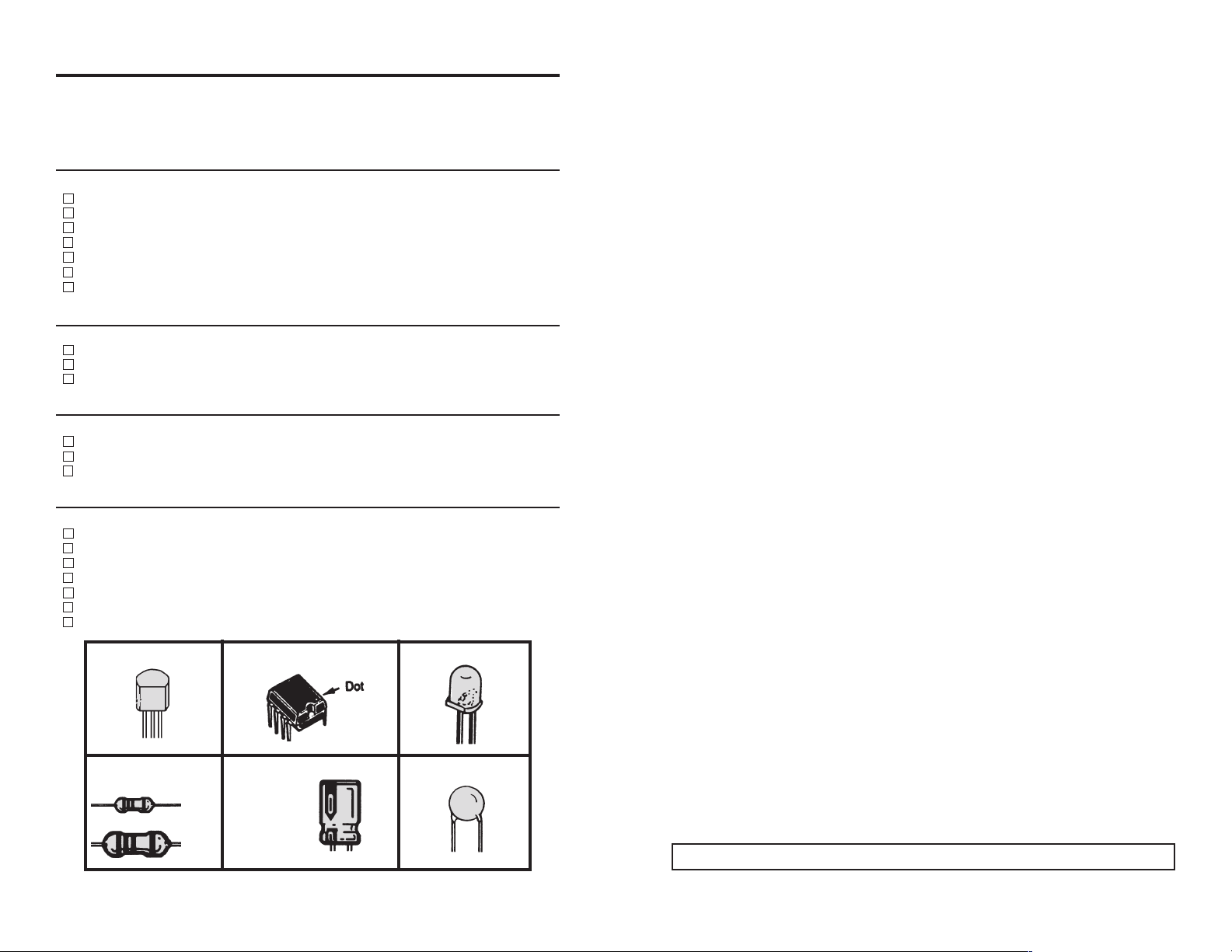
Figure 1, Parts Identification
-1- -10-
8. When two adjacent foils accidentally touch, it is called
A. a jumper.
B. a blob.
C. a solder hole.
D. a solder bridge.
9. What ratio has the greatest amount of tin?
A. 20/60
B. 40/60
C. 50/50
D. 60/40
10. A good solder connection should be
A. dull and rough.
B. shiny, bright and smooth.
C. lumped around the connection.
D. soldered on one side of the connection.
Answers: 1. B, 2. C, 3. A, 4. D, 5. B, 6. A, 7. C, 8. D, 9. D, 10. B
Transistor 2N3904
IC 555 or 1455 LED
Resistors
Electrolytic Capacitor
Ceramic Capacitor
+
1/2W
1/4W
Lytics have
polarity. Note the
marking on the
side before
mounting.
Page 3

Introduction
Almost every electronic device today has a printed circuit board whether
you are assembling a PC board or repairing it, you must understand the
basics of working with these boards.
A poorly soldered joint can greatly affect small current flow in circuits and
can cause equipment failure. You can damage a PC board or a
component with too much heat or cause a cold solder joint with
insufficient heat. Sloppy soldering can cause bridges between two
adjacent foils preventing the circuit from functioning.
Good soldering requires practice and an understanding of soldering
principles. This solder practice project will help you achieve good
soldering techniques, help you to become familiar with a variety of
electronic components, and provide you with dynamic results. If the
circuit has been assembled and soldered properly, the LED will
alternately flash and the speaker will produce a wailing sound.
Solder
Solder is a fusible alloy composed of tin and lead. Some solder may
contain small amounts of other material for use in special purposes to
enhance its characteristics. Solder has a melting temperature around
360
O
to 370O, making it ideal for forming a metallic joint between two
metals.
Solder is identified by the ratio of tin-to-lead. The most common ratios
are 40/60, 50/50 and 60/40. Solder with a greater tin content melts at a
lower temperature, takes less time to harden, and generally makes it
easier to do a good soldering job. The ratio of tin is a main factor in the
strength of the solder joint. Solder with a greater tin content has a greater
holding ability under stress. Solder with a tin ratio of 60% is the strongest,
while solder with less than 30% would be undesirable.
Flux
Most solder contains flux in the hollow core of the solder allowing it to be
applied automatically when you heat the solder. The flux will remove any
oxide film on the metals soldered creating a good metal-to-metal contact.
This is called “wetting the metal”. There are three types of solder of solder
fluxes: chloride, organic and rosin. In the electronics industry, only the
rosin type is used. Rosin flux comes in two types, pure and active. The
most reliable is the pure type, since it doesn’t cause dendrites between
tracks on the PC board as the active type does. Due to the highly
corrosive and moisture attracting characteristics of the chloride and
organic type fluxes, they should not be used in electronics.
-2-
-9-
Quiz
1. Solder is comprised of what two materials?
A. gold and copper.
B. tin and lead.
C. zinc and copper.
D. lead and aluminum.
2. What type of flux should be used in electronics?
A. chloride.
B. organic.
C. rosin.
D. corrosive.
3. When working on PC boards, what wattage range of iron is ideal?
A. 15-40 watts.
B. 50-100 watts.
C. 1-10 watts.
D. 100-200 watts.
4. Tinning the soldering tip will prevent it from
A. heating.
B. melting.
C. soldering.
D. oxidating.
5. Proper solder adhesion requires that the metal surface to be
A. solder free.
B. clean.
C. greasy.
D. cold.
6. Solder wick is used to
A. remove solder.
B. solder in small parts.
C. cleaning the soldering iron tip.
D. removing flux.
7. A cold solder joint is caused by
A. a solder bridge.
B. using 60/40 solder.
C. insufficient heat.
D. acid core solder.
Page 4

-3-
Types of Soldering Devices
A number of different types of soldering devices: irons, guns and stations
are available today. Irons are used for light to medium work and guns are
for medium to heavy-duty work. The station type can range from light to
heavy-duty. When working on PC boards, a soldering iron is ideal. Iron
sizes vary from 15 to over 500 watts. For working on PC boards, irons
ranging from 15 to 40 watts is suitable. If you use an iron with a higher
wattage rating than 40 watt, you may damage the copper tracks on the
PC board. The higher wattage irons are best suited for heavy-duty
electrical jobs.
Solder Tips
The material that the tip is made from is an important factor. Most tips are
made of copper coated with some other material. The molten solder on
the tip will wear it down. To increase their lifetime, tip can be coated with
iron, but this decreases the heat transfer rate. The tip should be tinned
by lightly coating it with solder. This will prevent it from oxidating. The tip
becomes pitted (black spots) from normal use. You can remove these
spots by scraping them with a knife or filing item. After removing the
spots, you should re-tin the tip. It is important to clean the tip by wiping it
with a wet rag or sponge. A good clean solder tip makes soldering much
easier.
Today, tips are manufactured in a variety of different shapes (see figure
below). The chisel shape is one of the most common. Having a choice
of tip styles allows you to choose the one best suited for your soldering
needs. Due to the high heat, removable tips can bond themselves to the
heating element if left in place for extended periods of time. Periodic
removal of the tip is therefore advisable.
Theory of Operation
The solder practice kit produces the sound of the European siren. It
consists of two oscillators, a one hertz (one cycle per second) and a
1500Hz. The one hertz oscillator consists of two transistors Q1 and Q2,
and resistors R1, R2, R6 and R7 capacitors C1 and C2. This
configuration is known as a multivibrator circuit.
When voltage is first applied to this multivibrator circuit, one transistor
(possibly Q1) will conduct faster, causing transistor Q2 to stay off. Q1 will
continue to conduct until it saturates. At this point, Q2 will start to conduct,
causing Q1 to rapidly cutoff. This process continues alternately causing Q1
or Q2 to conduct. The output will be a square wave. The frequency is
determined by the time constants of resistor R6 and capacitor C1, also R4
and C2. Two LED diodes are placed in the collectors of the transistors and
will light when current is passing through them. Resistors R2, R1 and R7
determine the current passing through the LEDs.
Integrated circuit IC1 is the heart of the second oscillator. A 555 timer IC
is used in the circuit. This IC contains many transistors and resistors on
a silicon chip and thus eliminates many external parts. The frequency of
this oscillator is determined by resistors R5, R9 and capacitor C4.
Capacitor C3 couples the output of operations of IC1 via resistor R8. This
changes the operations of IC1 during one half cycle of the multivibrator
causing the frequency to change from 1500Hz to 2200Hz. This results in
a speaker output that varies constantly in pitch. The multivibrator circuit
not only causes the LED to flash, but also varies the pitch at the speaker
output.
Troubleshooting
If you are experiencing a problem, first read the theory of operations to
familiarize yourself with the operation. Remember, there are two
oscillators. If no sound comes out of the speaker, but the LED flashes
alternately, then the 555 timer is not working. Be sure that the volume
control is at maximum. Check the components IC1, R5, R8, R9, C3, C4
and C5. Be sure that the IC is in properly.
If a steady sound (not wobbling) comes out of the speaker, then the
multivibrator is not working. Check the components associated with
transistor Q1 and Q2. Check the LED by shorting the transistor collector
to the emitter. The LED should light. If not, then the LED is either open
or backwards.
-8-
Precision
Electronic
Pencil
Chisel
Micro
Spade
Pyramid
Long Taper
Chisel
Screwdriver
Tapered
Needle
Stepped
Chisel
Chisel
Chisel
Fork
Soldering Iron
Soldering Gun
Soldering Station
Page 5

Clean Connections
Proper solder adhesion requires that the metal surface to be free of dirt
and grease. The flux only removes the oxides so a brush or rag can be
used to clean metal. There are contact cleaners in aerosol cans and
other solvents available.
Desoldering
Great care should be taken when repairing or correcting a mistake on a
PC board. The metal foil can be easily pulled up or broken from excessive
heat. Use the least amount of heat as possible. You can use a
desoldering tool, bulb, wick or a station. These tools will remove the
solder enabling you to correct the problem.
Soldering Components to the PC Board
A. A 15 to 40 watt pencil type soldering iron with a 1/8” or 3/16” pyramid
works well.
B. The soldering iron tip must be kept clean at all times. Wipe it on a wet
sponge or cloth, then tin the entire tip to give it a wet look. This will
prevent the tip from oxidizing.
C. Always use rosin core solder, type 60/40 (60% tin, 40% lead). Never
use acid core solder, for it will damage the components.
-4--7-
Circuit Board Assembly
Note that electrolytic capacitors, transistors, LEDs and the IC must be
installed according to their polarity. Refer to Figure 1 for identification.
Figure 3
After completing the assembly of the kit, double back to see that the
soldering looks good and all of the components are in their proper place.
If everything is all right, attach the 9V battery to the battery snap. The
LEDs should alternately light and the speaker should sound a wobbling
siren.
Battery Snap
C5 - .02µF or .022µF
Discap
C6 - 100µF Lytic
Note polarity
IC1 555 or 1455
Note dot marking
6” Wires (strip 1/4”
off of both ends)
VR1 200Ω
Volume Control
(these holes not used)
R3 - 68Ω Resistor
(blue-gray-blk-gold)
R2 - 1kΩ 1/2W
(brn-blk-red-gold)
C2 - 10µF Lytic
Note polarity
Q1, Q2 - 2N3904
transistors (note flat)
LED - Note flat
R9 - 10kΩ Resistor
(brn-blk-orange-gold)
R8 - 10kΩ Resistor
(brn-blk-orange-gold)
Jumper Wire, use
cut-off from resistors
R7 - 470Ω Resistor
(yel-vio-brn-gold)
C3 - 10µF Lytic
Note polarity
R6 - 56kΩ Resistor
(grn-blue-org-gold)
R5 - 47kΩ Resistor
(yel-vio-org-gold)
C4 - .02µF or .022µF
Discap
R4 - 56kΩ Resistor
(grn-blue-org-gold)
C1 - 10µF Lytic
Note polarity
R1 - 470Ω Resistor
(yel-vio-brn-gold)
Jumper Wire
LED - Note flat
After completing the above assembly, twist the two speaker wires together
and solder to speaker lugs.
Cut 12” wire into two 6” wires.
D. Solder all components from the copper
foil side only. Push the soldering iron tip
against both the lead and the circuit
board foil.
Red
Black
Battery Snap
Desoldering Tool
Bulb
Solder Wick
Desoldering Station
Component Lead
Soldering Iron
Circuit Board
Foil
Page 6

Soldering Project Procedure
Before we begin to assemble and solder components to the solder
practice board, we will practice large pads on the edge of the PC board,
see Figure 2. Soldering should be smooth and neat. Next, solder to the
smaller pads. Be sure that there is no solder bridging. Try intentionally to
make a solder bridge. Then, remove it by lifting the PC board over the
soldering iron and the iron will draw the solder away from the pads. It is
best to wipe the iron tip with a damp cloth to remove the solder. Finally,
you will note the large rectangle pads. These are used to practice “tack
soldering”. Strip the end of the wire and practice soldering the wire to the
pads. Remove the wire when finished.
The PC board is covered with solder resist over areas that are not to be
soldered. This is done to reduce soldering shorts to adjacent metal runs.
On the large pad, note that half of the pad is covered with solder resist.
Try soldering the wire to the covered pad. You will find that it is impossible
to solder.
Refer to Figure 3 and begin the PC board assembly with resistor R9. Be
sure to identify the correct value by reading the color code (brown-blackorange-gold). Place the resistor into the PC board with the leads coming
out on the copper foil side. Solder in place and clip off the excess wire
close to the connection. Proceed clockwise with the other components.
Check off the box when you have completed that step.
E. Apply a small amount of solder to the iron
tip. This allows the heat to leave the iron
and flow into the foil. Immediately apply
solder to the opposite side of the
connection, away from the iron. Allow the
heated component and circuit foil to melt
the solder.
F. Allow the solder to flow around the
connection. Then, remove the solder and
iron and let the connection cool. The
solder should flow uniformly and not lump
around the wire. The connection should be
bright, shiny and smooth.
G. Poor solder connections occur when the
lead is not heated sufficiently. This is
called a “cold” solder joint. The solder will
not adhere to the lead as shown. To
correct this, reheat the connection and if
necessary, apply a small amount of
additional solder to obtain a good
connection.
-5-
H. When the foil is not heated sufficiently, the
solder will blob on the circuit board. To
correct this, reheat the connection and if
necessary, apply a small amount of
additional solder to obtain a good
connection.
I.
A solder bridge may form if you accidentally
touch an adjacent foil, particularly a
previously soldered connection, use too
much solder, or drag the soldering iron
across adjacent foils. Remove any solder
bridges with your soldering iron.
J. Do not allow components to move when
solder is cooling. It may not solder
properly and result in a cold solder joint.
Components should be placed as close to
the board as possible. Bend the leads to
hold the part in place while soldering.
-6-
Figure 2 Practice Solder Area
Rosin
Soldering iron
positioned incorrectly.
Tack Solder
Pad
Small Pads
Large Pads
Solder
Soldering Iron
Foil
Solder
Soldering Iron
Foil
Poor solder
connection
Soldering iron positioned
incorrectly.
 Loading...