

Page 1
Copyright © 2013 by ELENCO®Electronics, Inc. All rights reserved. No part of this book shall be reproduced by 753154
any means; electronic, photocopying, or otherwise without written permission from the publisher.
REV-A
Patent #‘s: 7,144,255, 7,273,377, & other patents pending
Project A3
Page 2
-1-
WARNING: SHOCK HAZARD - Never connect Snap
Circuits
®
to the electrical outlets in your home in any way!
WARNING: CHOKING HAZARD - Small
parts. Not for children under 3 years.
!
Conforms to all
applicable U. S.
government standards.
1. Most circuit problems are due to incorrect
assembly, always double-check that your
circuit exactly matches the drawing for it.
2. Be sure that parts with positive/negative
markings are positioned as per the drawing.
3. Be sure that all connections are securely
snapped.
4. Try replacing the batteries.
5. If the motor spins but does not balance the
fan, check the black plastic piece with three
prongs on the motor shaft.
ELENCO®is not responsible for parts damaged
due to incorrect wiring.
Basic Troubleshooting
Note: If you suspect you have damaged parts, you
can follow the Advanced Troubleshooting procedure on
page 8 to determine which ones need replacing.
Basic Troubleshooting 1
Parts List 2
About Your Snap Circuits®Parts 3 - 5
Introduction to Electricity 6
DO’s and DON’Ts of Building Circuits 7
Advanced Troubleshooting 8
Project Listings 9
How to Use Snap Circuits® 10
Part A – Introductory Projects (A1-A30)
11 - 27
Part B – Microcontroller Projects (B1-B27)
28 - 58
Part C – To Go Further 59
Other Snap Circuits®Products 62
Table of Contents
WARNING: Always check your wiring before
turning on a circuit. Never leave a circuit
unattended while the batteries are installed.
Never connect additional batteries or any
other power sources to your circuits. Discard
any cracked or broken parts.
Adult Supervision: Because children’s
abilities vary so much, even with age groups,
adults should exercise discretion as to which
experiments are suitable and safe (the
instructions should enable supervising
adults to establish the experiment’s
suitability for the child). Make sure your child
reads and follows all of the relevant
instructions and safety procedures, and
keeps them at hand for reference.
This product is intended for use by adults
and children who have attained sufficient
maturity to read and follow directions and
warnings.
Never modify your parts, as doing so may
disable important safety features in them, and
could put your child at risk of injury.
• Use only 1.5V “AA” type, alkaline batteries (not
included).
• Insert batteries with correct polarity.
• Non-rechargeable batteries should not be
recharged. Rechargeable batteries should only
be charged under adult supervision, and should
not be recharged while in the product.
• Do not connect batteries or battery holders in
parallel.
• Do not mix old and new batteries.
• Do not mix alkaline, standard (carbon-zinc), or
rechargeable (nickel-cadmium) batteries.
• Remove batteries when they are used up.
• Do not short circuit the battery terminals.
• Never throw batteries in a fire or attempt to open
its outer casing.
• Batteries are harmful if swallowed, so keep away
from small children.
Batteries:
!
WARNING TO ALL PROJECTS WITH A SYMBOL - Moving parts. Do not touch the motor or fan during operation. Do not
lean over the motor. Do not launch the fan at people, animals, or objects. Eye protection is recommended.
!
!
!
Requirements for your computer: Windows®
XP (or later) or Mac OS X 10.2 (or later) or Linux,
512MB RAM, 500MB of hard-disk space, USB
port, and an internet connection.
Page 3
-2-
Important: If any parts are missing or damaged, DO NOT RETURN TO RETAILER. Call toll-free (800) 533-2441 or e-mail us at:
help@elenco.com. Customer Service • 150 Carpenter Ave. • Wheeling, IL 60090 U.S.A.
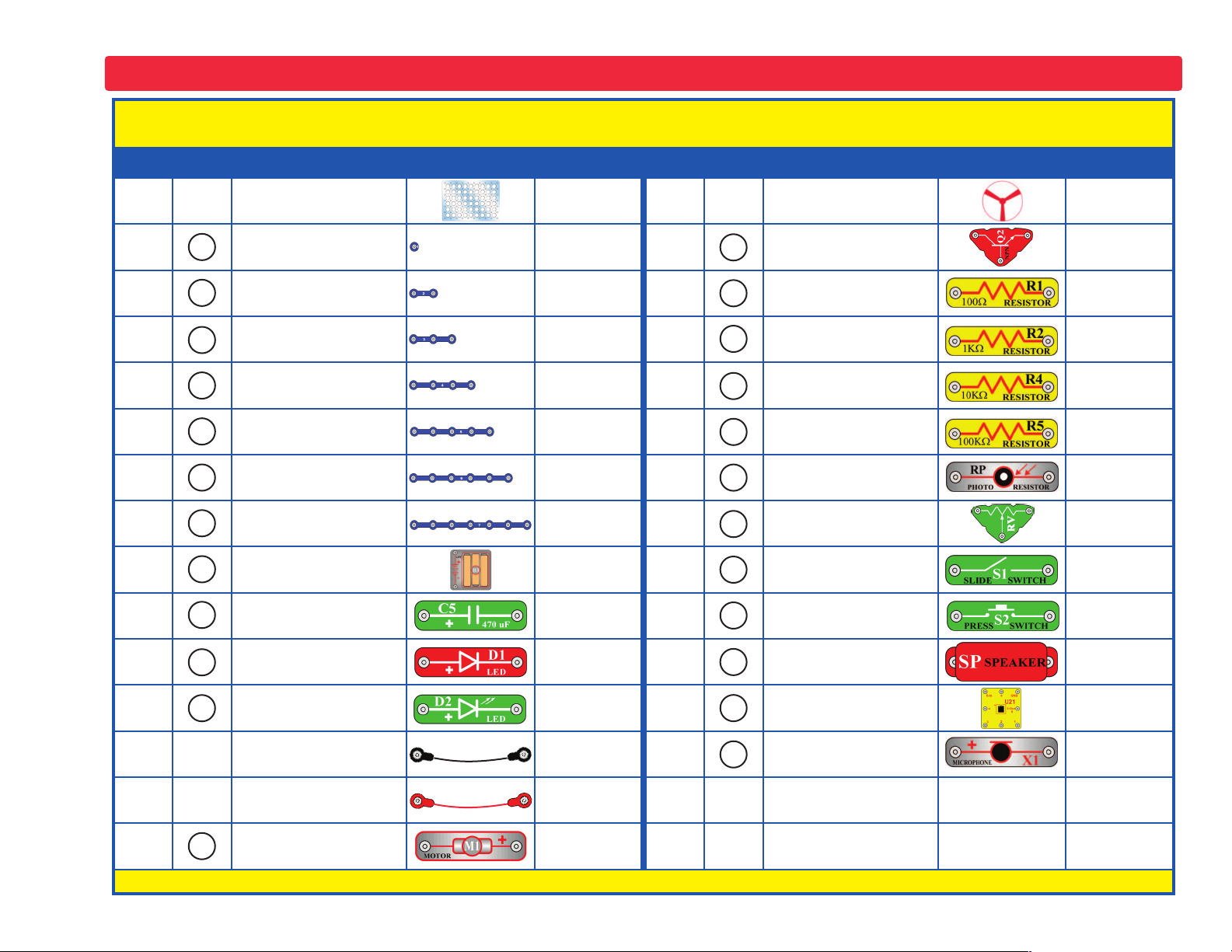
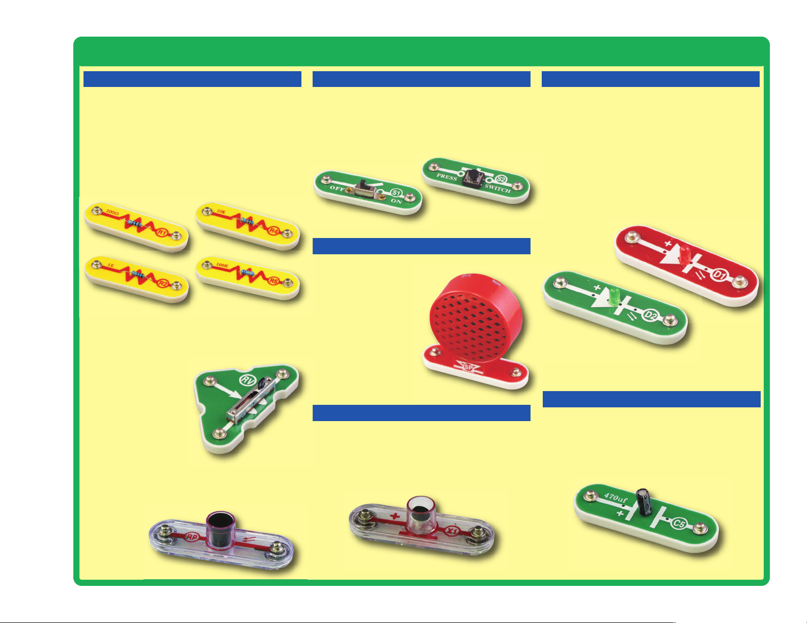
Parts List (Colors and styles may vary) Symbols and Numbers
Qty. ID Name Symbol Part # Qty. ID Name Symbol Part #
r 1
Base Grid
(11.0” x 7.7”)
6SCBG
r 1
Fan Blade 6SCM1F
r 6
1-Snap Wire 6SC01
r 2
NPN Transistor 6SCQ2
r 9
2-Snap Wire 6SC02
r 1
100W Resistor 6SCR1
r 4
3-Snap Wire 6SC03
r 2
1kW Resistor 6SCR2
r 3
4-Snap Wire 6SC04
r 2
10kW Resistor 6SCR4
r 1
5-Snap Wire 6SC05
r 1
100kW Resistor 6SCR5
r 1
6-Snap Wire 6SC06
r 1
Photoresistor 6SCRP
r 1
7-Snap Wire 6SC07
r 1
Adjustable Resistor 6SCRV
r 1
Battery Holder - uses
3 1.5V type AA (not
Included)
6SCB3
r 1
Slide Switch 6SCS1
r 1
470mF Capacitor 6SCC5
r 1
Press Switch 6SCS2
r 1
Red Light Emitting
Diode (LED)
6SCD1
r 1
8 Ohm Speaker 6SCSP
r 1
Green Light Emitting
Diode (LED)
6SCD2
r 1
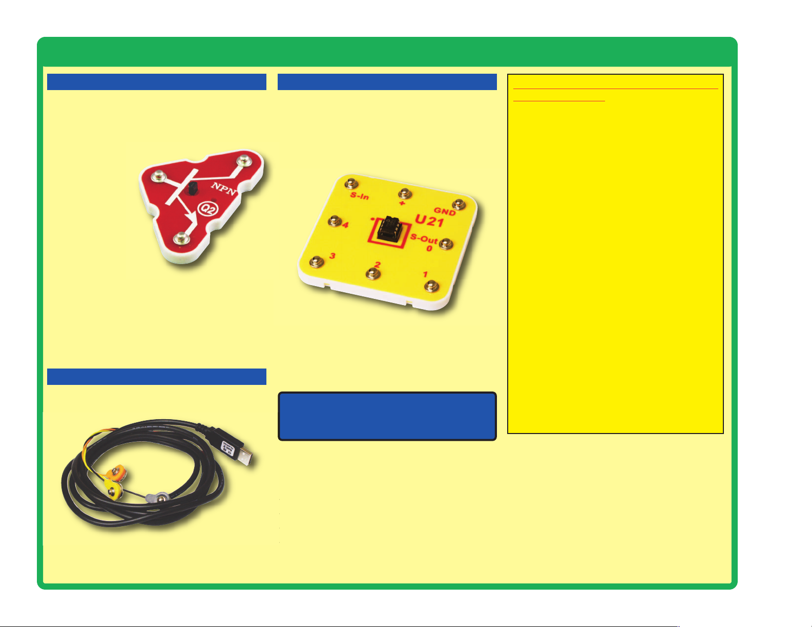
Microcontroller IC 6SCU21
r 1
Jumper Wire (Black) 6SCJ1
r 1
Microphone 6SCX1
r 1
Jumper Wire (Red) 6SCJ2
r 1
Programming Cable 9TLSCXP
r 1
DC Motor 6SCM1
You may order additional / replacement parts at our website: www.snapcircuits.net
5
4
3
2
1
RP
U21
S2
R2
X1
B3
D1
C5
D2
R1
SP
6
7
M1
Q2
R5
R4
RV
S1
Page 4
-3-
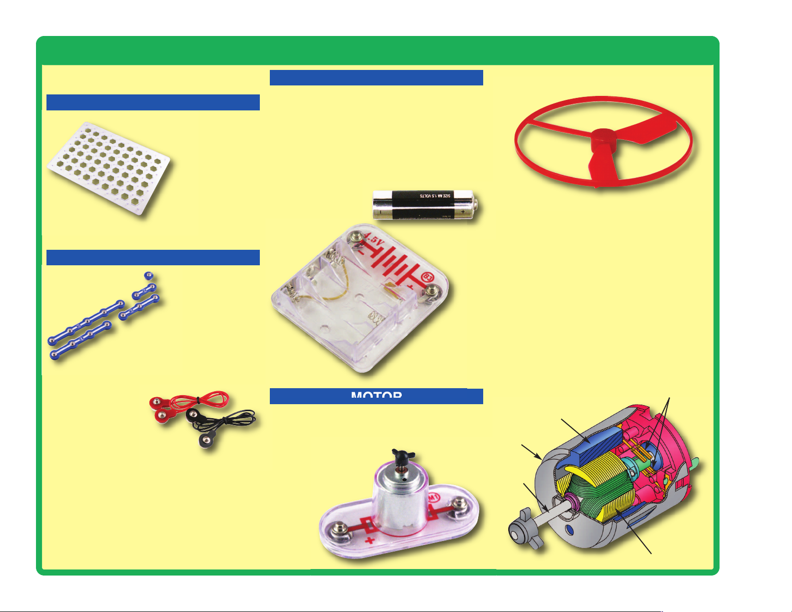
About Your Snap Circuits
®
XP Parts
(Part designs are subject to change without
notice).
BASE GRID
SNAP WIRES & JUMPER WIRES
MOTOR
Magnet
Electromagnet
Shaft
Power Contacts
Shell
Motor (M1)
BATTERY HOLDER
Battery Holder (B3)
The batteries (B3) produce an electrical voltage
using a chemical reaction. This “voltage” can be
thought of as electrical pressure, pushing
electricity through a circuit just like a pump
pushes water through pipes. This voltage is
much lower and much safer than that used in
your house wiring. Using more batteries
increases the “pressure”, therefore, more
electricity flows.
The blue snap wires
are wires used to
connect components.
They are used to
transport electricity and do
not affect circuit performance.
They come in different lengths to
allow orderly arrangement of connections
on the base grid.
The red and black
jumper wires make
flexible connections for
times when using the snap wires
would be difficult. They also are
used to make connections off the base grid.
Wires transport electricity just like pipes are used
to transport water. The colorful plastic coating
protects them and prevents electricity from
getting in or out.
The base grid is a platform for
mounting parts and wires.
It functions like the
printed circuit
boards used in
most electronic
products, or like how
the walls are used for
mounting the electrical
wiring in your home.
The motor (M1) converts electricity into
mechanical motion. An electric current in the
motor will turn the shaft and the motor blades,
and the fan blade if it is on
the motor.
Fan
How does electricity turn the shaft in the motor?
The answer is magnetism. Electricity is closely
related to magnetism, and an electric current
flowing in a wire has a magnetic field similar to
that of a very, very tiny magnet. Inside the motor
is a coil of wire with many loops wrapped around
metal plates. This is called an electromagnet. If
a large electric current flows through the loops,
it will turn ordinary metal into a magnet. The
motor shell also has a magnet on it. When
electricity flows through the electromagnet, it
repels from the magnet on the motor shell and
the shaft spins. If the fan is on the motor shaft,
then its blades will create airflow.
Page 5
-4-
About Your Snap Circuits
®
XP Parts
RESISTORS
MICROPHONE
SPEAKER
SLIDE & PRESS SWITCHES RED & GREEN LEDs
CAPACITOR
Resistors (R1, R2, R4, & R5)
Resistors “resist” the flow of electricity and are
used to control or limit the current in a circuit.
Snap Circuits
®
XP includes 100W (R1), 1kW (R2),
10kW (R4), and 100kW(R5) resistors (“K”
symbolizes 1,000, so R4 is really 10,000W).
Materials like metal have very low resistance
(<1W), while materials like paper, plastic, and air
have near-infinite resistance. Increasing circuit
resistance reduces the flow of electricity.
The slide & press switches (S1 & S2) connect
(pressed or “ON”) or disconnect (not pressed or
“OFF”) the wires in a circuit. When ON they have no
effect on circuit performance. Switches turn on
electricity just like a faucet turns on water from a pipe.
Slide & Press Switches (S1 & S2)
The speaker (SP) converts electricity into sound
by making mechanical
vibrations. These vibrations
create variations in air
pressure, which travel
across the room. You
“hear” sound when your
ears feel these air
pressure variations.
Speaker (SP)
The microphone (X1) is actually a resistor that
changes in value when changes in air pressure
(sounds) apply pressure to its surface. Its
resistance typically varies from around 1kW in
silence to around 10kW when you blow on it
Microphone (X1)
The photoresistor (RP) is a light-sensitive
resistor, its value changes from nearly infinite in
total darkness to about 1000W when a bright light
shines on it.
Photoresistor (RP)
The adjustable resistor (RV) is a 50kW resistor
but with a center tap that can be adjusted
between 200W and 50kW.
Adjustable Resistor (RV)
The 470mF capacitor (C5) can store electrical
pressure (voltage) for periods of time. This
storage ability allows it to block stable voltage
signals and pass changing ones. Capacitors are
used for filtering and delay circuits.
Capacitor (C5)
The red & green LED’s (D1 & D2) are light
emitting diodes, and may be thought of as a
special one-way light bulb. In the “forward”
direction, (indicated by the “arrow” in the symbol)
electricity flows if the voltage exceeds a turn-on
threshold (about 1.5V for red and a little higher
for green); brightness then increases. A high
current will burn out the LED, so the current must
be limited by other components in the circuit.
LED’s block electricity in the “reverse” direction.
LED’s (D1 & D2)
Page 6
-5-
About Your Snap Circuits
®
XP
TM
Parts
The NPN (Q2) transistors are components that
use a small electric current to control a large
current, and are used in switching, amplifier, and
buffering applications. They are easy to
miniaturize, and are the main
building blocks of
integrated circuits
including the
microprocessor and
memory circuits in
computers.
TRANSISTORS
U21 Microcontroller IC:
(+) - power from batteries
(GND) - power return to batteries
S-In - Programming input snap
S-Out /Snap 0 - Serial Output 0
Snap 1 - IN1/OUT1/ADC1
Snap 2 - IN2/OUT2/ADC2
Snap 3 - IN3
Snap 4 -IN4/OUT4/ADC4
Note: There is additional information for
the PICAXE®08M2 integrated circuit at
www.picaxe.co.uk.
The programming cable is used to program and
communicate with the U21 microcontroller.
CABLES
MICROCONTROLLER
Microcontroller outputs cannot control the motor
or speaker directly, an interface transistor must
be used. Microcontroller outputs can control Snap
Circuits
®
LEDs directly.
Programming Cable
NPN Transistor (Q2)
The microcontroller IC (U21) includes the
PICAXE®08M2 integrated circuit. This is a mini
computer which can be programmed to perform
different tasks, including monitoring things and
making things happen. The PICAXE
®
08M2 has
a special programming interface that makes it
very easy to use.
Microcontroller IC (U21)
Notes for using the PICAXE®-08M2 in
other applications:
Power source:
This should be 4.5V or 5V. Higher voltages
may damage the part.
S-In connection:
The U21 platform has an internal 10KW
resistor between the S-In and GND snaps,
and a 22KW resistor between the S-In snap
and the microcontroller. These facilitate use of
the programing cable.
Several snaps can be used as either
inputs, outputs, or analog to digital
converters:
as Outputs: Each output can supply or
receive up to 20 mA. This is enough to light an
LED, but an interface transistor must be used
when controlling a motor or speaker.
as Inputs: An input should be above 80% of
the power source voltage to be high, or below
20% of the power source voltage to be low.
as Analog to Digital Converters (ADC): The
ADC range is the power source voltage range.
Circuit resistance should be less than 20KW,
or false readings may occur.
Page 7
Introduction to Electricity
What is electricity? Nobody really knows. We only know how to produce it,
understand its properties, and how to control it. Electricity is the movement
of sub-atomic charged particles (called electrons) through a material due
to electrical pressure across the material, such as from a battery.
Power sources, such as batteries, push electricity through a circuit, like a
pump pushes water through pipes. Wires carry electricity, like pipes carry
water. Devices like LEDs, motors, and speakers use the energy in
electricity to do things. Switches and transistors control the flow of
electricity like valves and faucets control water. Resistors limit the flow of
electricity.
The electrical pressure exerted by a battery or other power source is called
voltage and is measured in volts (V). Notice the “+” and “–” signs on the
battery; these indicate which direction the battery will “pump” the electricity.
The electric current is a measure of how fast electricity is flowing in a
wire, just as the water current describes how fast water is flowing in a pipe.
It is expressed in amperes (A) or milliamps (mA, 1/1000 of an ampere).
The “power” of electricity is a measure of how fast energy is moving
through a wire. It is a combination of the voltage and current (Power =
Voltage x Current). It is expressed in watts (W).
The resistance of a component or circuit represents how much it resists
the electrical pressure (voltage) and limits the flow of electric current. The
relationship is Voltage = Current x Resistance. When the resistance
increases, less current flows. Resistance is measured in ohms (W), or kilo
ohms (kW, 1000 ohms).
Nearly all of the electricity used in our world is produced at enormous
generators driven by steam or water pressure. Wires are used to efficiently
transport this energy to homes and businesses where it is used. Motors
convert the electricity back into mechanical form to drive machinery and
appliances. The most important aspect of electricity in our society is that it
allows energy to be easily transported over distances.
Note that “distances” includes not just large distances but also tiny
distances. Try to imagine a plumbing structure of the same complexity as
the circuitry inside a portable radio - it would have to be large because we
can’t make water pipes so small. Electricity allows complex designs to be
made very small.
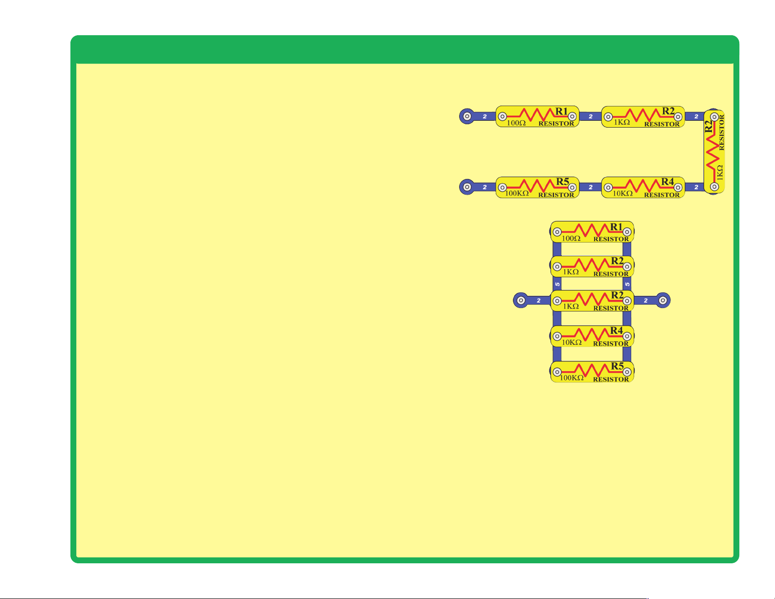
There are two ways of arranging parts in a circuit, in
series or in parallel. Here are examples:
Placing components in series increases the resistance;
highest value dominates. Placing components in parallel
decreases the resistance; lower value dominates.
The parts within these series and parallel sub-circuits
may be arranged in different ways without changing what
the circuit does. Large circuits are made of combinations
of smaller series and parallel circuits.
-6-
Series Circuit
Parallel Circuit
Page 8
-7-
DO’s and DON’Ts of Building Circuits
After building the circuits given in this booklet, you may wish to experiment on your own.
Use the projects in this booklet as a guide, as many important design concepts are
introduced throughout them. Every circuit will include a power source (the batteries), a
resistance (which might be a resistor, capacitor, motor, integrated circuit, etc.), and wiring
paths between them and back.
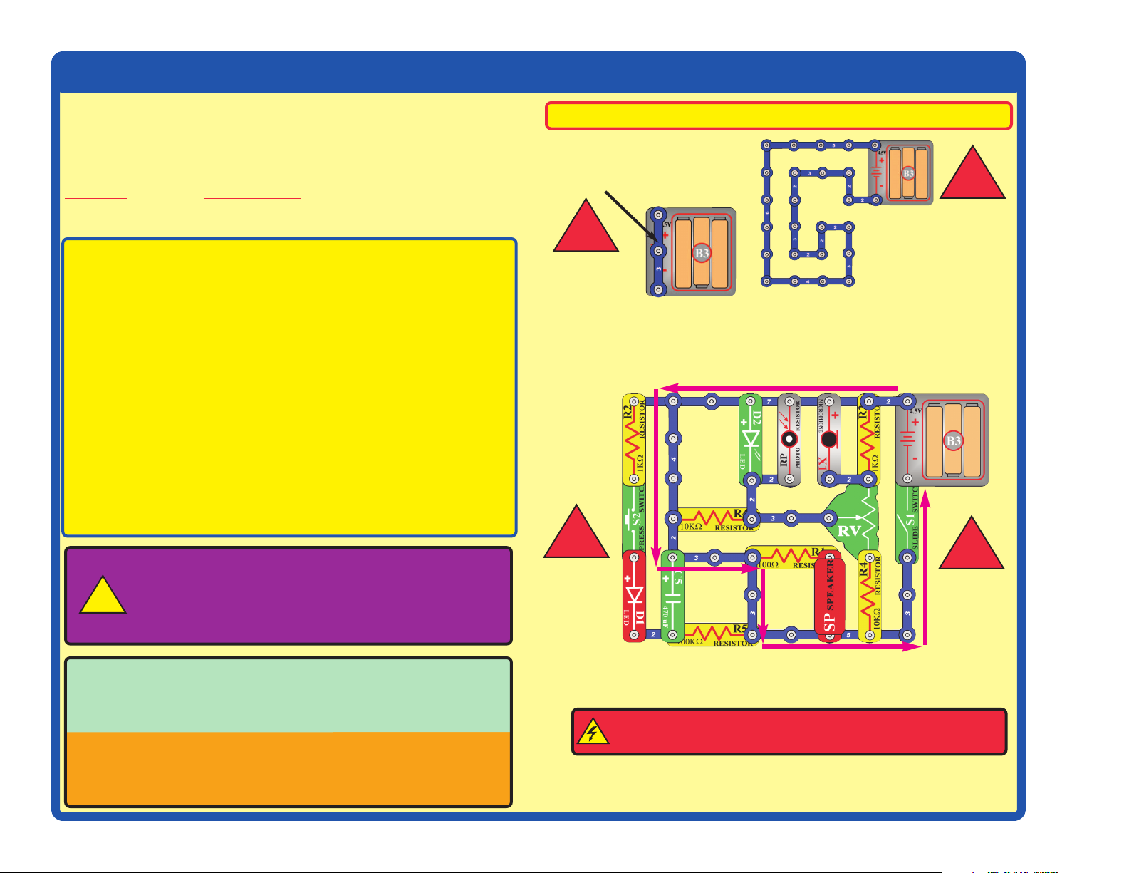
You must be careful not to create “short circuits” (very lowresistance paths across the batteries, see examples at right) as this will damage
components and/or quickly drain your batteries. Only connect the U21 microcontroller IC
(the PICAXE 08M) using configurations given in the projects, incorrectly doing so may
damage it. ELENCO®is not responsible for parts damaged due to incorrect wiring.
Here are some important guidelines:
ALWAYS USE EYE PROTECTION WHEN EXPERIMENTING ON YOUR OWN.
ALWAYS include at least one component that will limit the current through a circuit, such
as the speaker, capacitors, ICs (which must be connected properly), motor,
microphone, photoresistor, or resistors.
ALWAYS use LEDs, transistors, and switches in conjunction with other components that
will limit the current through them. Failure to do so will create a short circuit
and/or damage those parts.
ALWAYS connect capacitors so that the “+” side gets the higher voltage.
ALWAYS disconnect your batteries immediately and check your wiring if something
appears to be getting hot.
ALWAYS check your wiring before turning on a circuit.
ALWAYS connect U21 microcontroller IC using configurations given in the projects or
as per the connection description on page 5.
NEVER connect to an electrical outlet in your home in any way.
NEVER touch the motor when it is spinning at high speed.
Placing a 3-snap wire directly
across the batteries is a
SHORT CIRCUIT.
This is also a
SHORT CIRCUIT.
When the slide switch (S1) is turned on, this large circuit has a SHORT
CIRCUIT path (as shown by the arrows). The short circuit prevents any
other portions of the circuit from ever working.
NEVER
DO!
NEVER
DO!
NEVER
DO!
NEVER
DO!
Examples of SHORT CIRCUITS - NEVER DO THESE!!!
Warning to Snap Circuits®owners: Do not use
parts from other Snap Circuits
®
sets with this kit. Other
sets use higher voltage which could damage the
microcontroller and other parts.
You are encouraged to tell us about new programs and circuits you
create. If they are unique, we will post them with your name and state
on our website at www.snapcircuits.net/kidkreations.htm. Send
your suggestions to ELENCO
®
: elenco@elenco.com.
ELENCO®provides a circuit designer so that you can make your own
Snap Circuits
®
drawings. This Microsoft®Word document can be
downloaded from www.snapcircuits.net/SnapDesigner.doc or
through the www.snapcircuits.net website.
WARNING: SHOCK HAZARD - Never connect Snap Circuits
®
to the electrical outlets in your home in any way!
!
!
!
!
!
Page 9
Advanced Troubleshooting
(Adult supervision recommended)
-8-
ELENCO
®
150 Carpenter Avenue
Wheeling, IL 60090 U.S.A.
Phone: (847) 541-3800
Fax: (847) 520-0085
e-mail: help@elenco.com
Website: www.elenco.com
You may order additional /
replacement parts at:
www.snapcircuits.net
ELENCO®is not responsible for parts
damaged due to incorrect wiring.
If you suspect you have damaged parts,
you can follow this procedure to
systematically determine which ones need
replacing:
(Note: Some of these tests connect an LED
directly across the batteries without another
component to limit the current. Normally this
might damage the LED, however Snap Circuits
®
LEDs have internal resistors added to protect
them incorrect wiring, and will not be damaged.)
1. LEDs (D1 & D2), motor (M1), speaker
(SP), and battery holder (B3): Place
batteries in holder. Place one of the LEDs
directly across the battery holder (LED + to
battery +), it should light. Do the same for
the motor, it should spin. “Tap” the speaker
across the battery holder contacts, you
should hear static as it touches. If none
work, then replace your batteries and
repeat. If still bad, then the battery holder is
damaged.
2.
Jumper wires:
Use this minicircuit to test
each jumper
wire, the LED
should light.
3.
Snap wires: Use this mini-circuit to test
each of the snap wires, one at a time. The
LED should light.
4.
Slide switch (S1) and Press switch (S2):
Use this mini-circuit; if the LED doesn’t light
then the slide
switch is bad.
Replace the
slide switch
with the press
switch to test it.
5.
100W (R1), 1kW (R2), and 10kW (R4)
resistors:
Use the mini-circuit from test 4
but replace the switch with the 100W resistor
(R1); the LED will be bright if the resistor is
good. Next use the 1kW and 10kW resistors
in place of the 100W resistor; the LED
should be dimmer but still light.
6.
Microphone (X1) and Photoresistor (RP):
Use the mini-circuit from test 4 but replace
the switch with the microphone (X1, + on
right); if blowing into the microphone does
not change the LED brightness then the
microphone is bad. Replace the microphone
with the photoresistor. Waving your hand
over the photoresistor (changing the light
that shines on it) should change the
brightness of the LED or the photoresistor is
bad.
7.
Adjustable resistor (RV): Build Project
#A16, the resistor control lever should turn
the LED (D1) on and off; otherwise it is bad.
8.
NPN transistor (Q2): Build the mini-circuit
shown here. The LED (D2) should only be
on if the press switch (S2) is pressed. If
otherwise, then the NPN is damaged.
9.
470mF capacitor (C5) and 100kW
resistor (R5):
Build the mini-circuit shown
here. When you press the switch, the LED
should be bright but then slowly get dim,
otherwise the
capacitor is bad.
Replace the 1kW
resistor (R2)
with the 100kW
resistor (R5); the
LED should stay
on much longer
or R5 is bad.
10.
Programming cable: Connect the cable
to the red LED (D1), orange and yellow
wires to (+) and black wire to the other
side. Run the AXEpad for Snap Circuits®
XP software. Open a terminal (press F8).
Type something into the output buffer and
press Send. The red LED should flash and
what you typed should appear in the input
buffer.
11.
Microcontroller (U21): Use project B27
(Test the Microcontroller).
Page 10

Project Listings
Part A - Introductory Projects: These projects introduce you to the
Snap Circuits®method of building circuits and show how electronic
components work. No computer is needed for these projects (some
projects use the U21 microcontroller, but with a factory-loaded program).
Part B - Microcontroller Projects: These projects are an
introduction to microprocessors, and the flexibility they give by being
programmable. A computer is needed to load programs into the
microcontroller, but no other programming knowledge is needed. The
microcontroller re-programming procedure is explained in project B1.
Part C - To Go Further: This section is intended for users who
would like to develop their own programs for the microcontroller. It
also has bonus circuits for owners of other Snap Circuits
®
models.
-9-
Project # Title Page #
A1 Electric Light 11
A2 Controlling Electricity 11
A3 Dancing Motor 12
A4 Electronic Counter 13
A5 Adding Sound to the Counter 14
A6 Daylight Alarm Clock 14
A7 Intruder Alarm 15
A8 Jukebox 16
A9 Counting to the Stars 17
A10 Angles and Distance 18
A11 Flip-Flop 19
A12 Adjustable Light Timer 19
A13 Light Sensitive Timer 20
A14 Shot in the Dark 20
A15 Microphone Control 21
A16 Adjustable Brightness 21
A17 Conduction Detector 21
A18 Slider 22
A19 Parallel Resistors 22
A20 Series Resistors 22
A21 Flying Saucer 23
A22 Transistor 23
A23 Capacitor Battery 24
A24 Blow Off Sound 24
A25 Capacitor Photo Control 25
A26 Capacitor Photo Control with Slow Shut-off 25
A27 Photo Switcher 26
A28 Blow On Sound 26
A29 Scratchy Amplifier 27
Project # Title Page #
A30 One Shot 27
B1 Blinker (Programming the Microcontroller) 29
B2 Blinkers 33
B3 Four Outputs 34
B4 Play a Tune 35
B5 Computer Music Box 36
B6 Random Sounds 38
B7 Sloppy Switches 39
B8 Bounceless Switches 40
B9 Jukebox with Terminal 41
B10 Launch Pad 42
B11 Adjustable Blinker 43
B12 Basic Light Meter 44
B13 Capacitor Discharge 45
B14 Sunrise Alarm 46
B15 Photon Counter 47
B16 Photon Kazoo 47
B17 Click Counter 48
B18 Super Click Counter 49
B19 Data Logger 50
B20 Data Logger with Cost 51
B21 24 Hour Data Logger 52
B22 Digital Voltmeter 53
B23 Battery Tester (4V or less) 54
B24 Battery Tester (20V or less) 55
B25 Clap Light 56
B26 Clap Music 57
B27 Test the Microcontroller 58
Page 11
How to Use Snap Circuits
®
Snap Circuits®uses building blocks with snaps
to build the different electrical and electronic
circuits in the projects. Each block has a
function: there are switch blocks, light blocks,
battery blocks, different length wire blocks, etc.
These blocks are different colors and have
numbers on them so that you can easily
identify them. The blocks you will be using are
shown as color symbols with level numbers
next to them, allowing you to easily snap them
together to form a circuit.
For Example:
This is the switch block which is green and has
the marking on it. The part symbols in this
booklet may not exactly match the appearance
of the actual parts, but will clearly identify them.
This is a wire block which is blue and comes
in different wire lengths.
This one has the number , , , , ,
or on it depending on the length of the wire
connection required.
There is also a 1-snap wire that is used as a
spacer or for interconnection between different
layers.
You need a power source to build each circuit.
This is labeled and requires three (3) “AA”
batteries (not included).
A large clear plastic base grid is included with
this kit to help keep the circuit blocks properly
spaced. You will see evenly spaced posts that
the different blocks snap into. The base has
rows labeled A-G and columns labeled 1-10.
Next to each part in every circuit drawing is a
small number in black. This tells you which
level the component is placed at. Place all
parts on level 1 first, then all of the parts on
level 2, then all of the parts on level 3, etc.
Some circuits use the jumper wires to make
unusual connections. Just clip them to the
metal snaps or as indicated.
Usually when the motor is used, the fan will
be placed on it.
No computer is needed for introductory
projects (some projects use the U21
microcontroller, but with a factory-loaded
program).
Occasionally you may feel static electricity if
you touch a circuit when the programming
cable is connected, usually when humidity is
very low. Don’t worry; this is harmless. It
occurs because the cable makes an easy
electrical path between your body and the
ground, allowing static that has built up on you
to dissipate. Sometimes this static electricity
may reset the microcontroller (U21), causing it
to re-start its program.
Note: While building the projects, be
careful not to accidentally make a direct
connection across the battery holder (a
“short circuit”), as this may damage and/or
quickly drain the batteries.
S2
2
3 4 5
6
B3
-10-
PART A - Introductory Projects
7
M1
Page 12
-11-
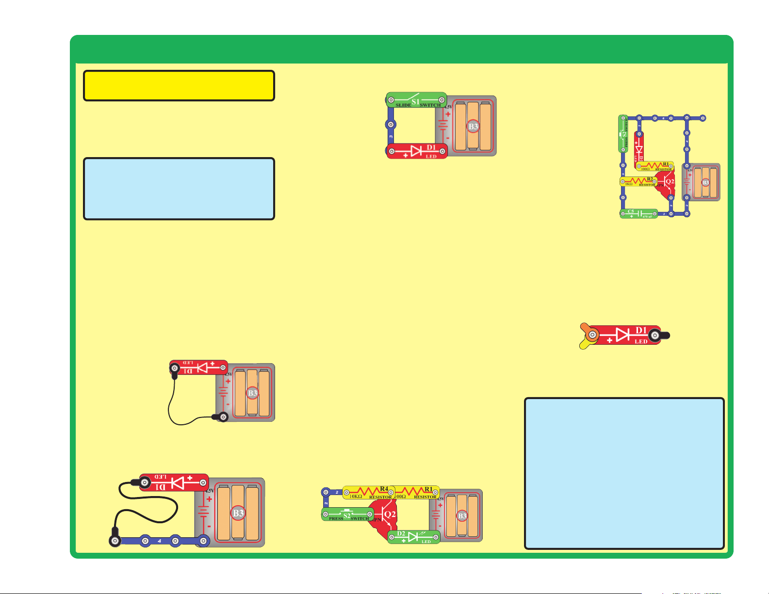
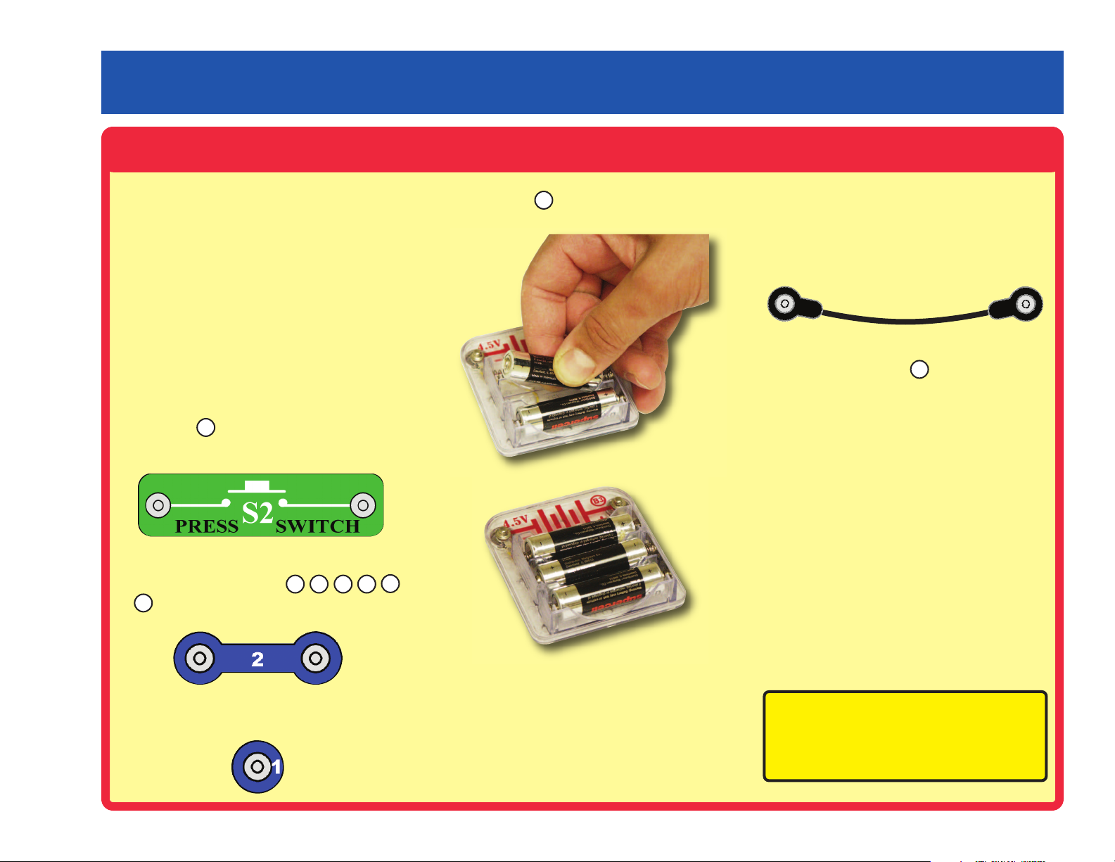
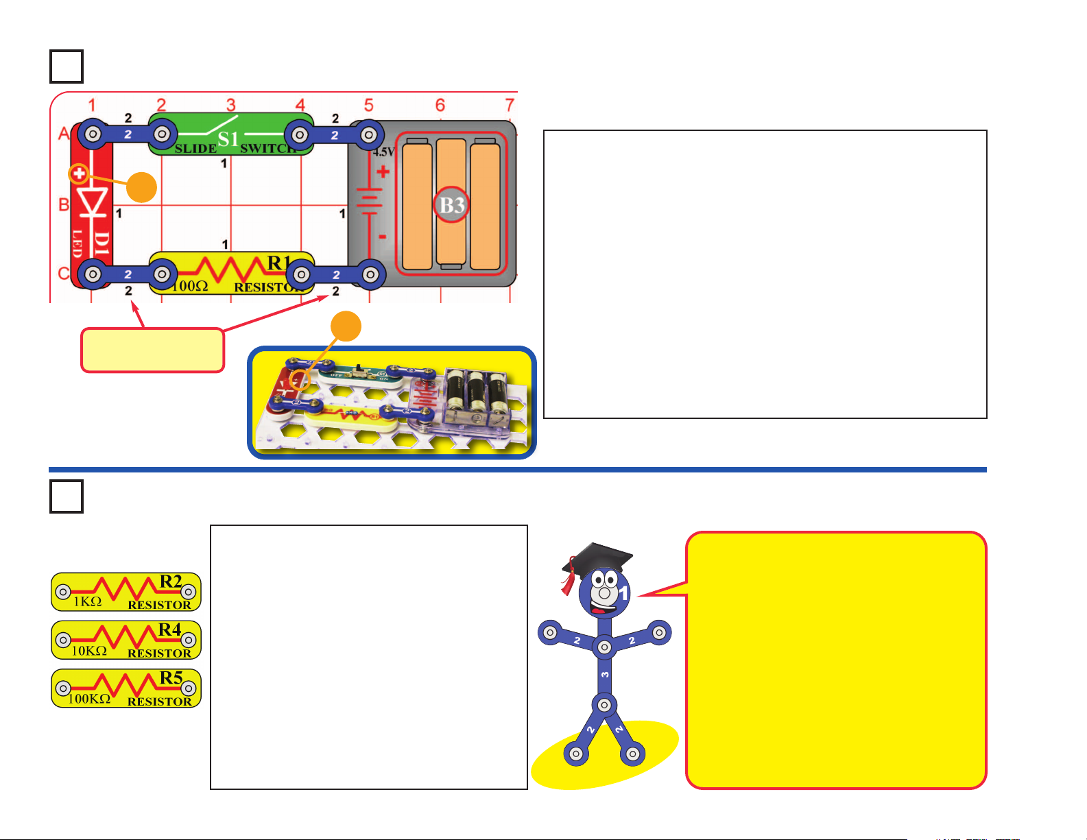
Project A1 Electric Light
Snap Circuits®uses electronic blocks that snap onto a clear plastic
grid to build different circuits. These blocks have different colors
and numbers on them so that you can easily identify them.
Build the circuit shown on the left by placing all the parts with a
black 1 next to them on the board first. Then, assemble parts
marked with a 2. Install three (3) “AA” batteries (not included) into
the battery holder (B3) if you have not done so already.
When you turn on the slide switch (S1), current flows from the
batteries through the switch, red LED (D1), and 100W resistor (R1),
and back to the batteries. Turning on the switch completes the
circuit. When the switch is off, the current can no longer flow back
to the battery, so the red LED goes out.
The red LED is just like the ones used in electronic products
throughout your home.
+
Placement Level
Numbers
+
Use the circuit built in project A1, but replace the
100W resistor (R1) with the 1kW resistor (R2). The
circuit works the same, but the red LED (D1) will
not be as bright.
Now replace the 1kW resistor with the 10kW
resistor (R4). The LED will be dim now.
Now replace the 10kW resistor (R4) with the 100kW
resistor (R5). The 100kW has very high resistance,
so you may not see any light from the LED.
Take the circuit into a really dark room or curl your
fingers around the LED to block the surrounding
light. Now you see that the LED is on, though very
dim.
Project A2 Controlling Electricity
Snappy says resistors are used to control or
limit the flow of electricity in a circuit. Higher
resistor values reduce the flow of electricity in a
circuit.
In this circuit, the resistors are used to adjust the
LED brightness, to limit the current so the
batteries last longer, and to protect the LED
from being damaged by the batteries.
What is Resistance? Take your hands and rub
them together very fast. Your hands should feel
warm. The friction between your hands converts
your effort into heat. Resistance is the electrical
friction between an electric current and the
material it is flowing through.
Page 13
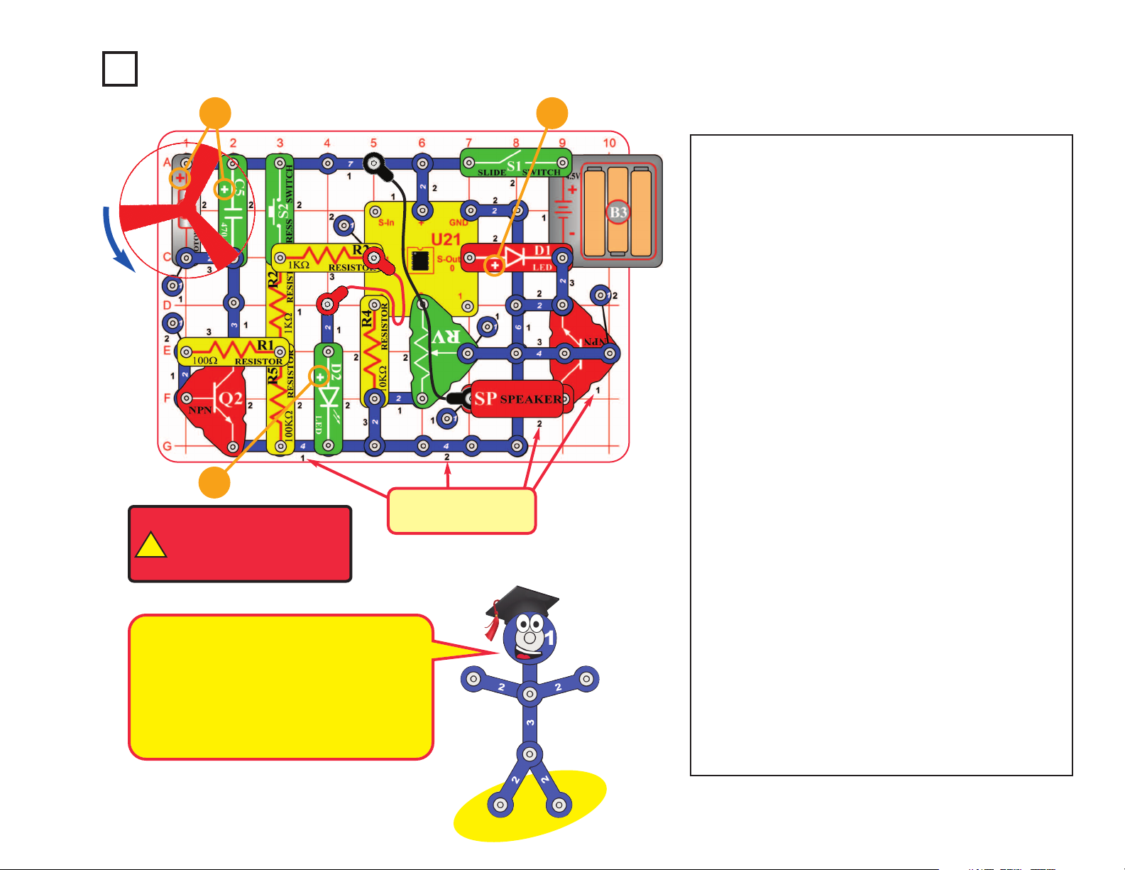
Note: This circuit requires program Electronic Brain
to be in microcontroller U21’s memory. This is loaded
into U21 at the Snap Circuits
®
factory and should still
be there, unless you already reprogrammed it. If it has
been reprogrammed, you must use project B1 (on
page 29) to load program Electronic Brain back into
U21 before building this circuit.
Snap Circuits
®
uses electronic blocks that snap onto
a clear plastic grid to build different circuits. These
blocks have different colors and numbers on them so
that you can easily identify them.
Build the circuit shown above by placing all the parts
with a black 1 next to them on the board first. Then,
assemble parts marked with a 2. Then, assemble
parts marked with a 3. Install three (3) “AA” batteries
(not included) into the battery holder (B3) if you have
not done so already.
Turn on slide switch (S1) and wait for the red LED
(D1) to come on. Push the press switch (S2) and hold
it down until music starts. Set the lever on the
adjustable resistor (RV) for best sound. The motor
(M1) will spin while you push S2, and then will follow
the music as it plays. The red & green LEDs (D1 &
D2) will blink in time with the music. The fan blade is
not necessary and may be removed.
To change the song, push and release S2, then push
it again but hold it down until music starts. For more
songs, turn S1 off and on, slowly push and release
S2 four times, then push and hold down S2 until
music starts.
If you flip the motor around then the fan will rise into
the air like a flying saucer.
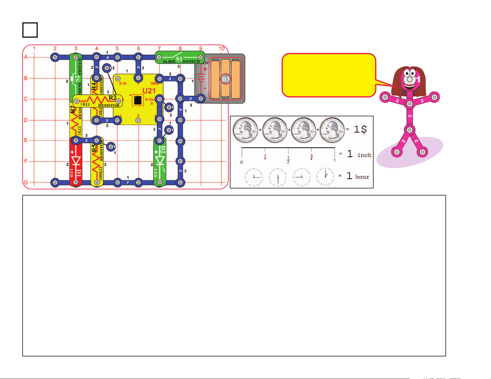
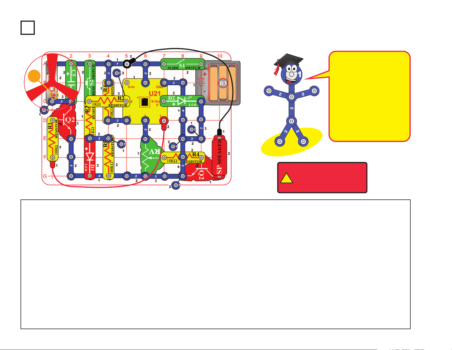
Project A3 Dancing Motor
Placement Level
Numbers
-12-
+
!
WARNING: Moving parts.
Do not touch the fan or
motor during operation. Do
not lean over the motor.
+
This complex circuit is pictured on the front
cover, use that as a guide to help build it.
The program in the microcontroller IC (U21)
controls power to the motor (M1), flashes the
LED (D2), and sends music to the speaker
(SP). The microcontroller is like an electronic
brain running the circuit.
+
Page 14
Project A4 Electronic Counter
Note: This circuit requires
program Electronic Brain to be in
microcontroller U21’s memory.
This is loaded into U21 at the
Snap Circuits
®
factory and should
still be there, unless you already
reprogrammed it. If it has been
reprogrammed, you must use
project B1 (on page 29) to load
program Electronic Brain back into
U21 before building this circuit.
The circuit will count how many
times you press switch S2, then
announce the answer by flashing
LEDs.
Turn on slide switch (S1) and
wait a moment for the green LED
(D2) to come on. Slowly press
switch S2 up to 255 times; the
red LED (D1) flashes each time.
Then wait 10 seconds.
After 10 seconds, the
microcontroller (U21) recognizes that it is time to display the
count. The green LED will turn
off, and then the green & red
LEDs will flash based on the
number of S2 presses. The
green LED will flash first and
each flash counts as 4, then the
red LED will flash and each flash
counts as 1.
For example, if you pressed S2
14 times, the green LED will
flash 3 times (representing 12,
since each counts as 4) and the
red LED will flash 2 times (12 + 2
= 14).
When the microcontroller
finishes displaying the count, the
green LED will stay on, indicating
the microcontroller is ready for
you to press S2 more.
The total is cumulative, and so
includes earlier presses in
counting mode. Turn slide switch
S1 off and on to reset the count
to zero.
When pressing S2 to count, do
not press it rapidly on and off, or
the microcontroller may miss
counts. The red LED should blink
after each count.
Part B: 64 second timer
Turn slide switch S1 off and on
to reset the circuit, and wait for
the green LED to come on. Push
press switch S2 and hold it down
until the green LED turns off.
After a short pause, the red LED
will come on and stay on for
about 64 seconds.
-13-
We measure many things in
quarters. This picture shows
only a few of them. How many
more can you think of that uses
a system like this?
Page 15
Turn off the slide switch (S1). Use the circuit from the preceding
project, but add parts to it so it matches the one shown here.
Set the lever on the adjustable resistor (RV) to the middle.
Turn on the slide switch (S1), and wait a moment for the green
LED (D2) to come on. Slowly press the press switch (S2) six
times, then press it again but hold it down until music starts. The
red & green LEDs blink in time as a song plays. You can adjust
the sound volume using the lever on the adjustable resistor. The
green LED will stay on when the song is finished.
The microcontroller can produce other tunes. Push the press
switch several times (not six times), and then hold it down until
an alarm plays. The green LED will come on when the alarm is
finished.
You can still use the circuit as a counter like in the preceding
project. To count, press switch S2 several times then wait 10
seconds (don’t hold S2 down). The LEDs will display the count
as before, without music.
Project A5 Adding Sound to the Counter
Project A6 Daylight Alarm Clock
Note: This circuit requires program Electronic Brain to be in microcontroller U21’s
memory. This is loaded into U21 at the Snap Circuits®factory and should still be there,
unless you already reprogrammed it. If it has been reprogrammed, you must use project
B1 to load program Electronic Brain back into U21 before building this circuit.
-14-
Use the preceding circuit, but replace the press switch (S2) with
the photoresistor (RP). Place the circuit in a dark room and turn on
the slide switch (S1). The green LED (D2) will come on, indicating
the circuit is working.
When a room light is turned on for more than 10 seconds, or
sunlight makes the room bright, an alarm will sound. The warning
will repeat approximately every minute until the slide switch is
turned off or the
room is made
dark again.
In darkness, the
photoresistor has high
resistance, like a switch
that is turned off. When
light shines on it, the
photoresistor has much
lower resistance, like a
switch that is turned on.
Page 16
Use the circuit from project A5, but replace the press switch (S2)
with the 100W resistor (R1). Place a business card or old
playing card under one end of the 100W resistor, as shown.
Tie a fine black trigger thread on the card and the other end of
the thread to a fixed object in the room. Make sure the trigger
thread stretches across a walk path or in front of a door that will
catch the trigger thread when opened. Turn on the slide switch
(S1). The green LED will come on indicating the alarm is active.
When an intruder trips on the trigger thread, the red light will
come on for a few seconds and then the alarm will sound. The
warning will repeat every minute until the slide switch is turned
off or the card is placed back under the 100W resistor. You can
adjust the sound volume using the lever on the adjustable
resistor (RV).
Note: After the circuit has been on for several minutes without
being triggered by an intruder, the green LED will turn off. Don’t
worry, your alarm circuit is still working. The software running
the microcontroller (U21) has a shutdown feature, which
preserves battery life when there isn’t much happening. The
microcontroller is sleeping, but it will wake up if an intruder
triggers the alarm. Turn off the slide switch (S1) to turn off the
circuit completely.
Note: This circuit requires program Electronic Brain to be in
microcontroller U21’s memory. This is loaded into U21 at the Snap
Circuits
®
factory and should still be there, unless you already
reprogrammed it. If it has been reprogrammed, you must use project
B1 to load program Electronic Brain back into U21 before building this
circuit.
Project A7 Intruder Alarm
Trigger Thread
-15-
The green LED uses about 20mA
of electricity when it is lit. This isn’t
much, but it will drain the batteries
after several days when it is left
on for 24 hours a day. Batterypreserving shutdown modes are
an important feature of microcontrollers.
Page 17
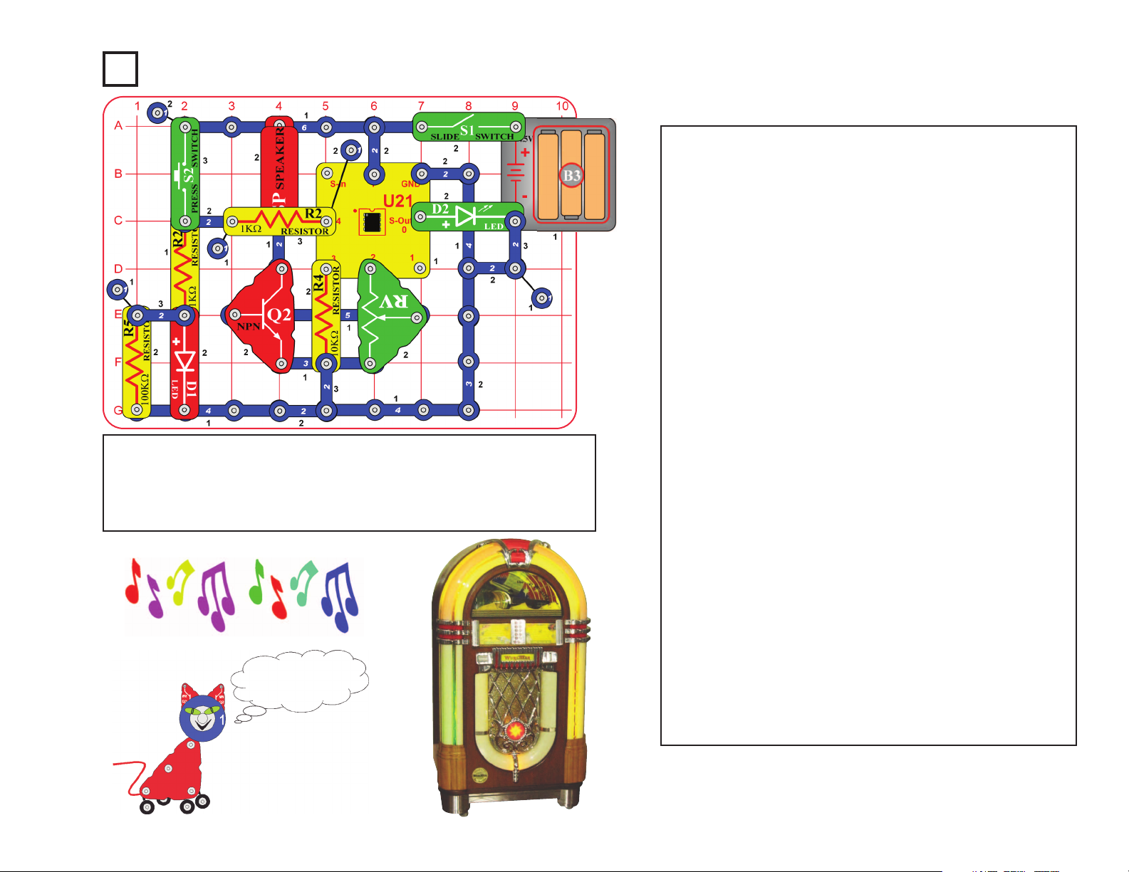
Set the lever on the adjustable resistor (RV) to the middle.
Turn on the slide switch (S1), and wait a moment for the
green LED (D2) to come on. Push the press switch (S2)
and hold it down until music starts. The red & green LEDs
blink in time as a song plays. You can adjust the sound
volume using the lever on the adjustable resistor. The
green LED will stay on when the song is finished.
The microcontroller (U21) contains four songs that are
built into memory and cannot be erased. Each of these
can be programmed to play and flash lights. The
machines that play songs on command are called
“jukeboxes”. A jukebox is a partially automated musicplaying device, usually a coin-operated machine, that can
play specially selected songs from self-contained media.
You just made a simple jukebox!
Select a song to play when the green LED is on and not
flashing. S2 presses are cumulative, unless you turn the
slide switch on and off between songs.
1) Press and hold down S2 to play “Birthday Song”.
2) Press S2 once, then press it again and hold it down
for “Jingle Bells”.
3) Press S2 twice, then press it again and hold it down
for “Silent Night”.
4) Press S2 three times, then press it again and hold it
down for “Rudolph the Red Nose Reindeer”.
5) Press S2 four times, then press it again and hold it
down for all of the above songs in reverse order.
6) Press S2 five or more times, then press it again and
hold it down to play another familiar song.
Project A8 Jukebox
CAN YOU PLAY
THREE BLIND MICE?
-16-
Note: This circuit requires program Electronic Brain to be in microcontroller
U21’s memory. This is loaded into U21 at the Snap Circuits
®
factory and
should still be there, unless you already reprogrammed it. If it has been
reprogrammed, you must use project B1 to load program Electronic Brain
back into U21 before building this circuit.
Page 18
Project A9 Counting To The Stars
Note: This circuit requires program Electronic
Brain to be in microcontroller U21’s memory.
This is loaded into U21 at the Snap Circuits
®
factory and should still be there, unless you
already reprogrammed it. If it has been
reprogrammed, you must use project B1 to load
program Electronic Brain back into U21 before
building this circuit.
The circuit will count how many times you
press switch S2, play some music, and then
spin the fan for a duration based on how many
times you pressed the switch.
Part A. Turn on slide switch (S1) and wait a
moment for the green LED (D2) to come on.
Press switch S2 once; the red LED (D1)
flashes. Wait for the green LED (D2) to turn off
(about 10 seconds after you press S2). When
the green LED comes back on, press and hold
down S2 until music starts. The motor (M1) will
spin for 1/4 second and stop. The green LED
will come back on, indicating the time has been
reset.
Part B. Now press switch S2 three times, and
wait for the green LED to go off. The red LED
will flash three times, indicating the motor will
spin for 3/4 seconds. Press and hold down
switch S2 until the music starts. The motor
should spin for 3/4 seconds, and the fan may
rise into the air.
Part C. Now press switch S2 ten times, and
wait for the green LED to go off. The green
LED will flash twice and the red LED will flash
twice. Each green flash equals 1 second and
each red flash equals 1/4 second, so the motor
should spin for 2 and 1/2 seconds. Press and
hold down switch S2 until the music starts. The
motor should spin for 2 and 1/2 seconds, and
the fan will rise into the air.
Part D. For each time you push the switch, the
motor will spin for 1/4 second. Press switch S2
up to fifty times, and wait for the green LED to
go off. The green & red LEDs will flash based
on the motor spin time you entered; each green
flash equals 1 second and each red flash
equals 1/4 second. Press and hold down switch
S2 until the music starts. The motor should spin
for the duration you entered; if the time is long
enough then the fan will rise into the air.
-17-
!
WARNING: Moving parts.
Do not touch the fan or
motor during operation. Do
not lean over the motor.
This complex circuit is
pictured on the box cover, use
that as a guide to help build it.
The program in the
microcontroller IC (U21)
controls power to the motor
(M1), flashes the LEDs (D1 &
D2), and sends music to the
speaker (SP).
The microcontroller is like an
electronic brain running the
circuit.
+
Page 19
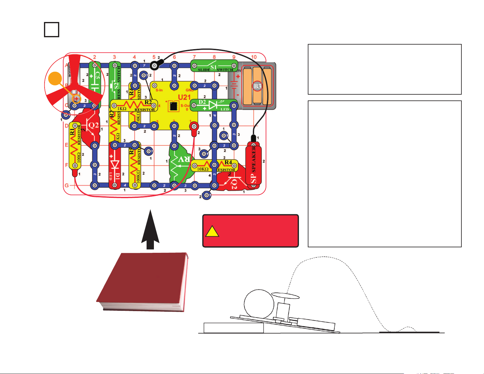
Project A10 Angles and Distance
Use the same circuit as project A9, but place a
book or other object under the base to create a
launch angle as shown. Place a piece of paper or
short box on the floor approximately three feet in
front of the snap circuit base. This paper/box is
the target area landing zone.
Turn on slide switch (S1) and wait a moment for
the green LED (D2) to come on. Push the press
switch (S2) as many times as desired, then press
it again and hold it down. When an alarm starts,
release S2. When the alarm stops, the motor (M1)
should spin for a while, and then the fan should
launch toward the target. Repeat, pressing S2
more or less times. The more times you press S2,
the higher/farther the fan should fly. See who can
land the fan on the paper/box with the fewest
launches.
BOOK CIRCUIT TARGET
!
WARNING: Moving parts.
Do not touch the fan or
motor during operation. Do
not lean over the motor.
Note: This circuit requires program Electronic Brain to
be in microcontroller U21’s memory. This is loaded into
U21 at the Snap Circuits
®
factory and should still be
there, unless you already reprogrammed it. If it has been
reprogrammed, you must use project B1 to load program
Electronic Brain back into U21 before building this circuit.
-18-
+
Page 20
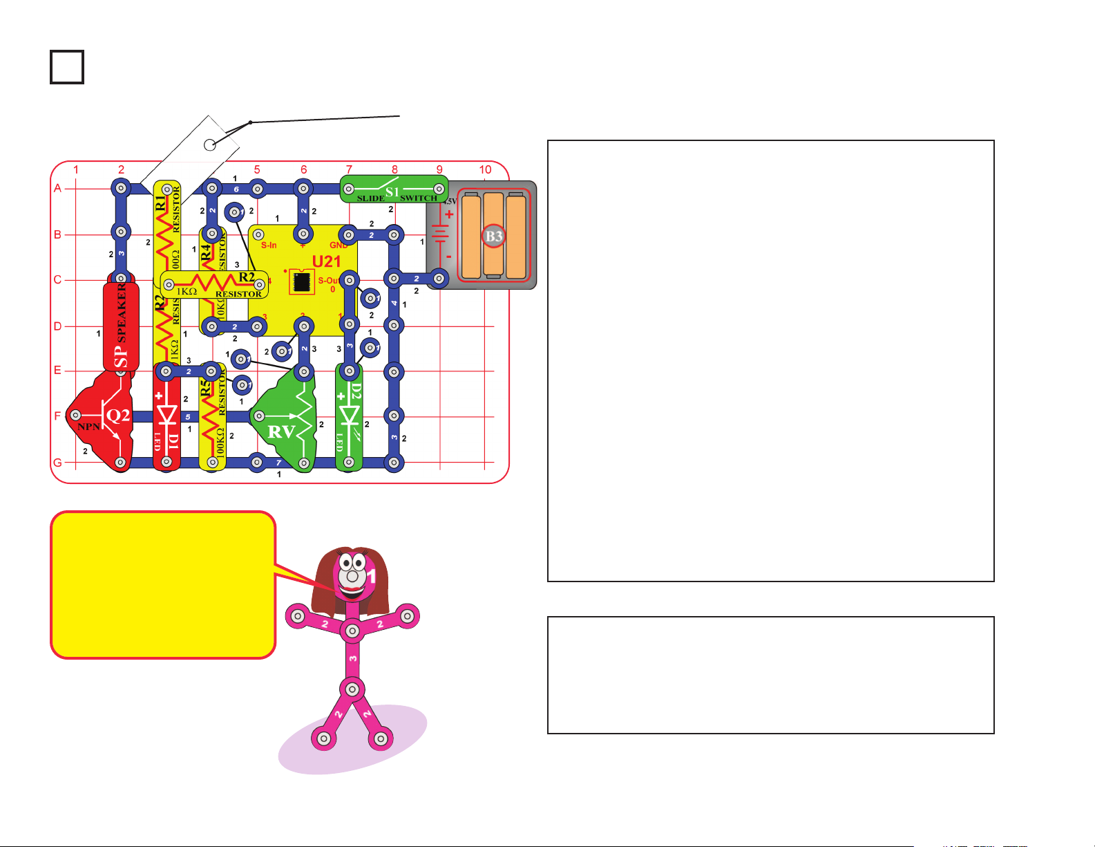
Project A11
Build the circuit, leaving
one end of the black
jumper wire unconnected.
Turn on the switch (S1).
One LED (D1 or D2) will
be on, the other off.
Alternately touch the
loose end of the black
jumper wire to the snaps
marked “A” and “B” in the
drawing. When you do,
both LEDs change
between on and off. One
LED “flips” on and the
other “flops” off.
Flip-Flop
Project A12
Build the circuit, turn on the slide switch (S1), and push the press
switch (S2). The red LED (D1) will be on for a little while. Push
the press switch again to turn the LED back on. Move the lever
on the adjustable resistor (RV) to adjust how long the LED stays
on for.
Adjustable Light Timer
-19-
This circuit is known as a “flip-flop” due to the way
it operates. Variations of this circuit form one of
the basic building blocks for computers. This
circuit can be thought of as a memory because it
only changes states when you tell it to, it
“remembers” what you told it to do, even though
you removed the loose wire. By combining
several of these circuits, you can remember a
letter or number. A typical computer has
thousands of flip-flops, in miniaturized form.
Page 21

Project A13
Build the circuit, turn on the slide switch (S1), and push the
press switch (S2). The LEDs (D1 & D2) light for a while and
then turn off. Push the press switch again to turn the LEDs
back on. The brighter the light shining into the photoresistor,
the faster the LEDs turn off.
The adjustable resistor is used as a fixed resistor in this circuit,
so moving its lever won’t change anything.
Light Sensitive Timer
Project A14
You need a flashlight for this project. Build the circuit, and note
that there is a 3-snap wire across base grid locations F3-F5,
which is under the left NPN transistor (Q2). Turn on the slide
switch (S1).
Take the circuit into a dark room. Shine the flashlight into the
photoresistor (RP), and carefully move the lever on the
adjustable resistor (RV) until the red LED (D1) lights. You will use
the flashlight as a gun, and “shoot” at the photoresistor.
Keep the room dark and move away from the circuit. “Shoot” your
flashlight by quickly switching it on and off. Try to hit the
photoresistor with the light beam from the flashlight. When you
are on target, the red LED will light. You can have contests with
your friends to see who has the best aim.
Shot in the Dark
-20-
Notice how the green LED turns off a little faster than
the red LED. The LEDs are made from different
materials, and the red LED is a little more sensitive to
electricity than the green LED.
Page 22

Project A17
Build the circuit, but leave the ends of the red and black jumper wires
unconnected at first.
When you place a metal paper clip (not included) across the loose ends
of the jumper wires as shown, current flows from the batteries through
the resistor, through the LED, and back to the battery. The paper clip
completes the circuit and current flows through the LED. Place your
fingers across the terminals and the LED does not light. Your body is
too high of a resistance to allow enough current to flow to light the LED.
If the voltage, which is electrical pressure, was higher, current could be
pushed through your fingers and the LED would light. This detector can
be used to see if materials like plastic, wood, cloth, aluminum, or paper
are a good conductor or a poor conductor.
Conduction Detector
Project A15
Microphone Control
In this circuit, blowing
on the microphone (X1)
changes the LED (D1)
brightness.
The resistance of the
microphone changes
when you blow on it.
You can replace the
microphone with one of
the resistors to see
what resistor value it is
closest to.
Project A16
Adjustable Brightness
In this circuit, changing
the adjustable resistor
(RV) setting changes
the brightness of the
LED (D1).
The lever on RV
adjusts how much
resistive material the
electric current flows
through.
-21-
+
Page 23

Turn on the circuit using the slide switch (S1) and move the
adjustable resistor’s (RV) control lever around to adjust the
brightness of the LEDs (D1 & D2). When the adjustable resistor
is set to one side, that side will have low resistance and its LED
will be bright (assuming the switch on that side is ON) while the
other LED will be dim or OFF.
Project A19
Parallel Resistors
Project A20
Series Resistors
Project A18 Slider
-22-
Turn on either or both
switches (S1 & S2) and
compare the LED (D1)
brightness.
This circuit has the 100W
resistor (R1) and 1kW
resistor (R2) arranged in
parallel. The smaller
100W resistor controls the
brightness in this
arrangement.
You can replace either
resistor with any other
resistor and compare the
effect.
Turn on either or both switches
(S1 & S2) and compare the
LED (D1) brightness.
This circuit has the 100W
resistor (R1), the 1kW resistor
(R2), and the photoresistor
(RP) arranged in series. The
switches are used to bypass
the larger resistors. The
largest resistor controls the
brightness in this
arrangement. The resistance
of the photoresistor will be
much higher than the others,
unless the light is very bright.
Page 24

Project #A21
Push the press switch (S2) until
the motor reaches full speed, then
release it. The fan blade should
rise and float through the air like a
flying saucer. Be careful not to
look directly down on fan blade
when it is spinning.
If the fan doesn’t fly off, then press
the switch several times rapidly
when it is at full speed. The motor
spins faster when the batteries are
new.
Flying Saucer
Project #A22
Build the circuit, turn on the slide switch (S1), and adjust the
amount of light shining on the photoresistor (RP). Compare the
brightness of the red and green LEDs (D1 & D2) as you change
the light on the photoresistor.
Transistor
!
WARNING: Moving parts. Do not
touch the fan or motor during operation.
Do not lean over the motor. Fan may
not rise until switch is released.
-23-
The air is being blown down
through the blade and the
motor rotation locks the fan
on the shaft. When the
motor is turned off, the blade
unlocks from the shaft and is
free to act as a propeller and
fly through the air. If speed
of rotation is too slow, the fan
will remain on the motor
shaft because it does not
have enough lift to propel it.
The resistance of the photoresistor decreases
as more light shines on it, so the red LED gets
brighter as the light is increased. The
transistor (Q2) amplifies the current through
the photoresistor and red LED, to produce a
larger current through the green LED, making
it brighter than the red LED.
+
Page 25

This circuit shows how a capacitor can store
and release electrical energy.
Turn on the slide switch (S1) for a few
seconds, then turn it off. The green LED (D2)
flashes dimly for a moment, and then goes
dark as the batteries (B3) charge up the
470mF capacitor (C5). The capacitor is storing
electrical energy, as if it were a small battery.
Now press the press switch (S2) for a few
seconds. The red LED (D1) is initially bright
but goes dim as the capacitor discharges itself
through it.
The capacitor value (470mF) sets how much
electricity can be stored in it, and the resistor
value (1kW) sets how quickly that electricity
can be stored or released.
Capacitor BatteryProject A23
Turn on the slide (S1) and blow into the microphone (X1). The
red LED(D1) will flicker and you hear static from the speaker
(SP).
Talk loudly into the microphone. You can hear your voice on the
speaker, though it may be badly distorted.
Blow Off Sound
Project A24
-24-
Capacitors store electricity in an electric
field between metal plates, with a small
separation between them. This electric
field is similar to the magnetic field of a
magnet. Compared to batteries (which
store energy as separated chemicals),
capacitors can only store small amounts
of energy, but they can release it quickly,
can be made in very small sizes, and are
inexpensive.
Page 26

Project #A25 Capacitor Photo Control
Project #A26
Modify the preceding circuit
to match the one shown
here. It works the same way,
but the red LED (D1) stays
on longer and very little light
is needed on the
photoresistor (RP).
Capacitor Photo Control
with Slow Shut-off
Adding a second transistor makes the
circuit more sensitive to current from the
capacitor and photoresistor, so the LED
stays on longer. Transistors allow very
small currents to control large currents.
-25-
Turn on the slide switch (S1)
and press the press switch
(S2). If there is light on the
photoresistor (RP), then the
LED (D1) will stay on for a
long time after you release
the press switch.
The energy stored in the 470mF capacitor
(C5) keeps the controlling current to the
NPN transistor (Q2) on even though the
press switch was turned off. If it is dark,
the high resistance of the photoresistor
shuts off the current to the transistor.
Page 27

Project #A27
Turn on the slide switch (S1). If there is light on the photoresistor
(RP) then the LEDs (D1 & D2) will be on. Cover the photoresistor
to switch off the LEDs and switch on the motor (M1).
Photo Switcher
Project #A28
Turn on the slide switch (S1) and blow into the microphone
(X1). The red LED(D1) will flicker and you hear static from
the speaker (SP).
Talk loudly into the microphone. You can hear your voice
on the speaker, though it may be badly distorted.
Blow On Sound
!
WARNING: Moving parts.
Do not touch the fan or
motor during operation. Do
not lean over the motor.
-26-
Page 28

Project #A29
Set the adjustable resistor (RV) control lever
to the top and turn on the slide switch (S1).
Talk or blow into the microphone (X1). You
should hear your voice on the speaker (SP)
and the green LED (D2) flashes.
Your voice will not be very loud and may be
badly distorted. Adjust the adjustable resistor
lever for the best sound.
Scratchy Amplifier
-27-
Project A30
Build the circuit, turn on the slide switch (S1), and push the press
switch (S2). The red LED (D1) will be on for a while and then go
off. Push the press switch again to turn the red LED on again.
Use the lever on the adjustable resistor (RV) to control how long
the red LED stays on for.
One Shot
This circuit can be used as a timer. You might use
a circuit like this in a microwave oven. You press
the switch to turn the oven on and have a knob
(like the adjustable resistor) to adjust how long
the oven stays on; it then shuts off automatically.
Page 29

Introduction
The U21 microcontroller IC module (U21) consists of the
microcontroller IC in a socket, and mounted on a Snap Circuits
®
platform. Do not remove the microcontroller from the socket. All
microcontrollers are programmable, but the
microcontroller you are
using has a special programming interface that makes it very easy to
use.
WHAT IS A MICROCONTROLLER?
A microcontroller is a mini computer. It’s a miniaturized circuit that
contains memory, logic, processing, and input/output circuitry.
Microcontrollers are programmed with specific instructions to control
many different devices. Once programmed the microcontroller is
built into a product to make the product more intelligent and easier
to use.
A microcontroller receives input (such sources such as a switch,
microphone, photoresistor, or computer keyboard), processes it and
makes decisions, then controls outputs (such as an LED, speaker,
motor, or computer display) based on the decisions.
For example, a microwave
oven uses a single microcontroller to process
information from the keypad,
display user information on a
display, and control the
turntable motor, light, bell and
cooking time.
One microcontroller can often replace a number of separate parts,
or even a number of complete electronic circuits.
Microcontrollers are used in household
appliances, alarm systems, medical
equipment, vehicle subsystems,
musical instruments, and
electronic instrumentation.
Most cars contain many
micro-controllers, using
them for engine
management, remote
locking, and other functions.
Programs are stored in memory as a series of numbers. A program
is executed by moving information (stored as numbers) between
places, such as activity registers, input/output ports, and memory.
Computers cannot do complex mathematics, but they can perform
simple math very quickly, and programming tricks allow complex
calculations to be performed as a series of simple ones.
Microcontroller IC module (U21)
8-pin socket on Snap Circuits
®
platform
Microcontroller IC
+
PART B - Microcontroller Projects
-28-
=
Page 30

Project B1
-29-
Installing Software and Programming Cable
Windows®XP (or later) or Mac OSX
10.4 (or later) or Linux x386 with
GTK2.8 (or later), 512MB RAM,
500MB of hard-disk space, USB
port, and an internet connection.
Blinker (Programming the Microcontroller)
This project explains the procedure for re-programming the
microcontroller (U21). The microcontroller can be re-
programmed in ANY circuit that uses it (including projects A3-
A10),
by attaching the programming cable to it. When you initiate
a new program download, any program currently running in the
microcontroller is interrupted. When a new program download is
complete, the new program will begin running.
The programming cable is needed to download new programs to
the microcontroller, and to allow some programs to transfer
information to/from the computer’s display. The programming cable
may be removed from a circuit when not being used.
Requirements for
your computer
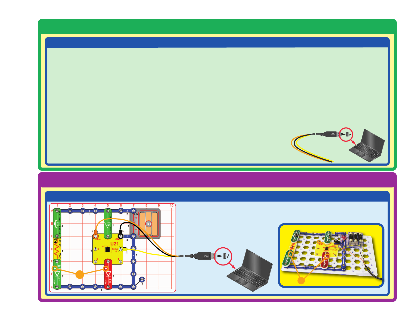
STEP 1
STEP 2 (Windows Users)
Insert the Programming Cable into a
USB port on your computer. The
Programming Cable will automatically
configure itself. If you have problems with
configuration then contact ELENCO
®
.
Programming Cable
Download the AXEpad for Snap Circuits®XPTMsoftware from the appropriate link below,
then follow the instructions to install it.
Windows - http://www.elenco.com/downloads/WinAXEpad.zip
Mac - http://www.elenco.com/downloads/macaxepad.app.tar.gz
Linux - http://www.elenco.com/downloads/linaxepad.tar.gz
Go to the download and extract the compressed fles. Open the extracted files folder
and run the appropriate file for your system (such as winaxepad.exe for Windows users,
and MacAXEpad.app.tar for Mac users).
Note: the programming cable should NOT be connected during this installation. Mac
users may need to change their security preferences to allow installation of applications
not purchased through the App Store or authenticated by Apple. Contact ELENCO
®
if
you have questions or problems with the installation.
Page 31
How to Use AXEpad
-30-
Installing Software and Programming Cable
STEP 2 (Mac Users)
STEP 3
Build the circuit on the left, and attach the programming cable to it as shown.
Turn on the slide switch (S1).
+
+
1. Install USB driver software (Do not insert the cable yet!).
Insert the CD provided into your computer and open the Mac
USB Driver folder.
If your Mac has an Intel processor:
Click on the “Mac_intel.dmg.zip” file and follow the
instructions that appear on the dialog box. You may also
access this file online at the following address:
http://www.rev-ed.co.uk/software/axe027_mac_intel.dmg.zip
For older Macs:
Click on the “Mac_powerpc.dmg.zip” file and follow the
instructions that appear on the dialog box. You may also
access this file online at the following address:
http://www.rev-ed.co.uk/software/axe027_mac_powerpc.dmg.zip
2. Once installation is complete, the computer will need to be
rebooted.
3.
After the computer has rebooted, plug in the Programming Cable.
4.
Open MacAXEpad. Go to View > Options > Port and click on
the “USB Setup” button. A dialog box will open with the serial
number for the cable that will look like this: /dev/tty.usbserialxxxxxxxx – where xxxxxxxx is the serial number of the cable
(e.g. FTT6KHLX). Copy this number down on a piece of
paper (note: this number is case sensitive), close the dialog
box, and enter in the correct serial number into the white box.
Click OK to close the dialog box.
Your cable should now work with the MacAXEpad program.
For clarifications, visual
aids, and updates,
please visit our website:
www.snapcircuits.net
Page 32

-31-
How to Use AXEpad
STEP 4
Double-click the AXEpad for Snap Circuits
®
XPTMicon on your desktop (unless you directed
that it be installed somewhere else) to start the
AXEpad for Snap Circuits
®XPTM
software. The
software screen should look similar to the one shown
below. (Note for Mac users: The software screen will not
have any icons along the top.)
STEP 5
The program you chose will appear in the editor space.
The procedure for programming the microcontroller for the other
projects is the same as you are doing here, except the program
name will be different.
Introductory projects A3-A10 require the program Electronic Brain to
be loaded in the microcontroller. This program was loaded into the
microcontroller at our factory. If the microcontroller has been
reprogrammed, then you will need to reload Electronic Brain to do
the introductory projects.
Select File, then Open Snap Circuits Samples ...,
and then pick the program you want to download to
the microcontroller. Choose the Blinker program for
the circuit you are building now.
Any time a task needs to be performed over and
over again, a microprocessor or computer on a
chip should be considered to help perform the task.
Page 33

-32-
How to Use AXEpad
STEP 6
Click Program to download your program to
the microcontroller. This will interrupt and erase
the program currently in the microcontroller.
(Note for Mac users: Since there is no
Program icon, you must click on the PICAXE
menu tab and select
Program, or simply press
F5 on your keyboard.) A window will open for
the download process, like the one shown here:
Window for Downloading Process
A message will tell you when the new program download is complete, and the new
program will begin running.
If you turn off the microcontroller, the program in it will restart when the microcontroller
is turned back on.
The programming cable may be removed after the program download is finished; it is
usually not needed for running the program. Some Snap Circuits
®XPTM
projects will use
the cable to enter or display information using the computer screen while a program is
running, these will tell you to keep the cable connected after program download.
STEP 7
The Blinker program should now be running in the microcontroller,
and the red LED (D1) should be blinking.
Push the press switch (S2) several times to make the green LED
(D2) blink. Try to make the green LED blink at the same rate as the
red LED. It is probably much easier to let the microcontroller blink
the red LED, rather than blink the green LED by pressing the switch.
TROUBLESHOOTING
If you get an error while trying to download a program,
start the download and then reset the microcontroller
(turn slide switch S1 off and on) just after the words
“Downloading program” are displayed. A running
program will be interrupted by a new download when it
executes a command, but some commands (such as long
pause or wait commands) can take too long to complete,
so the download could be ignored. Resetting the
microcontroller just after initiating a download ensures that
the microcontroller will recognize the new download. If you
still can’t download, use the Advanced Troubleshooting
procedure on page 8.
If you get an error saying the Download Cable cannot
be found: make sure you have the Programming Cable
connected. If this is the first time using your programming
cable, you may need to manually select the
communication port for it. (Note: the Download Cable is
your Programming Cable.) For Windows
®
Computers:
select Options
then Port
then pick a COM port to try
(pick the highest-numbered port first).
Close the Options window and try to
Program again.
If an error message appears,
see Troubleshooting.
Page 34

-33-
OPTIONAL - TO LEARN ABOUT PROGRAMMING
You can edit the program to change
parameters or commands if desired. The
editing procedure is similar to other Windows
®
word processors. You may also type in a
completely new program. To save programs
you have created or modified, use
Save As
under File menu.
Only valid programs (without errors) may be
downloaded, or a downloading error will result.
You can check for errors by clicking the
Syntax box, and then clicking Program.
Syntax also tells you how much memory the
program uses; programs must be of 256 bytes
of memory or less. All Snap Circuits
®XPTM
programs have already been checked for
errors.
Explanations for all the microcontroller
commands, and some basic information about
programming, can be found under the Help menu
at Snap Circuits®XPTM.
Use this file to look up a command you want to
learn about. If you later want to write your own
programs, you’ll need to use this often. Part C - To
Go Further (page 59) has other useful information.
The PICAXE
®
Manual (Parts 1, 2, and 3) has more
detailed explanations of the PICAXE®commands,
and other information about PICAXE
®
products,
however much of this information is not applicable
to Snap Circuits®XPTMand some is very technical.
The Snap Circuits
®XPTM
help file is customized to
your product.
Here is how the program works:
high 2 - this tells the microcontroller to put
an electrical voltage at out put 2 (where
the red LED is connected). This voltage
will light the LED.
pause 1000 - this tells the microcontroller
to pause for 1000 milliseconds, or 1
second, before performing the next
instruction.
low 2 - this tells the microcontroller to turn
off or remove any voltage at output 2. This
will turn off the red LED.
goto main - this tells the microcontroller
to execute the instructions next to “main:”,
which here means repeating the
instruction set. This causes the LED to
turn on and off, blinking continuously.
Information after an apostrophe (‘) symbol is
Comments. Comments are a description of
what the program is doing, to help you
understand and remember it. Comments are
ignored by the microcontroller.
Page 35

Build this circuit and turn on the switch (S1). Load program
Blinkers into the microcontroller using the programming
instructions in project B1. The microcontroller controls the red and
green LEDs (D1 & D2), and alternates turning them on and off.
Now download one of the other Blinkers programs (Blinkers
Together, Blinkers Faster, or Blinkers Uneven) into the
microcontroller using the same procedure as in project B1. The
Blinkers programs change the LEDs’ blinking pattern.
You can download a new program into the microcontroller while
it is running another program; the running program will be
interrupted and the new program started. The programming
cable only needs to be connected while downloading a program
into the microcontroller.
Project B2 Blinkers
Optional:
You can change the blink rate by editing the
PAUSE times in the program, then re-downloading
it to the microcontroller.
The PAUSE time must be a whole number
between 0 and 65535. This is a delay in
milliseconds (1/1000 second) between program
commands. You can change the PAUSE times in
any of the Blinkers programs and see the effect.
Do not change anything else in the program. The
program at right is the Blinkers program.
Only valid programs (without errors) may be
downloaded, or a downloading error will result.
You can check for errors by selecting Syntax.
The microcontroller lets you control the
LEDs in ways that would be difficult to
do using switches or other devices.
-34-
Page 36

-35-
Build this circuit and turn on the switch (S1). Load
program Four Outputs into the microcontroller using the
programming instructions in project B1.
The microcontroller controls four outputs - the speaker,
green LED, red LED, and motor - and turns them on and
off in sequence. Try doing that without a microcontroller!
Now download program Four Outputs Faster or Four
Outputs Together into the microcontroller. The circuit
performs a little differently.
Project B3 Four Outputs
Optional:
You can change the blink rate by editing
the PAUSE times in the program, then redownloading it to the microcontroller. The
PAUSE time must be a whole number
between 0 and 65535. Do not change
anything else in the program. The
program at left is the Four Outputs
program.
Microcontrollers are very flexible
because they let you change what a
circuit does just by reprogramming,
and without changing the actual
components.
+
!
WARNING: Moving parts.
Do not touch the fan or
motor during operation. Do
not lean over the motor.
Page 37

Project B4 Play a Tune
Optional:
You can adjust the tempo of the song by changing the
second number in the Tune command of this program to any
whole number from 1 (fast) to 15 (slow), then re-download.
Do not change anything else in the program.
-36-
The Tune command produces musical
notes (in the form of an electrical
voltage) on output 2.
It is possible to create your own music
using the tune command, but this is not
recommended because the coding
method is complicated and not easy to
use. Programming Editor (a more
advanced version of PICAXE software)
has a Tune Wizard that makes creating
or importing music easy. See page 59 for
more information about Programming
Editor.
Many more tunes are available for your PICAXE®08M microcontroller:
http://www.rev-ed.co.uk/software/tunes1_1.zip (450 tunes)
http://www.rev-ed.co.uk/software/tunes2_1.zip (350 tunes)
http://www.rev-ed.co.uk/software/christmas_1.zip (72 Christmas Songs)
http://www.rev-ed.co.uk/software/tvthemes_1.zip (48 TV & Movie tunes)
http://www.rev-ed.co.uk/software/anthems_1.zip (15 national anthems)
These files must be downloaded and unzipped into a new folder on your computer.
Then they can be downloaded into your microcontroller from that folder.
Build the circuit as shown. Turn on the slide switch (S1). Load
any of the programs whose name starts with “Song-” (such as
Song-PopGoesWeasel) into the microcontroller (U21) using the
programming instructions in project B1. Program Piano can
also be used.
The microcontroller will play a tune and may flash some lights.
Use the lever on the adjustable resistor (RV) to adjust the volume.
Page 38

-37-
The microcontroller can be programmed to produce cute sounds
in different ways. This project demonstrates some of them.
Build the circuit shown; it is simpler than the preceding circuit
but does not have a volume control. Turn on the slide switch (S1).
Load any of the programs listed here into the microcontroller
(U21) using the programming instructions in project B1. The
microcontroller will play a tune and may flash lights. You have a
computer music box!
A. Use program Computer Music Box.
B. Use program Make a Sound.
C. Use program Ascending Sound.
D. Use program Robotic Sounds.
Project B5 Computer Music Box
Optional:
This program plays a song in the
microcontroller’s memory. Change the
0 to a 1, 2, or 3 to change the song.
This program plays a sequence of musical notes. The sequence in
parenthesis is the musical notes (ranging from 0 to 255) and their
durations (all values here are 100, so each note plays for 1 second).
Page 39

This program plays an ascending
sequence of notes for very short
durations, which combine to make
a cute sound. You can change the
110 to any whole number between
0 and 127.
This program plays a sequence of
sounds based on the random
command.
You can change these
zeros to any whole numbers between
0 and 255. You will have lots of fun
seeing how the sounds change when
you change these values.
-38-
Optional:
The Play command produces a musical tune (in the
form of an electrical voltage) on output 2.
The
Wait command tells the microcontroller to delay
before performing the next instruction.
The
Sound command produces a sequence of musical
tones or noise sounds (in the form of electrical voltages)
on an output pin.
The
If command makes decisions.
The Random command generates a “random”
sequence of numbers that isn’t really random.
Microcontrollers perform mathematics to generate
random numbers, so the sequence produced will be the
same each time unless the starting point is changed.
Details on how these commands work can be found
under the Help menu at Snap Circuits
®XPTM
.
Page 40

-39-
Project B6 Random Sounds
Build the circuit as shown. Turn on the slide switch (S1). Load
program Random Sounds or program Random Robotic Sounds
into the microcontroller (U21) using the programming instructions
in project B1. Push the press switch (S2) and listen to the sounds.
Optional:
These programs use the Random
command to make cute sounds.
The random command produces
a sequence of numbers that is
always the same, but we make the
result seem random by changing
the start point.
Here the random command is
called repeatedly in a loop, while
waiting for S2 to be pressed. The
number of loops between switch
pushes varies, making the result
seem random.
Page 41

Project B7 Sloppy Switches
Optional:
-40-
The program tells the microcontroller to
monitor input pin 3, where the press
switch is connected. Every time the
switch is pressed, the microcontroller is
to toggle (turn on or off) the red LED
(D1) at output pin 0.
The input pins on the microcontroller
have two states - 1 (on, or high, or
having strong voltage) or 0 (off, or low,
or having no voltage). If the electrical
signal is somewhere between these, the
microcontroller may get confused.
Build the circuit as shown. Turn on the slide switch (S1). Load program
Sloppy Switches into the microcontroller (U21) using the programming
instructions in project B1.
Push the press switch (S2) several times. Each time you press it the red LED
(D1) should toggle (turn on or off). But sometimes it will just flicker and not
change. Press the switch enough times to see this happen.
This effect makes it appear the switch isn’t working, or the microcontroller
isn’t watching it carefully enough. Do you know what is really happening?
Most switches use a metal contact that snaps into place. This action may
cause the switch to bounce and produce “switch noise” when it is closed. This
can cause equipment to think the switch was pressed more than once, and
so cause improper operation.
Page 42

-41-
Use the same circuit as project B7. Load the program
Bounceless Switches into the microcontroller (U21)
using the programming instructions in project B1. The
circuit works the same, except the LED will toggle every
time the switch is pressed. The “switch bounce” problem
has been fixed.
Part B. Try swapping the positions of the press switch
(S2) and the 1kW resistor (R2). Now the red LED
changes when the press switch is released instead of
when the switch is pushed.
Sometimes hardware cannot be changed but the
software (program) can. How could you change the
flowchart program to make the LED toggle when the
press switch is released using the original circuit?
Snappy knows how.
Project B8 Bounceless Switches
Optional:
The “switch bounce” problem
was fixed here by adding a
0.1 second pause before the
microcontroller checks if the
switch was pressed.
To make the LED toggle
when the press switch is
released, change the input
pin 3 tests (from 1 to 0 or
from 0 to 1).
Page 43

As it is, this program will not work
properly. To fix it, modify the program to
subtract 49 from variable b2 in line 7
,
instead of subtracting 1. The serin command
in line 6 gives a coded value for variable b2
(called its ASCII code), because you could
have typed a letter instead of a number.
Alternatively, you could place case numbers
0-3 in lines 13, 15, 17, and 19 in quotation
marks (“0”, “1”, “2”, and “3”).
Project B9
Jukebox with Terminal
-42-
Build the circuit as shown. Turn on the slide
switch (S1). Load program Jukebox with
Terminal and
modify it as described below.
Load the modified program into the
microcontroller (U21) using the programming
instructions in project B1.
After program is downloaded, move the
orange jumper wire from the S-In snap to the
1 snap, as shown. Press the F8 key or select
Terminal under the PICAXE menu to open a
terminal window for communication with the
microcontroller, set the baud rate to 2400,
and select Refresh. Turn the slide switch (S1)
off and on to reset the microcontroller. Follow
the instructions in the terminal Input Buffer
window to use your “jukebox”.
Song numbers:
1 = Happy Birthday
2 = Jingle Bells
3 = Silent Night
4 = Rudolph
Optional:
(for two-way
communication
with terminal)
(for download)
This program uses the serin
and serout commands to
send information between the
computer screen and the
microcontroller. Details on
how these commands work
can be found under the Help
menu at Snap Circuits
®XPTM
.
Page 44
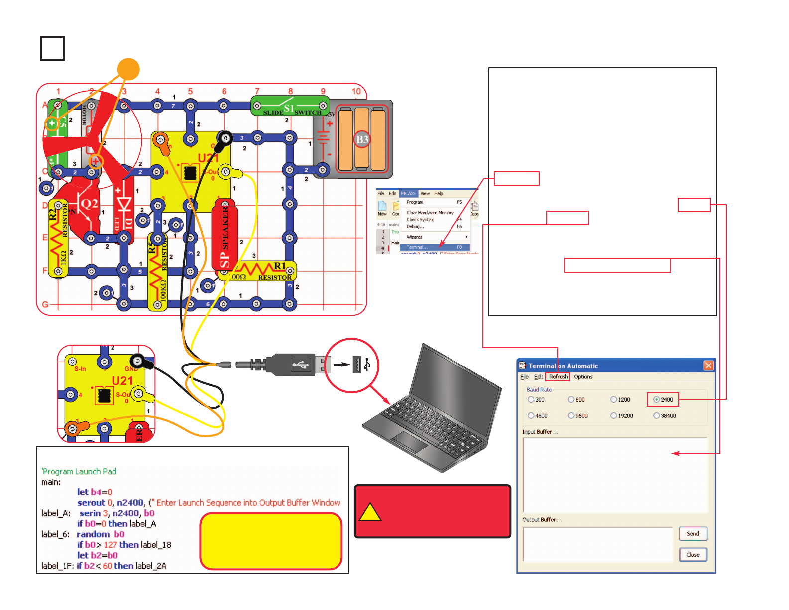
-43-
(for two-way communication
with terminal)
Project B10 Launch Pad
Build the circuit as shown. Turn on the slide
switch (S1). Load program Launch Pad into
the microcontroller (U21) using the
programming instructions in project B1.
After program is downloaded, move the
orange jumper wire from the S-In snap to the
3 snap, as shown. Press the F8 key or select
Terminal under the PICAXE menu to open a
terminal window for communication with the
microcontroller, set the baud rate to 2400,
and select Refresh. Turn the slide switch (S1)
off and on to reset the microcontroller.
Enter any number (your “Launch Sequence”)
in the terminal Output Buffer window. Robotic
sounds are played and the fan spins (and
often flies). Reset the fan on the motor and
enter another launch sequence.
Optional:
!
WARNING: Moving parts.
Do not touch the fan or
motor during operation. Do
not lean over the motor.
Your “Launch Sequence”
number changes the robotic
sounds sequence and adjusts
the fan spin time.
(for download)
+
Page 45

Project B11 Adjustable Blinker
Build the circuit as shown. Turn on the slide switch (S1). Load
program Adjustable Blinker into the microcontroller (U21) using
the programming instructions in project B1. The red LED (D1)
will be blinking. Adjust the lever on the adjustable resistor (RV)
to adjust the blink rate.
Optional:
-44-
At some RV settings, the red LED may be blinking so fast that it
appears to stay on continuously. The reason is that your eyes cannot
adjust fast enough. They continue to see what they have just seen.
This concept is used in movie theaters, where film frames are flashed
on the screen at a fast rate. Your eyes see this fast series of flashes
as a continuous movie.
This program tells the microcontroller to measure the voltage at input pin 1,
then use that value to adjust the delay in turning output 4 on and off. The red
LED is connected to output 4, so it will blink. The adjustable resistor sets the
voltage to input 1.
The
Readadc10 command configures pin 1 to be an analog-to-digital converter
(ADC) input, and measures the voltage there. The voltage (analog, an electrical
signal) is converted to digital (a number), so it can be stored in the
microcontroller’s memory. The measured number will be from 0 to 1023, due to
10-bit measurement accuracy. More details on how this command works can
be found under the Help menu at Snap Circuits
®XPTM
.
Page 46

-45-
Project B12 Basic Light Meter
Build the circuit as shown. Turn on the slide switch
(S1). Load program Basic Light Meter into the
microcontroller (U21) using the programming
instructions in project B1.
Press the F8 key or select Terminal under the PICAXE
menu to open a terminal window for communication
with the microcontroller, set the baud rate to 4800, and
select Refresh. Turn the slide switch (S1) off and on to
reset the microcontroller.
The microcontroller measures the amount of light on
the photoresistor (RP), then displays it as a number in
the Terminal (0 is total darkness, 255 is brightest).
You can shift the brightness scale by replacing the
10kW resistor (R4) with one of the other resistors.
Optional:
Changing the amount of light shining on the
photoresistor changes its resistance, and so
changes the voltage measured at the ADC
microcontroller input (the
readadc command).
The readadc command has 8-bit accuracy, so
the measured number will be from 0 to 255.
The
sertxd command displays the
measurement in the terminal.
The 10KW resistor (R4) allows the voltage at
the ADC microcontroller input to fall when it is
dark and rise when there is light on the
photoresistor. The voltage measured depends
on the ratio of the photoresistor resistance to
the 10KW resistor (R4). The measured value
will be about 128 when the photoresistor
resistance equals R4. Replacing R4 with
another resistor shifts the measured light
value (between 0 and 255).
More details on how these commands work
can be found under the Help menu at Snap
Circuits
®XPTM
.
Page 47

Project B13 Capacitor Discharge
Build the circuit as shown. Turn on the slide switch (S1).
Load program Basic Light Meter into the microcontroller
(U21) using the programming instructions in project B1,
unless you already loaded it in the preceding project.
Press the F8 key or select Terminal under the PICAXE
menu to open a terminal window for communication with
the microcontroller, set the baud rate to 4800, and select
Refresh. Turn the slide switch (S1) off and on to reset
the microcontroller.
Push the press switch (S2) to charge the 470mF
capacitor (C5). The microcontroller measures the
voltage at the capacitor, then displays it as a number in
the Terminal. When the capacitor is fully charged then
255 will be displayed, when it is fully discharged then 0
will be displayed. You can study how quickly the
capacitor discharges.
Change the capacitor discharge rate by replacing the
10kW resistor with any of the other resistors (including
the photoresistor). You can also swap the positions of
the press switch and resistor.
Optional:
-46-
If you remove the resistor
completely from the circuit, the
capacitor will still discharge but
very slowly. This is due to the
resistance of the microcontroller
input, which is very high.
Page 48

Optional:
Use the same circuit as projects B14 & B15, but load
the program Photon Kazoo into the microcontroller
(U21). Place your finger just above the photoresistor
(RP) and move it around to change the sound. You
can control the pitch of the sound with your finger. It
is like an electronic kazoo.
Project B16
Photon Kazoo
-47-
Optional:
Project B15
Photon Counter
Use the same circuit as project B14. Load the
program Photon Counter into the microcontroller
(U21) using the programming instructions in project
B1. The circuit makes a high pitch sound depending
on how much light shines on the photoresistor (RP).
The sound is like a Geiger Counter.
By changing the program in the
microcontroller, we can make the
same circuit work a lot differently.
Project B14 Sunrise Alarm
Build the circuit as shown. Turn on the slide switch (S1). Load program Sunrise Alarm
into the microcontroller (U21) using the programming instructions in project B1.
The microcontroller measures the amount of light on the photoresistor (RP). If there
is light in the room, a song is played every 30 seconds.
You can turn on this circuit when you go to bed at night. When sunrise lights up the
room in the morning, the alarm sounds to wake you up. The programming cable may
be removed once the program is downloaded.
Optional:
The if command decides
whether there is enough
light to play the alarm.
Page 49

Project B17 Click Counter
Build the circuit as shown. Turn on the slide switch (S1).
Load program Click Counter into the microcontroller
(U21) using the programming instructions in project B1.
Press the F8 key or select Terminal under the PICAXE
menu to open a terminal window for communication with
the microcontroller, set the baud rate to 4800, and select
Refresh. Turn the slide switch (S1) off and on to reset
the microcontroller.
Push the press switch (S2) as many times as you like.
The program keeps count.
Optional:
-48-
The memory location where the
click count is stored can hold a
number up to 255. If the count gets
higher, it overflows and goes to 0.
Page 50

Project B18 Super Click Counter
Build the circuit as shown. Turn on the slide
switch (S1). Load program Super Click
Counter into the microcontroller (U21) using
the programming instructions in project B1.
Press the F8 key or select Terminal under
the PICAXE menu to open a terminal
window for communication with the
microcontroller, set the baud rate to 4800,
and select Refresh. Turn the slide switch
(S1) off and on to reset the microcontroller.
Push the press switch (S2) as many times
as you like. The program keeps count, and
things happen as the count increases.
Optional:
-49-
You can change
when the LEDs
go on and off.
Page 51

Project B19 Data Logger
A data logger stores data, usually for later download to a computer.
Build the circuit as shown. Turn on the slide switch (S1). Load
program Data Logger into the micro-controller (U21) using the
programming instructions in project B1.
The microcontroller measures the amount of light on the
photoresistor (RP), making a measurement every 6 seconds.
Every 15 minutes an average is taken and stored so it can be
accessed later. Data can be taken for 6 hours.
To access the data, reconnect the programming cable, press the
F8 key or select Terminal under the PICAXE menu to open a
terminal window for communication with the microcontroller, set
the baud rate to 2400 , and select Refresh to clear terminal screen.
Press the press switch (S2) and release it within 0.5 seconds to
“dump” the data to the terminal window. When memory is full,
approximately 6 hours of data, both lights will flash. The
microcontroller will retain the data even if the slide switch is turned
off; to reset the program and remove the data you must reload the
program into the microcontroller.
After reprogramming, you can set the circuit under a lamp,
measure the light over 6 hours, then reconnect the programming
cable to access it (open a terminal and press S2). The circuit may
be turned off and reconnected to the computer for data dumps
before the memory is full. You can find out how the room
brightness varies throughout the 6 hour period. Data is stored in
15 minute intervals and is recorded as minutes.
Optional:
-50-
The data is stored in the same
memory area as the main program
with the write command, and retrieved
by using a subroutine and the read
command. When the press switch is
pressed an interrupt stops the main
program to execute the subroutine to
retrieve the data stored thus far and
send it to the terminal window. More
details on how these commands work
can be found under the Help menu at
Snap Circuits
®XPTM
.
This line sets the delay between stored
recordings to 15 minutes. Try changing
this number to 5. This will change the
delay between recordings to every 5
minutes and allow only 2 hours of data
to be gathered, every 5 minutes.
Page 52

Project B20 Data Logger with Cost
This program uses the previous circuit, but adds
wattage for the light being measured, cost per
kilowatt hour, and total cost calculations to the
data output. Use the same circuit, and turn on the
slide switch (S1). Load the program “Data Logger
with Cost” into the microcontroller U21 using
instructions in project B1.
The microcontroller measures the time a 100 watt
light bulb is on using photoresistor (RP) at start
up and for the next 6 hours. During this process
the microcontroller calculates the cost based on
12.5 cents per kilowatt hour. Data is sent to the
microcontroller as it is taken and stored every six
seconds in a data memory location. Every 15
minutes a new location is created and this
process continues for 24 locations or 6 hours.
When 24 locations are filled the LEDs flash to
indicate memory is full. Data logger with cost may
be stopped and restarted but data for the
recorded location may be lost.
Access the data using the terminal window as
described in the preceding Data Logger project.
Optional:
-51-
This number sets the cost in
pennies times 10 per kilowatt hour.
12.5 cents = 125.
This number sets the wattage for
the lamp being measured. Range is
10 to 1000 watts.
This line calculates the fractional
penny cost for the time period
displayed.
This line calculates the whole penny
cost for the time period displayed.
This line displays total cost (in
cents) during a data dump.
Page 53

Project B21 24 Hour Data Logger
This circuit is a data logger, which calculates the cost
of electricity used by a lamp or other light source in one
day. You will be able to modify the program to test it
with a short time period, then restore it to the original
program to measure the energy cost over a full day.
Use the circuit from project B19 (Data Logger). Turn on
the slide switch (S1). Load the program “Data Logger
24 Hour” into the microcontroller (U21) using
instructions in project B1. Turn switch S1 off
immediately after download.
The microcontroller measures the amount of light on
the photoresistor (RP), at start and every hour for 24
hours. Data is stored and sent to the computer every 6
seconds, but can also be accessed at any time. Place
the circuit near a lamp or other electric light. Point the
photoresistor at the source to be measured and shield
it from daylight and other light sources. Turn on S1 and
test circuit. The red LED should be on for 6 seconds
then off for 6 seconds when the source is on. The
green LED will be on for 6 seconds then off for 6
seconds when the source is off. If ambient light
interferes try using a tube from a roll of toilet paper to
shield the photoresistor (RP) from other light sources.
Data can be taken for 24 hours. When memory is full
both LEDs will blink.
You may turn off the data logger (S1) and reconnect it
to your computer at any time to inspect data gathered
thus far, but time from that hour may be lost. Access
the data using the terminal window as described in the
Data Logger project.
-52-
Optional:
In the previous project you were
shown how to change wattage and
electric cost rate to make the data
logger match your situation.
This line sets the period of time
being stored. Note how it is 60
minutes for recording each hour.
Since the memory holds 24
recordings, the memory will hold
one day of data.
Testing at high speed can be
accomplished by changing this
number from 5994 to 1. Download
and test by placing finger over (RP)
to change from on to off. Remember
to restore this value to 5994 and
download again for 24 hour use.
Point the photoresistor at
a lamp and shield it from
other light sources.
Page 54
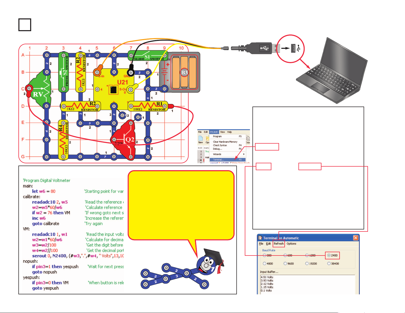
Project B22 Digital Voltmeter
Build the circuit as shown. Turn on the
slide switch (S1). Load program Digital
Voltmeter into the microcontroller (U21)
using the programming instructions in
project B1. Press the F8 key or select
Terminal under the PICAXE menu to open
a terminal window for communication with
the microcontroller, set the baud rate to
2400, and select Refresh.
The microcontroller will measure the
voltage at input 1, which is set using the
adjustable resistor (RV). Set the lever on
RV to any position, then push the press
switch (S2) to measure and display the
voltage. Setting the RV lever to the top
position will measure the voltage from your
batteries (B3).
Optional:
-53-
This circuit uses part of the NPN transistor
(Q2) as a reference, to calibrate the ADC in
the microcontroller for correct voltage
measurements. This self-calibration
eliminates the error that would occur as the
batteries discharge, but your measurements
will still have some error.
The adjustable resistor (RV) sets the voltage
to be measured, which will be between 0V
and the battery voltage.
Page 55

Project B23 Battery Tester (4V or less)
This project is similar to the preceding Digital Voltmeter project, but
tests batteries. Modify the preceding circuit to be as shown here.
Turn on the slide switch (S1). Load program Battery Tester into
the microcontroller (U21) using the programming instructions in
project B1. Press the F8 key to open a Terminal as described in
the Digital Voltmeter project.
To test a battery, hold the battery in the position shown, then push
the press switch (S2) to measure and display the voltage. Hold
the battery with negative (–) terminal resting on the 7-snap wire
and the positive (+) terminal touching the end of the red jumper
wire. If measurement is 0.0V or 0.1V, then you are not making
proper contact with the battery terminals, or have the battery upside
down. For 1.5V batteries, if measurement is 1.0V or less, then the
battery is dead and no longer useful. Batteries up to 4.0V can be
measured.
Part B: This circuit uses the 100W resistor (R1) as a “load”, to make
sure the battery works properly when current is being drawn from
it. Remove R1 from the circuit and re-test some batteries. The
measured voltage may be higher now; the difference will be slight
for batteries that are new or of high quality, and higher for batteries
that are older or of lower quality. You can use this test to compare
different battery brands.
You can also replace R1 with the motor (“+” on right) and fan. This
makes the “load” heavier, and the measured voltage for a battery
will be lower.
Optional:
!
WARNING: Moving parts.
Do not touch the fan or
motor during operation. Do
not lean over the motor.
-54-
A battery make electricity using a
chemical reaction, but has a
limited amount of chemicals and
not all of it can react at the same
time. When a battery cannot
supply as much current as a circuit
needs, the voltage (electrical
pressure) drops.
Engineers refer to this as putting a
load on a battery, because it is the
burden the battery is carrying.
+
–
Page 56

Project B24 Battery Tester (20V or less)
This project is similar to the preceding one, but
adds a buffer so you can measure higher voltage
batteries. Build the circuit as shown, but leave the
ends of the red & black jumper wires unconnected.
Turn on the slide switch (S1).
Load program Battery Tester 20V into the
microcontroller (U21) using the programming
instructions in project B1. Press the F8 key or select
Terminal under the PICAXE menu to open a
terminal window for communication with the
microcontroller, set the baud rate to 4800, and
select Refresh. Voltage measurements will be
displayed in the Terminal.
To test a battery, hold the loose ends of the red &
black jumper wires to the terminals of the battery,
as shown. If measurement is negative then reverse
your connection to the battery terminals. If
measurement is 0.0V or 0.1V, then you are not
making proper contact with the battery terminals.
Optional:
-55-
–
+
This circuit uses resistors to reduce
the voltage measured, so that it will
be within the measurement range
of the ADC in the microcontroller. It
will be a little less accurate than the
Digital Voltmeter project.
Page 57

Project B25 Clap Light
In this circuit, you turn a light on and off by
clapping. Build the circuit as shown. Turn on the
slide switch (S1). Load program Clap Light into
the microcontroller (U21) using the programming
instructions in project B1. After programming,
disconnect the programming cable; the circuit
may not work properly if the cable is still
connected.
When the program starts running, the green LED
(D2) will be on for about 40 seconds and then
turn off. During this time, the program is waiting
for the 470mF capacitor (C5) to charge up. Just
before the green LED goes off, the program
measures the level of room background noise. If
the room is very quiet, then the circuit will be
more sensitive.
Now clapping will control the red LED (D1). Clap
twice or more with a short pause between. The
red LED (D1) should turn on or off. If the red LED
doesn’t change then keep clapping and adjust
the time between claps. Sometimes tapping on
the table may switch the red LED.
If your Clap Light still doesn’t work then turn the
switch off and on to reset and re-measure the
room background noise. Keep the room quiet so
there is less background noise, so the circuit will
be more sensitive.
Optional:
-56-
Sounds into the microphone produce brief electrical
signals, which are measured by the microcontroller.
The microcontroller initially measures the room
background noise as a reference, then looks for
larger electrical signals that could be claps.
Electrically, a clap is a sharp, brief burst of energy.
Disconnect cable
after programming
Page 58

Project B26 Clap Music
This project is similar to the Clap Light, except here you turn on
music by clapping. Build the circuit as shown. Turn on the slide
switch (S1). Load program Clap Music into the microcontroller
(U21) using the programming instructions in project B1. After
programming, disconnect the programming cable; the circuit may
not work properly if the cable is still connected.
When the program starts running, the red LED (D1) will be on,
but wait about 40 seconds until the green LED (D2) turns on.
During this time, the program is waiting for the 470mF capacitor
(C5) to charge up. Just before the green LED turns on, the
program measures the level of room background noise. If the
room is very quiet, then the circuit will be more sensitive.
Now clapping will control music. Clap twice or more with a short
pause between. Music should start. If the music doesn’t start
then keep clapping and adjust the time between claps.
Sometimes tapping on the table may start the music.
If your Clap Music still doesn’t work then turn the switch off and
on to reset and re-measure the room background noise. Keep
the room quiet so there is less background noise, so the circuit
will be more sensitive.
Optional:
-57-
Disconnect cable
after programming
Page 59

Project B27 Test the Microcontroller
This project was created to test the microcontroller (U21) and
all its connections, but is interesting and fun as well. It is
referenced by point 11 of the Advanced Troubleshooting
section on page 8. The programming cable and other Snap
Circuits
®
parts can be tested independently by points 1-10 in
the Advanced Troubleshooting section.
Build the circuit as shown. Turn on the slide switch (S1). Load
the program Test the Microcontroller into the microcontroller
using the programming instructions in project B1. Both LEDs
(D1 & D2) should be on. Push the press switch (S2) to turn off
the red LED. This confirms the microcontroller is working
properly.
Note: If you get a “hardware not found” error while trying to
download a program to the microcontroller: Start the download
and then reset the circuit (switch the circuit off and on). A
running program will be interrupted by a new download when
it executes a command, but some commands (such as long
pause or wait commands) can take too long to complete, so
the download could be ignored. Reseting the microcontroller
just after initiating a download ensures that the microcontroller
will recognize the new download. If you still get an error then
test your programming cable using point 10 of the Advanced
Troubleshooting. If it still doesn’t work then your microcontroller
is damaged.
Optional:
-58-
Page 60

Snap Circuits®XPTMis an introduction to what you can do with
microcontrollers, such as the PICAXE®08M2 IC that you have
been using. This section is intended for users who would like to
develop their own programs for the microcontroller.
Review the
DO’s and DON’Ts of Building Circuits on page 8 before
experimenting on your own.
BASIC Programming:
The programs you are using are written in a language called BASIC.
BASIC (short for Beginner’s All-purpose Symbolic Instruction Code)
is a language of symbolic commands, which will later be translated
into coded instructions that the microcontroller can understand and
execute. The microcontroller you have can process about 1000
BASIC commands a second.
You can download 80-220 lines of code in the microcontroller (the
PICAXE
®
08M2), depending on the commands used. Other
PICAXE®parts available can hold as much as 3200 lines of code.
As programs become complex it is possible the micro-controller will
run out of memory to store the program. Most programs can be
reduced in size by rewriting to use more subroutines. You can check
the program length using ‘Syntax’.
A description of all the microcontroller commands and some basic
programming techniques can be found under the Help menu at
Snap Circuits
®XPTM
.
The PICAXE®Manual (Parts 1, 2, and 3) has more detailed
explanations of the PICAXE
®
commands, and other information
about PICAXE®products, however much of this information is
not applicable to Snap Circuits®XPTMand some is very technical.
The Snap Circuits®XPTMhelp file is customized to your product.
The PICAXE®Interface and
Programming Software
The Snap Circuits®XPTMEditor makes
downloading programs to the
microcontroller easy. It also allows you
to easily change parameters in
programs before downloading.
However, we do not recommend
developing new programs with it,
because more advanced editors are
available with features like simulation
and flowcharting.
The microcontroller you are using has
a special programming interface that
makes it easy to use. This interface,
called PICAXE
®
, was developed by
Revolution Education Ltd.. Revolution
Education’s PICAXE
®
website,
www.rev-ed.co.uk/picaxe, contains the
following:
● More information about PICAXE
®
microcontrollers and software. This
includes information on the larger
PICAXE
®
IC’s that are available, and
where you may purchase them.
● Logicator: Logicator is more
advanced software for programming
PICAXE
®
microcontrollers, including
yours. We recommend this as the
best software for young users who
are creating their own programs for
the microcontroller, due to its ease of
use. Programs are created as
graphical flowcharts, not as typed
BASIC programs. The flowcharts
make creating programs easy
because you select the commands
as symbols from menus, then select
the parameters you need from a list.
Flowcharts make it easy to see how
different parts of a program relate.
With Logicator you can simulate a
program to see how it will work,
before downloading it into the microcontroller. Logicator is available on
the PICAXE®website as a free
download. Further information and a
sample Logicator screen is on the
next page.
●
Programming Editor: The
Programming Editor is the most
advanced software for programming
PICAXE
®
microcontrollers, including
yours. We recommend this as the
best software for advanced users
who are creating their own programs
for the microcontroller, due to its
range of features. Programs are
written in BASIC, but may also be
created as flowcharts (though the
flowcharts here are not as easy to
use as those in Logicator). All
PICAXE
®
features are supported.
Great simulation tools, to help you
test complex programs before
downloading them to the
microcontroller. The Programming
Editor is available on the PICAXE
®
website as a free download. Most of
the programs for Snap Circuits
®XPTM
were created using the Programming
Editor. Further information and a
sample Programming Editor screen
is on page 61.
-59-
PART C - To Go Further
Page 61

Notes on Logicator
● The software may give you a warning about your download
cable not being installed correctly; don’t worry, your cable
style is different but it is compatible and will work.
● We suggest you begin by viewing the Logicator manual,
which can be found under the Help menu.
● When you begin, you will need to select the PIC type and
COM port; these can be found under the Options menu.
Your PIC is the PICAXE08M2. Your COM port is the same
one shown in the XP Editor. See the Logicator manual for
more explanation.
● Logicator programs may be converted to BASIC; BASIC
programs can be used with Logicator but in an abstract
manner.
Sample Logicator Screen
-60-
The flowcharts have symbolic commands. These
are similar to BASIC commands, but are presented
graphically so it is easier to see the program
structure.
Flowcharts can be thought of as road maps for
writing programs, because they give you a better
idea of where you are and where you are going.
Flowcharts make it easier to see how different parts
of a program relate, reducing mistakes.
Flowcharts may seem confusing at first, but actually
they are easy to use. With flowcharts you just select
commands from the menus and enter parameters,
while with BASIC you have to remember commands
and type them in just right.
Page 62

Notes on Programming Editor
●
When you begin, you will need to select the
Mode and COM port. Set the mode to
08M2. See the PICAXE Getting Started
manual for more explanation.
● We suggest you begin by viewing the
PICAXE Getting Started, which can be
found under the Help menu.
● The same BASIC programs may be used
with the Programming Editor and AXEpad
for Snap Circuits
®XPTM
.
Sample Programming Editor Screen - Flowchart mode
Sample Programming Editor Screen
-61-
Page 63

-62-
For a listing of local toy retailers who carry Snap Circuits®visit www.elenco.com or call us toll-free at 800-533-2441. For Snap Circuits
®
upgrade kits, accessories, additional parts, and more information about your parts visit www.snapcircuits.net.
Build over 100 projects
Including:
Snap Circuits®Jr.
Model SC-100
• Flying saucer
• Spin draw
• Sound activated switch
• Alarm circuit
Contains over 30 parts
Including:
• Photoresistor
• Motor
• Music IC
• Space War IC
Build over 300 projects
Including:
Snap Circuits
®
Model SC-300
• AM radio
• Radio announcer
• Lie detector
• Burglar alarm
Contains over 60 parts
Including:
• Two transistors
• Microphone
• Power amplifier IC
• Variable capacitor
Build over 500 projects
Including:
Snap Circuits®Pro
Model SC-500
• Digitally tuned FM radio
• Adjustable light control
• Digital voice recorder
• AC generator
Contains over 75 parts
Including:
• Recording IC
• FM module
• Transformer
• Analog meter
Build over 750 projects
Including:
Snap Circuits®Extreme
Model SC-750
• Strobe light
• Transistor AM radio
• Electromagnetism
• Rechargeable battery
Contains over 80 parts
Including:
• Solar cell
• Electromagnet
• Vibration switch
• Computer interface
Snap Circuits®Green
Model SCG-125
Build over 75 projects
Projects relate to electricity in the home and
magnetism and how it is used.
Snaptricity
®
Model SCBE-75
Contains over 40 parts
Including:
Meter, electromagnet, motor, lamps, switches,
fan, compass, and electrodes.
Alternative Energy Kit
Build over 125 projects and have loads of fun learning
about environmentally-friendly energy and how the
electricity in your home works. Includes full-color manual
with over 100 pages and separate educational manual.
This educational manual will explain all the forms of
environmentally-friendly energy including: geothermal,
hydrogen fuel cells, wind, solar, tidal, hydro, and others.
Contains over 40 parts.
Deluxe Snap Rover
®
Model SCROV-50
Features:
• Disc shooter
• Digital voice recorder
• Music sounds
• Goes forward &
backward
• Headlight
• Red & blue side lights
• Wireless remote control
• Left & right turning
control
Contains over 60 projects
and over 50 parts
Snap Circuits®Light
Model SCL-175
Build over 175 projects
Including:
Contains over 55 parts
Including:
Strobe light, color organ, infrared detector, color
changing LED, fiber optic cable, and more!
• Fiber Fun
• Dancing Lights
• Follow the Music
• Audio Infrared Detector
OTHER SNAP CIRCUITS®PRODUCTS!
Page 64

SCXP-50 XPTMBlock Layout
Important: If any parts are missing or damaged, DO NOT RETURN TO RETAILER.
Call toll-free (800) 533-2441 or e-mail us at: help@elenco.com. Customer Service • 150 Carpenter Ave.
Wheeling, IL 60090 U.S.A.
 Loading...