

Page 1
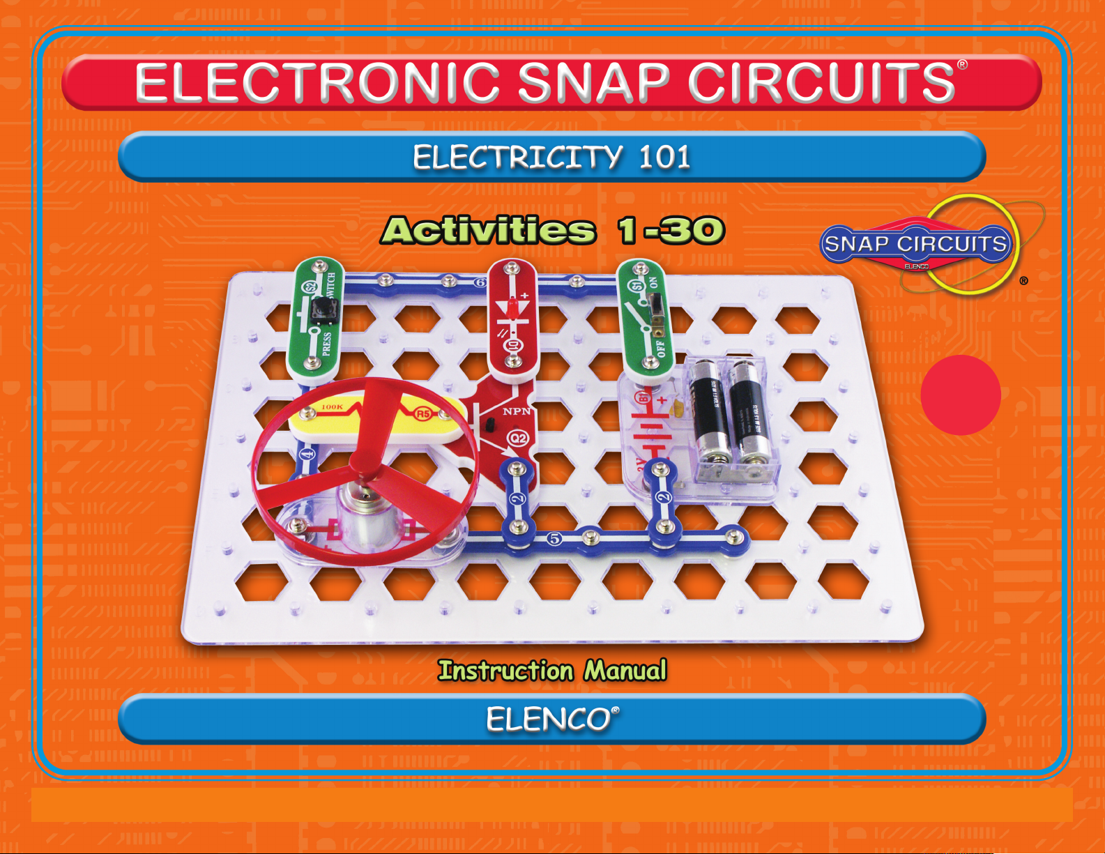
AGES
8 & up
Copyright © 2014 by ELENCO®All rights reserved. No part of this book shall be reproduced by 753043
any means; electronic, photocopying, or otherwise without written permission from the publisher.
Patents 7,144,255, 7,273,377; & other patents pending
Page 2
Table of Contents
Basic Troubleshooting 1
Parts List 2
How to Use It 3
DO’s and DON’Ts of Building Circuits 4
Advanced Troubleshooting 5
WARNING TO ALL PARTS WITH A SYMBOL - Moving parts. Do not touch the motor or fan during operation.
!
Do not lean over the motor. Do not launch the fan at people, animals, or objects. Eye protection is
WARNING: SHOCK HAZARD - Never connect Snap Circuits®to the
electrical outlets in your home in any way!
WARNING: Always check your wiring
before turning on a circuit. Never leave a
circuit unattended while the batteries are
installed. Never connect additional
batteries or any other power sources to
your circuits. Discard any cracked or
broken parts.
Snap Circuits®Electricity 101 is a tool for opening the exciting world of electronics.
Following the Learn by Doing®concept, electronics will be easy to understand by building
circuits as you learn about them. This book emphasizes the practical applications of
electronics, without bogging down in mathematics. This book is as much about science as
about electronics. It will take about 3 hours to complete this book.
Why should you learn about electronics? Electronics plays an important and increasing
role in our everyday lives, and so some basic knowledge of it is good for everyone. Learning
about it teaches how to do scientific investigation, and the activities develop basic skills
needed in today’s world.
!
Adult Supervision: Because children’s
abilities vary so much, even with age
groups, adults should exercise discretion
as to which experiments are suitable and
safe (the instructions should enable
supervising adults to establish the
experiment’s suitability for the child).
Basic Troubleshooting
1. Most circuit problems are due to incorrect assembly, always double-check that your circuit
exactly matches the drawing for it.
Be sure that parts with positive/negative markings are positioned as per the drawing.
2.
3. Be sure that all connections are securely snapped.
4. Try replacing the batteries.
ELENCO®is not responsible for parts damaged due to incorrect wiring.
Note: If you suspect you have damaged parts, you can follow the Advanced Troubleshooting
procedure on page 6 to determine which ones need replacing.
Summary of Parts & Circuit Diagram Symbols
Activity Listings 9
Activities 1 - 30 10 - 37
Vocabulary 38-40
End of Unit Test 41-43
WARNING: CHOKING HAZARD
!
parts. Not for children under 3 years.
Make sure your child reads and follows all
of the relevant instructions and safety
procedures, and keeps them at hand for
reference.
This product is intended for use by adults
and children who have attained sufficient
!
•
Use only 1.5V AA type, alkaline batteries (not incl.).
• Insert batteries with correct polarity.
• Non-rechargeable batteries should not be
recharged. Rechargeable batteries should only be
charged under adult supervision, and should not be
recharged while in the product.
• Do not mix alkaline, standard (carbon-zinc), or
rechargeable (nickel-cadmium) batteries.
• Do not mix old and new batteries.
• Remove batteries when they are used up.
• Do not short circuit the battery terminals.
• Never throw batteries in a fire or attempt to open its
outer casing.
• Batteries are harmful if swallowed, so keep away
from small children.
!
- Small
maturity to read and follow directions and
warnings.
Never modify your parts, as doing so may
disable important safety features in them,
and could put your child at risk of injury.
Batteries:
6-8
Conforms to all applicable US
government requirements.
Meets academic standards
for elementary science.
-1-
Page 3
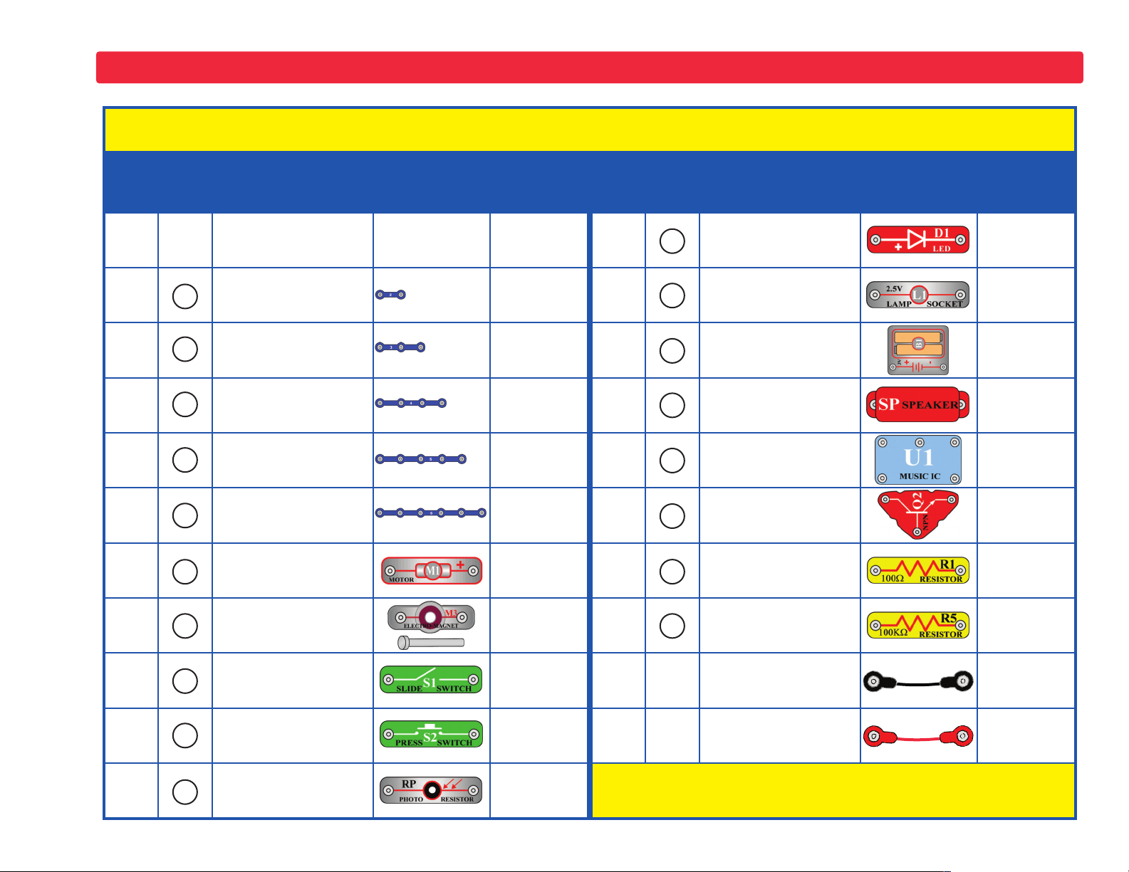
Parts List (Colors and styles may vary) Symbols and Numbers
Important: If any parts are missing or damaged, DO NOT RETURN TO RETAILER. Call toll-free (800) 533-2441 or e-mail us at:
help@elenco.com. Customer Service • 150 Carpenter Ave. • Wheeling, IL 60090 U.S.A.
Qty. ID Name Symbol Part # Qty. ID Name Symbol Part #
r 1
r 2
r 2
r 1
r 1
r 1
r 1
r 1
r 1
r 1
2
3
4
5
6
M1
M3
Base Grid
(11.0” x 7.7”)
2-Snap Wire 6SC02
3-Snap Wire 6SC03
4-Snap Wire 6SC04
5-Snap Wire 6SC05
6-Snap Wire 6SC06
Motor
Fan Blade
Electromagnet
Iron Core Rod
6SCBG
6SCM1
6SCM1F
6SCM3
6SCM3B
r 1
r 1
r 1
r 1
r 1
r 1
r 1
r 1
D1
L1
B1
SP
U1
Q2
R1
R5
Red Light Emitting
Diode (LED)
2.5V Lamp
Battery Holder 2 1.5V type AA (not included)
Speaker 6SCSP
Music
Integrated Circuit
NPN Transistor 6SCQ2
100Ω Resistor 6SCR1
100kΩ Resistor 6SCR5
uses
(STANDING)
6SCD1
6SCL1
6SCB1
6SCU1
r 1
r 1
r 1
S1
S2
RP
Slide Switch 6SCS1
Press Switch 6SCS2
Photoresistor 6SCRP
r 1
r 1
Jumper Wire (Black) 6SCJ1
Jumper Wire (Red) 6SCJ2
You may order additional / replacement parts at our
website: www.snapcircuits.net
-2-
Page 4
How to Use It
®
Snap Circuits
simple to build and understand.
The Snap Circuits®kit uses building blocks with snaps to
build the different electrical and electronic circuits in the
projects. Each block has a function: there are switch blocks,
lamp blocks, battery blocks, different length wire blocks, etc.
These blocks are in different colors and have numbers on
them so that you can easily identify them. The circuit you will
build is shown in color and with numbers, identifying the
blocks that you will use and snap together to form a circuit.
For Example:
This is the switch block which is green and has the marking
on it as shown in the drawings.
S1
Please note that the drawing doesn’t reflect the real switch
block exactly (it is missing the ON and OFF markings), but
gives you the general idea of which part is being used in the
circuit.
Electricity 101 has 30 projects. They are
To build each circuit, you have a power source block number
B1
that needs two (2) “AA” batteries (not included with the
Snap Circuits®kit).
A large clear plastic base grid is included with this kit to help
keep the circuit blocks properly spaced. You will see evenly
spaced posts that the different blocks snap into. You do not
need this base to build your circuits, but it does help in
keeping your circuit together neatly. The base has rows
labeled A-G and columns labeled 1-10.
Next to each part in every circuit drawing is a small number
in black. This tells you which level the component is placed
at. Place all parts on level 1 first, then all of the parts on
level 2, then all of the parts on level 3, etc.
Place the fan on the motor whenever that part is used,
unless the project you are building says not to use it.
Some circuits use the jumper wires to make unusual
connections. Just clip them to the metal snaps or as
indicated.
M1
This is a wire block which is blue and comes in different wire
lengths.
This one has the number , , , , or on it
depending on the length of the wire connection required.
-3-
2 3 4 5 6
Note: While building the projects, be careful not to
accidentally make a direct connection across the battery
holder (a “short circuit”), as this may damage and/or quickly
drain the batteries.
Page 5
DO’s and DON’Ts of Building Circuits
After building the circuits given in this booklet, you may wish to
experiment on your own. Use the projects in this booklet as a guide, as
many important design concepts are introduced throughout them. Every
circuit will include a power source (the batteries), a resistance (which
might be a resistor, lamp, motor, integrated circuit, etc.), and wiring paths
between them and back.You must be careful not to create “short circuits”
(very low-resistance paths across the batteries, see examples below)
as this will damage components and/or quickly drain your batteries. Only
connect the IC using configuration given in the projects, incorrectly doing
so may damage it. ELENCO®is not responsible for parts damaged
due to incorrect wiring.
Here are some important guidelines:
ALWAYS use eye protection when experimenting on your own.
ALWAYS include at least one component that will limit the current
through a circuit, such as the speaker, lamp, electromagnet,
music IC (which must be connected properly), motor,
photoresistor, or resistor.
ALWAYS use the LED and switches in conjunction with other
components that will limit the current through them. Failure to
do so will create a short circuit and/or damage those parts.
ALWAYS disconnect your batteries immediately and check your wiring
if something appears to be getting hot.
ALWAYS check your wiring before turning on a circuit.
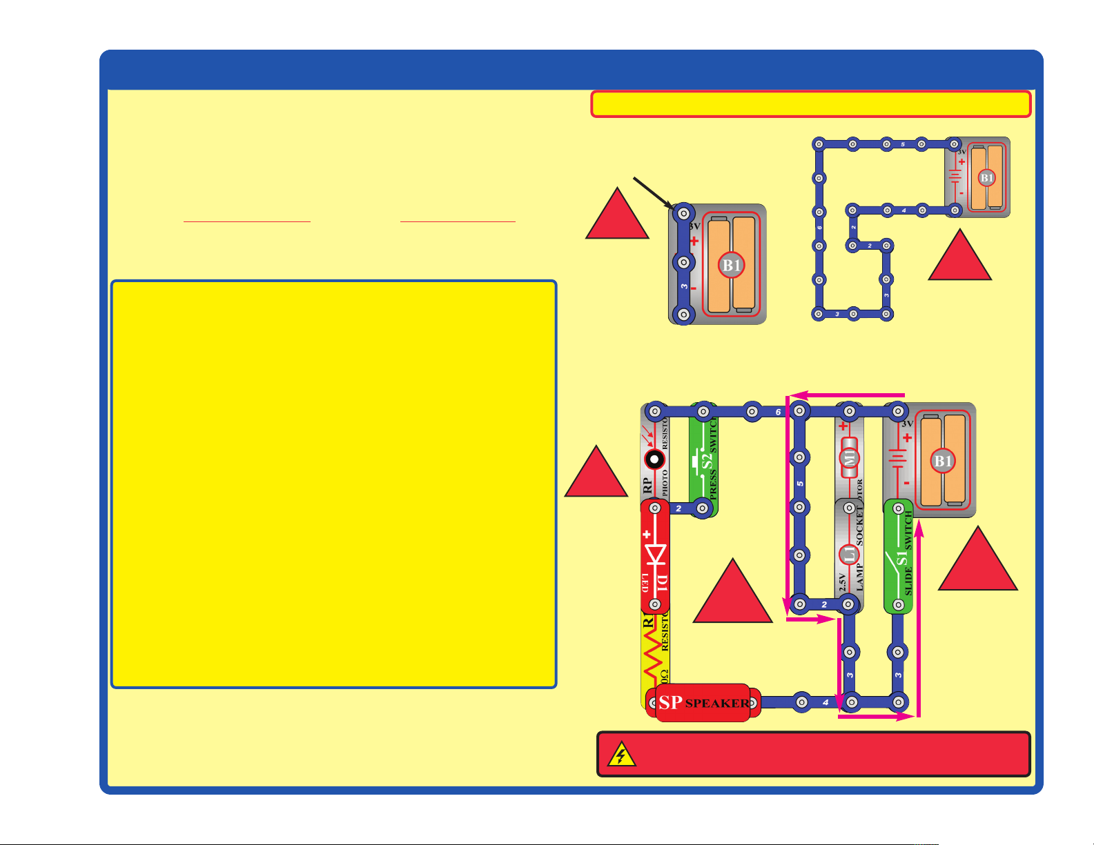
Examples of SHORT CIRCUITS - NEVER DO THESE!!!
Placing a 3-snap wire directly
across the batteries is a
SHORT CIRCUIT.
This is also a
SHORT CIRCUIT.
!
NEVER
DO!
When the slide switch (S1) is turned on, this large circuit has a SHORT
CIRCUIT path (as shown by the arrows). The short circuit prevents any
other portions of the circuit from ever working.
!
NEVER
DO!
!
NEVER
DO!
ALWAYS connect the music IC using configurations given in the
projects or as per the connection descriptions for it.
NEVER connect to an electrical outlet in your home in any way.
NEVER leave a circuit unattended when it is turned on.
NEVER touch the motor when it is spinning at high speed.
For all of the projects given in this book, the parts may be arranged in
different ways without changing the circuit. For example, the order of
parts connected in series or in parallel does not matter — what matters
is how combinations of these sub-circuits are arranged together.
!
!
NEVER
DO!
(STANDING)
WARNING: SHOCK HAZARD - Never connect your Snap
Circuits®set to the electrical outlets in your home in any way!
NEVER
DO!
-4-
Page 6
Advanced Troubleshooting
(Adult supervision recommended)
ELENCO®is not responsible for parts damaged due to incorrect
wiring.
If you suspect you have damaged parts, you can follow
this procedure to systematically determine which ones
need replacing:
1. 2.5V lamp (L1), motor (M1), speaker (SP), and battery holder
(B1): Place batteries in holder. Place the 2.5V lamp directly
across the battery holder, it should light. Do the same with the
motor (motor + to battery +), it should spin to the right at high
speed. “Tap” the speaker across the batttery holder contacts,
you should hear static as it touches. If none work then replace
your batteries and repeat, if still bad then the battery holder is
damaged.
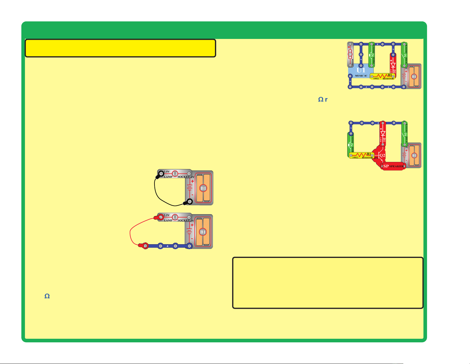
2. Jumper wires: Use this minicircuit to test each jumper
wire, the lamp should light.
6.
Music IC (U1): Build the circuit
shown here. Turn it on and the LED
(D1) flickers for a while and stops, it
should resume if you spin the motor
(M1) or push the press switch (S2).
7.
NPN transistor (Q2), 100kΩresistor (R5), and Photoresistor
(RP): Build the mini-circuit shown here. The LED (D2) should
only be on if the press switch (S2) is pressed; if otherwise then
the NPN is damaged.
• Replace the 100Ω resistor (R1)
with the 100kΩ resistor (R5). The
LED should light when the press
switch is pressed; otherwise the
100kΩ resistor is damaged.
• Replace the 100kΩ resistor with the photoresistor. The LED
should light when the press switch is pressed and there is
light on the photoresistor; otherwise the photoresistor is
damaged.
3.
Snap wires: Use this mini-
circuit to test each of the snap
wires, one at a time. The lamp
should light.
4. Slide switch (S1) and Press switch (S2): Build activity 1, if
the lamp (L1) doesn’t light then the slide switch is bad. Replace
the slide switch with the press switch to test it.
100Ωresistor (R1) and LED (D1): Build activity 6 except
5.
initially use the speaker (SP) in place of the LED, you will hear
static if the resistor is good. Then replace the speaker with the
LED and see that it lights.
-5-
8.
Electromagnet (M3): Use the circuit for activity 18, and place
the iron core rod in the electromagnet. When you push the press
switch (S2), a metal paperclip or small iron nail should be
attracted to the iron core rod; if no attraction then the
electromagnet is damaged.
ELENCO
®
150 Carpenter Avenue
Wheeling, IL 60090 U.S.A.
Phone: (847) 541-3800 • Fax: (847) 520-0085
e-mail: help@elenco.com • Website: www.elenco.com
You may order additional / replacement parts at:
www.snapcircuits.net
Page 7
Summary of Parts & Circuit Diagram Symbols
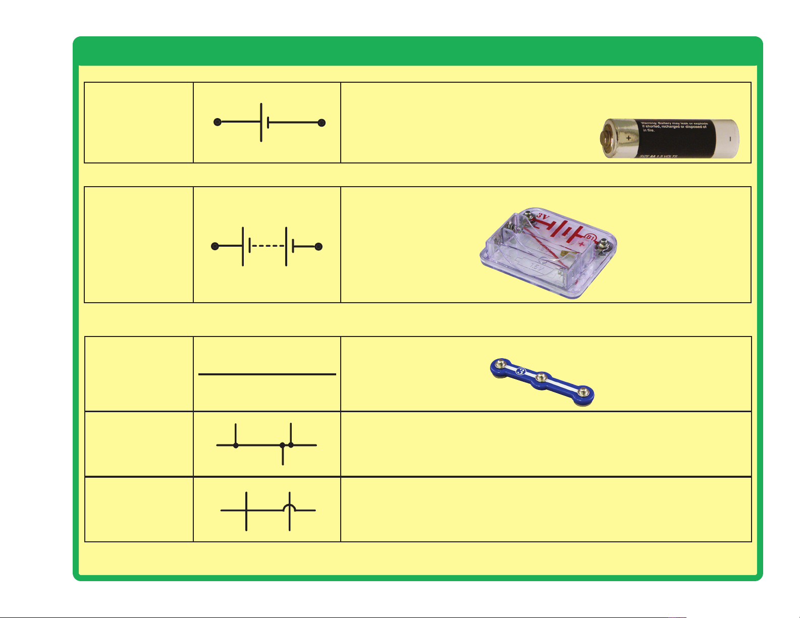
Produces electrical energy using a chemical reaction. The larger terminal
(on the left) is positive (+). A single cell is often called a battery, but strictly
Dry Cell
2 Cell Battery (B1)
a battery is two or more cells joined together.
Batteries supply electrical energy. A battery is more than one cell.
Wire
(2, 3, 4, 5, & 6 snap
wires, red and
black jumper wires)
Wires joined
Wires not joined
Used to pass current very easily from one part of a circuit to another. A 3snap wire is shown here.
A ‘blob’ should be drawn where wires are connected (joined), but it is
sometimes omitted. Wires connected at ‘crossroads’ should be staggered
slightly to form two T-junctions, as shown on the right.
In complex diagrams it is often necessary to draw wires crossing even
though they are not connected. Often the ‘bridge’ symbol shown on the right
is used because the simple crossing on the left may be misread as a join
where you have forgotten to add a ‘blob’!
-6-
Page 8
Summary of Parts & Circuit Diagram Symbols
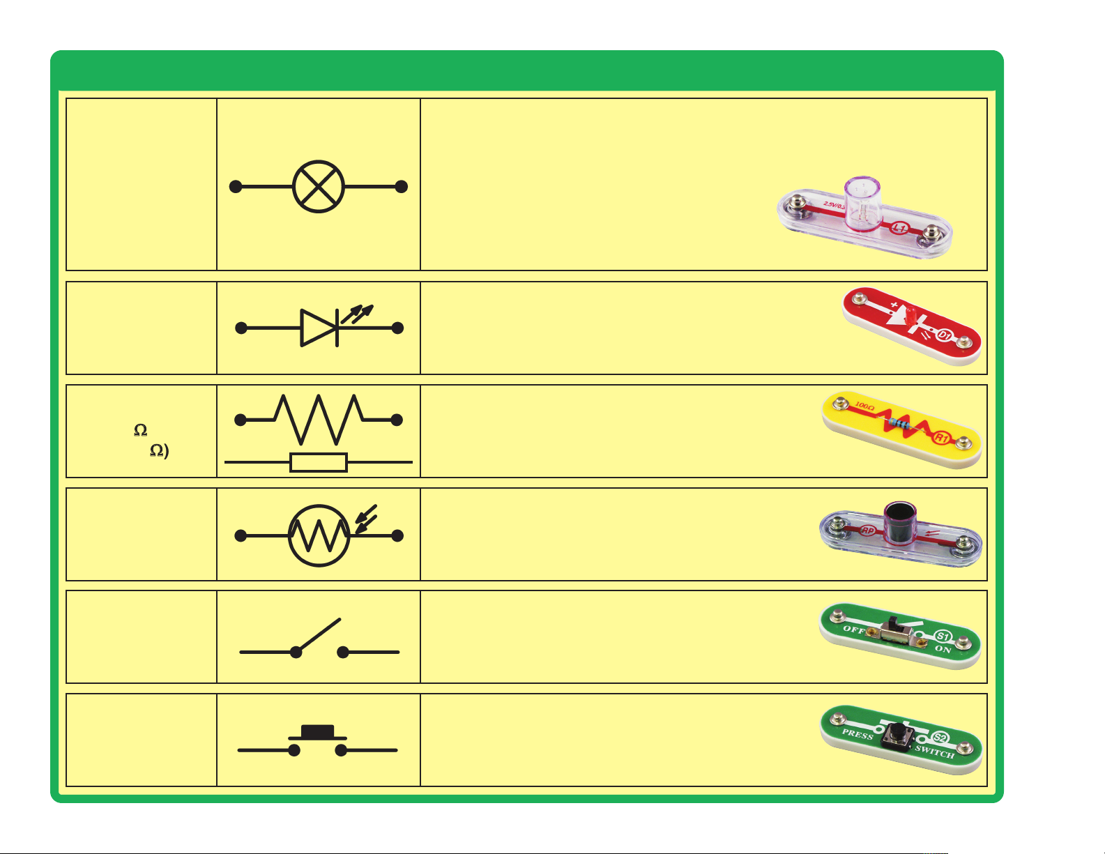
A transducer that converts electrical energy to light. It contains a special wire
that glows bright when a large electric current passes through it. The upper
symbol is used for a lamp providing illumination, for example a car headlamp
Lamp (L1)
or flashlight bulb.
LED (D1)
Light Emitting
Diode
Resistor
(R1 100Ωand R5
100kΩ)
Photoresistor
(RP)
On-Off Switch
(S1)
A transducer that converts electrical energy to light.
A resistor restricts the flow of current through a
circuit.
A resistor whose value changes as light shines on it.
A mechanical switch that allows current to flow only
when it is in the closed (on) position.
Press Switch
(push-to-connect
S2)
-7-
A push switch allows current to flow only when the
button is pressed.
Page 9
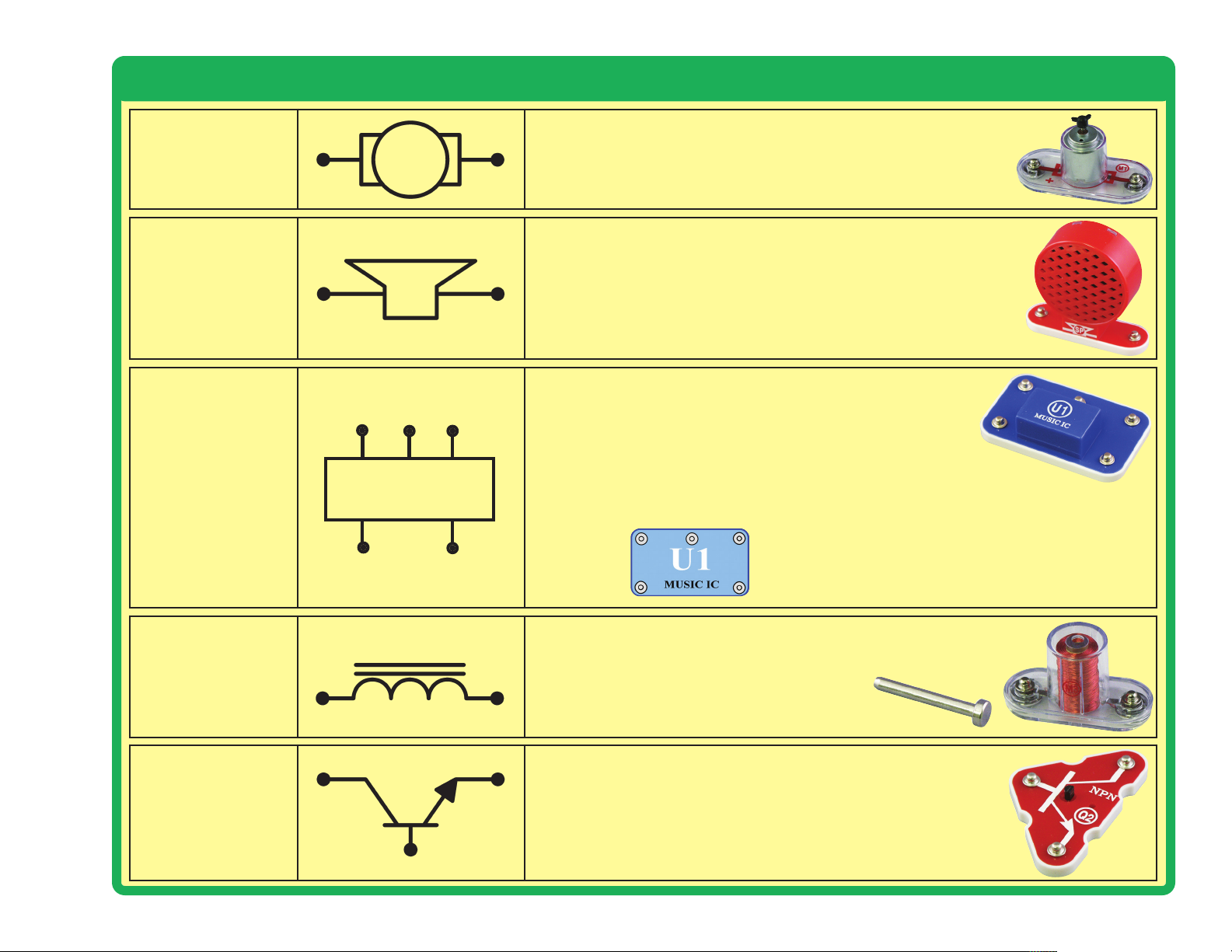
Summary of Parts & Circuit Diagram Symbols
A transducer that converts electrical energy to kinetic energy
Motor (M1)
Speaker (SP)
Music
Integrated Circuit
(U1)
Music IC
(motion).
A transducer that converts electrical energy to sound. An
electrical signal creates mechanical vibrations, which create
variations in air pressure, which travel across the room to
your ears.
A module that converts electrical energy to Music. It
contains a specialized sound-generation circuit with
resistors, capacitors, and transistors. The descriptions
for the music IC module is given here for those
interested, see the projects for connection examples:
Music IC:
(+)
TRG
(–)
(+) - power from batteries
(–) - power return to batteries
HLD
OUT - output connection
HLD - hold control input
TRG - trigger control input
Music for ~20 sec on power-up, then hold HLD to (+) power
OUT
or touch TRG to (+) power to resume music.
Electromagnet
(M3)
with Iron Core
Rod
NPN Transistor
(Q2)
A coil of wire, which acts like a magnet when an electric current
flows through it. Placing an iron bar inside increases the
magnetic effects.
A device that switches or amplifies electrical current.
-8-
Page 10

Activities Listing
Activity # Description Page #
1 Electric Light and Switch 10
2 Motor and Switch 12
3 Lamp and Fan in Series 13
4 Lamp and Fan in Parallel 14
5
6 Light Emitting Diode 16
7 One Direction for the LED 17
8 Conduction Detector 18
9 Morse Code 19
10 Flying Saucer 20
11 Decreasing Lift 20
12 Two-Speed Fan 21
13 Musical Doorbell 22
14 Musical Alarm 23
15 Happy Birthday with Light 24
16 Spinning Rings 25
17 Strobe the House Lights 25
18 The Electromagnet 26
19 This OR That OR Both 27
20 This AND That 28
21 Music AND Gate 29
22 Neither This NOR That 30
23 NOT This AND That 30
24 Reflection Detector 31
25 Math Game 32
26 LED Night Light 33
27 Motor Running LED 34
28 Light Activator 35
29 Sounds, Light, and Motion 36
30 Simple Water Alarm 37
Lamp, Speaker, and Fan in Parallel
15
Objectives: As a result of completion of activities 1 - 30 in this kit, students will:
• Understand basic information about electricity as a form of energy
• Control the flow of electricity through a number of circuits and devices
• Identify the path of electricity through a circuit
• Identify the parts of a circuit
• Repair a non-functioning circuit
• Transform electrical energy into light, sound, and motion
• Identify series and parallel circuits
• Determine if materials are conductors of electricity or insulators
• Observe the effect of resistance on the brightness of a bulb or LED
• Study the motion of a motor
• Produce and study sound from a speaker
• Draw and label circuit diagrams
• Build a Morse Code sender (telegraph using light instead of sound)
• Send and receive messages in Morse code, and decode messages received
• Observe the effect of fluorescent light on a spinning disc
• Observe the effect of electricity on a temporary magnet (electromagnet)
• Use a transistor to switch devices on or off
• Make a circuit that detects the presence of water
• Have a better understanding of the scientific method of investigation
-9-
Page 11
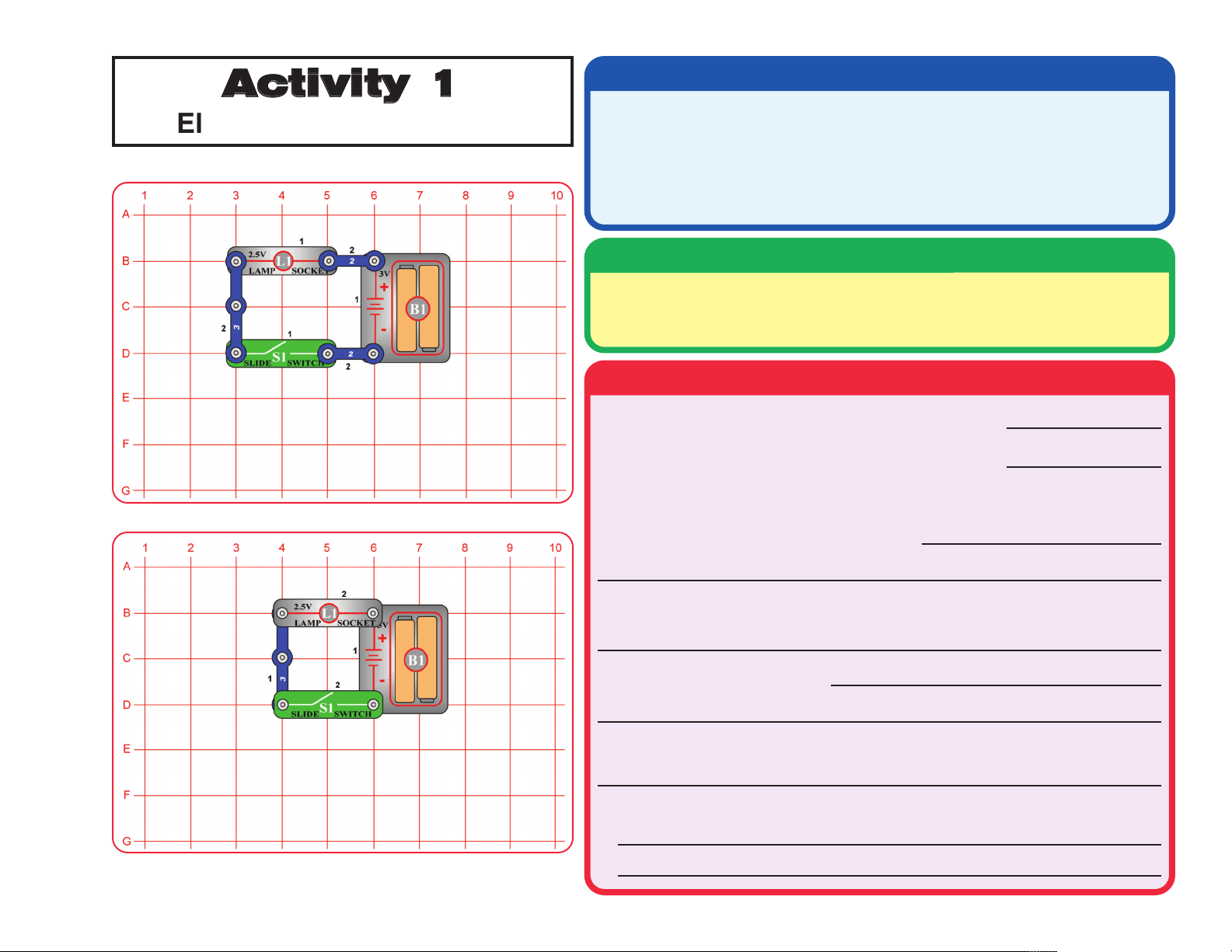
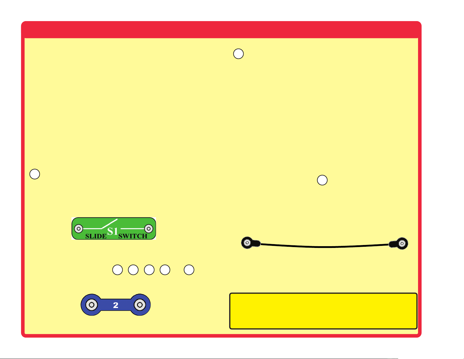
Activity 1
Electric Light and Switch
Materials List
Quantity Description
2 2-Snap Wires
1 3-Snap Wire
1 Battery Holder (B1) with 2 AA batteries (not included)
1 Lamp (L1)
1 Slide Switch (S1)
Assembly
Build the circuit shown on the left by placing the parts with a black 1 next to
them on the board first. Then add the parts with a 2. Install two AA type
batteries (not included) in the holder (B1).
Operation
What happens when you close the switch (turn it on)?
What happens when you open the switch (turn it off)?
Now build this circuit with some of the same parts (lower circuit drawing).
What do the two circuits have in common?
How can you tell when electricity is flowing through the circuit?
Explain how the switch works.
What could you do to open and close this circuit without a switch?
Give two examples of switches used in everyday life.
1.
2.
-10-
Page 12
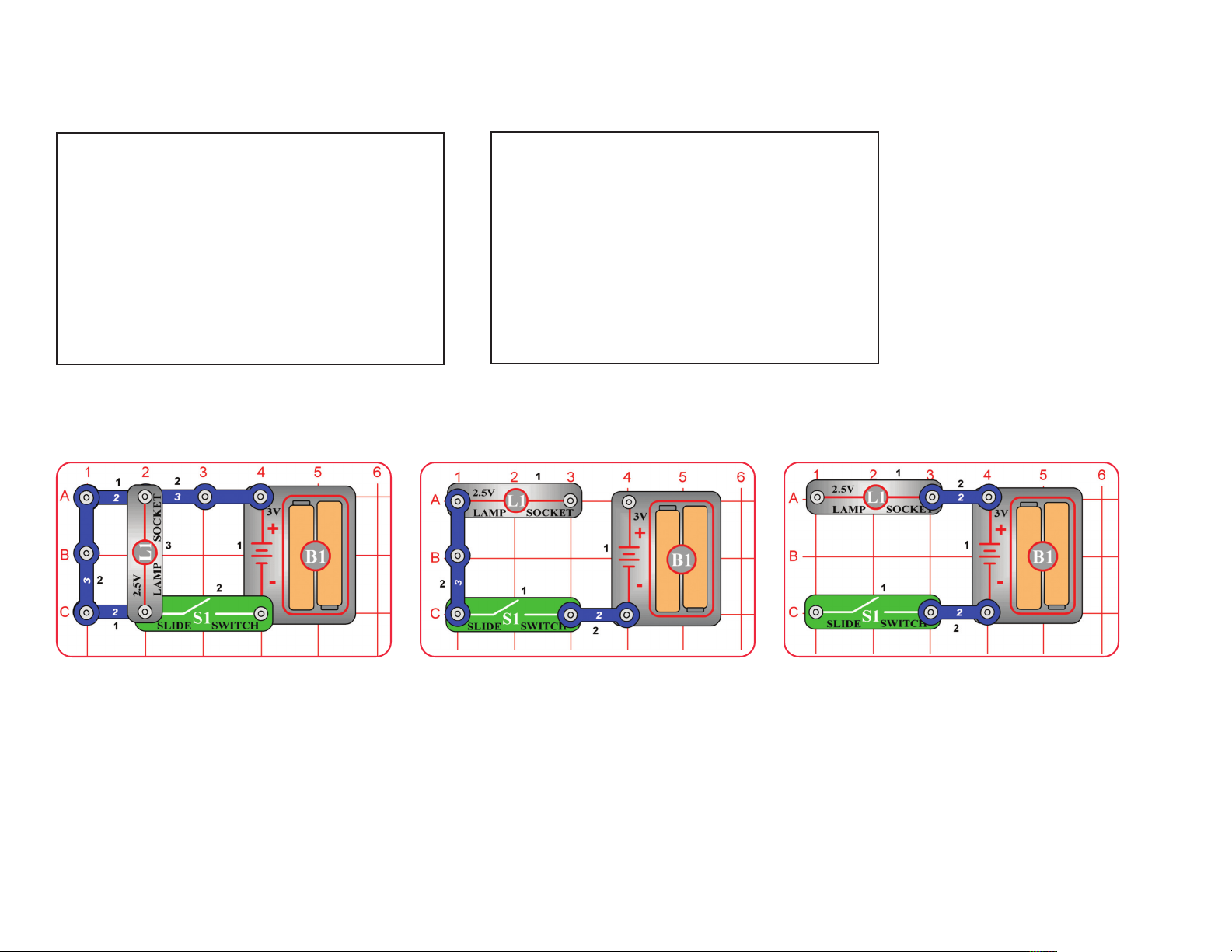
Use the circuit diagram symbols to draw the two circuits you have made on the previous page.
Diagram 1
Tell why these three circuits will not light the lamp, then explain a way to fix the circuits.
A. B. C.
Diagram 2
Circuit A will not light the bulb because
_______________________________
Repair by: _______________________
_______________________________
-11-
Circuit B will not light the bulb because
_______________________________
Repair by: _______________________
_______________________________
Circuit C will not light the bulb because
_______________________________
Repair by: _______________________
_______________________________
Page 13
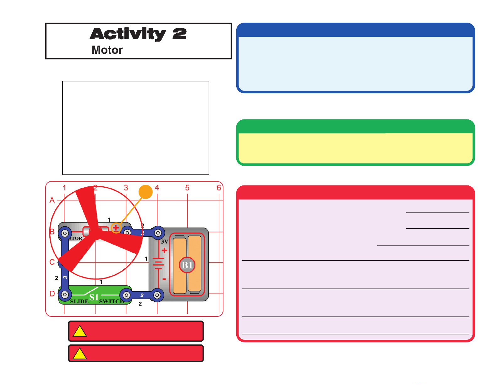
Activity 2
Motor and Switch
Use the circuit diagram symbols to draw the circuit shown below.
Circuit Diagram
Materials List
Quantity Description
2 2-Snap Wires
1 3-Snap Wire
1 Battery Holder (B1)
1 Motor (M1) and Fan Blade
1 Slide Switch (S1)
Assembly
Build the circuit pictured on the left by placing all parts with a black 1 next
to them on the board first. Then assemble the parts with a black 2. Place
the motor (M1) with the “+” side as shown.
+
WARNING: Moving parts. Do not touch
!
the fan or motor during operation.
WARNING: Do not lean over the motor.
!
Operation
What happens when you close the switch (turn it on)?
What happens when you open the switch (turn it off)?
What is the electrical energy changed into?
How is this circuit similar to the lamp circuit in Activity 1?
Think of several examples of tools or toys powered by a motor.
-12-
Page 14
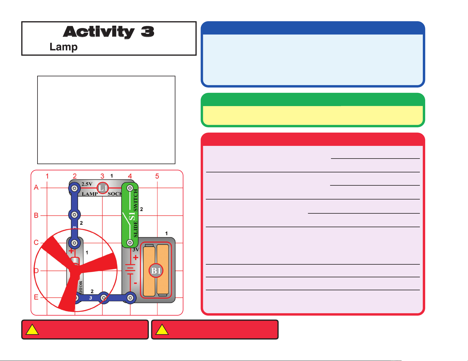
Activity 3
Lamp and Fan in Series
Use the circuit diagram symbols to draw the circuit shown below.
Circuit Diagram
Materials List
Quantity Description
2 3-Snap Wires
1 Battery Holder (B1)
1 Lamp (L1)
1 Motor (M1) and Fan Blade
1 Slide Switch (S1)
Assembly
Build the circuit pictured on the left. Place all the parts with the black 1 next
to them on the board first, then the parts with the black 2.
Operation
What happens when you close the switch?
What happens when you open the switch?
-13-
WARNING: Moving parts. Do not touch
!
the fan or motor during operation.
Remove the lamp. What happens?
Put the lamp back in. Open the switch. Take the fan off the motor. Close the
switch. Describe What happens.
The circuits in Activity 1, 2, and 3 were series circuits. In a series circuit all
of the parts are placed on the board one after the other.
WARNING: Do not lean over the motor.
!
Page 15
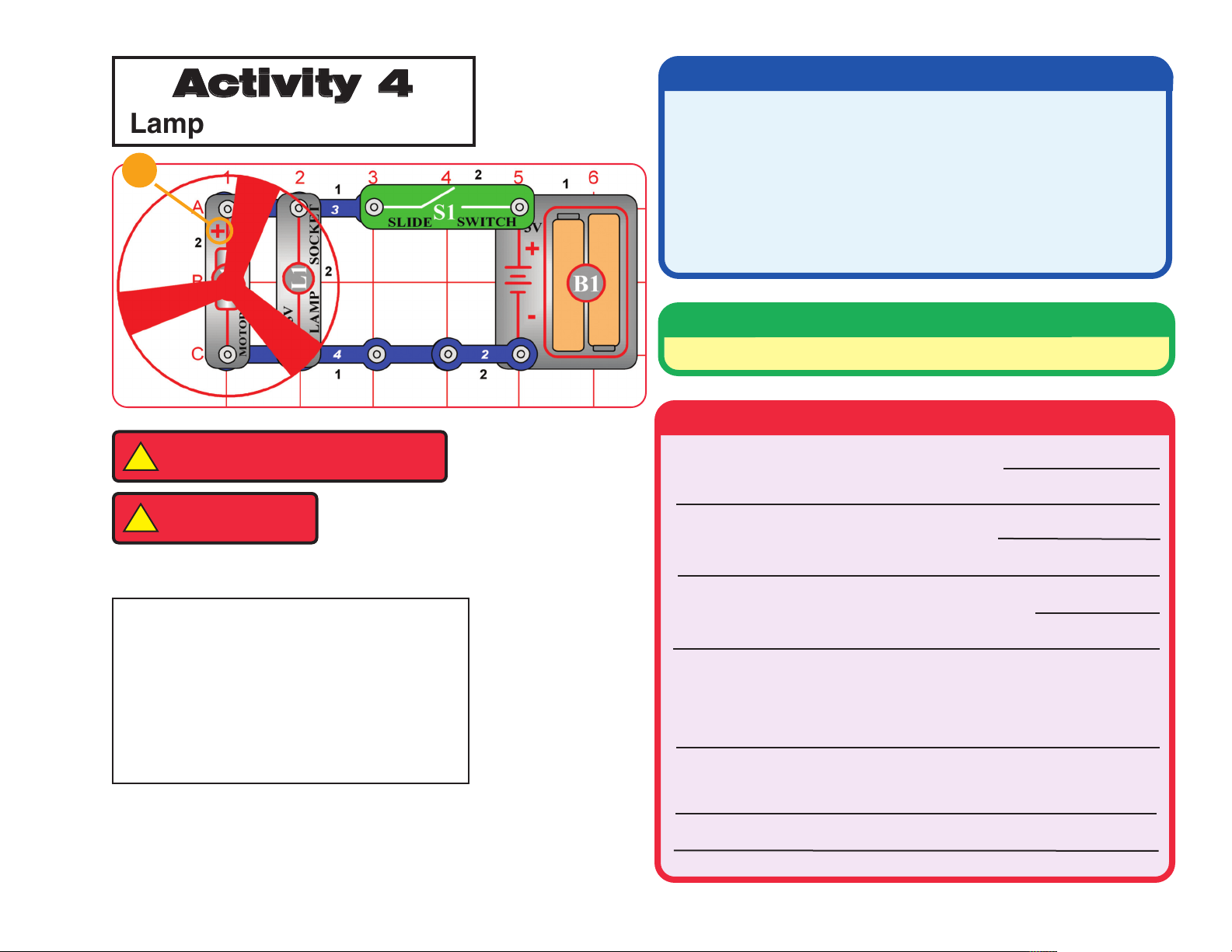
Activity 4
Lamp and Fan in Parallel
+
WARNING: Moving parts. Do not touch
!
the fan or motor during operation.
WARNING: Do not
!
lean over the motor.
Materials List
Quantity Description
1 2-Snap Wire
1 3-Snap Wire
1 4-Snap Wire
1 Battery Holder (B1)
1 Lamp (L1)
1 Motor (M1) and Fan Blade
1 Slide Switch (S1)
Assembly
Build the circuit shown.
Operation
What happens when you close the switch?
What happens when you open the switch?
Use the circuit diagram symbols to draw the circuit:
Remove the lamp. What happens to the motor?
Put the lamp back in. Open the switch. Remove the fan blade
from the motor. Close the switch. What happens to the lamp?
How is a parallel circuit different from a series circuit?
-14-
Page 16

Activity 5
Lamp, Speaker, and Fan in Parallel
Materials List
1 2-Snap wire
1 4-snap wire
1 5-snap wire
1 Battery holder (B1)
1 Press switch (S2)
1 Lamp (L1)
1 Motor (M1) & Fan Blade
1 Speaker (SP)
WARNING: Moving parts. Do not touch
!
the fan or motor during operation.
+
Build the circuit shown on
the left.
(STANDING)
WARNING: Do not
!
lean over the motor.
What happens when you press the switch S2? _______________________________________________________________
Circle the number of paths that exist for the electric current to follow? 1 2 3 4 5 6
Put the fan on the motor when the motor stops spinning. Press the switch. What changes do you notice?
______________________________________________________________________________________________________
What is the purpose of the speaker in the circuit? ______________________________________________________________
Remove the speaker from the circuit. What changes do you notice? _____________________________________________
Remove the lamp. Press the switch. What effect does this have on the motor? ____________________________________
Don't leave the circuit on too long or it will drain the batteries.
Do you think the lights in your home are wired in series or parallel? ______________________________________________
Use the circuit diagram symbols to draw the circuit here.
-15-
Page 17

Activity 6
Build the circuit pictured on the left.
Light Emitting Diode
Materials List
1 Battery Holder (B1)
1 LED (Light Emitting Diode, D1)
1 100Ω Resistor (R1)
1 Slide Switch (S1)
Draw the circuit using the circuit diagram symbols.
Is this a series or parallel circuit? How do you know? _________________________________________________________
______________________________________________________________________________________________________
What happens when you close the switch? __________________________________________________________________
How is this circuit like the circuit in Activity 1? How is it different? ________________________________________________
______________________________________________________________________________________________________
What is the function of the resistor? ________________________________________________________________________
List several devices you have seen that use LED's in them. _____________________________________________________
Why are LED's used instead of a incandescent light bulbs in these devices? _______________________________________
______________________________________________________________________________________________________
-16-
Page 18

Activity 7
One Direction for the LED
Rebuild the circuit used in Activity 6, but put the LED facing in the
opposite direction as shown here.
What happens when you close the switch?
______________________________________________________
What path is the electric current following?
_______________________________________________________
What effect did turning the LED around have on the flow of electric current? _______________________________________
______________________________________________________________________________________________________
LED’s, like batteries, are marked with a polarity or “+” symbol. This side of the LED must always connect to the circuit parts that go
to the “+” side of the battery to make the LED glow.
-17-
Page 19

Activity 8
Conduction Detector
working properly, place a paper
clip across the opening between
the two 2 snap wires as shown
To make sure the circuit is
Materials List
2 2-Snap Wires
1 Battery Holder (B1)
1 LED (D1)
1 100 Ohm Resistor (R1)
1 Red Jumper Wire
1 Paper clip (uncoated)
here. The LED should light up.
When you place the paper clip
across the terminals as shown,
current flows from the batteries
through the resistor, then the
LED, then back to the batteries.
The paper clip completes the
circuit.
Build the circuit as shown.
Listed below are items that you will place across the terminals one at a time to determine if they are conductors (allow electricity
to flow) or insulators (prevents the flow of electricity). Use the jumper wire shown to bridge the gap when testing small items
such as a penny. First predict which materials are conductors or insulators by filling in the blue column in the table below.
Material Prediction Test Result
Clean steel nail
Rusty nail
Piece of chalk
Rubber eraser
Plastic straw
Brass paper fasteners
Copper penny
Aluminum foil strip
Rubber band
Material Prediction Test Result
Key
Cardboard strip
Wooden craft stick
Plastic ruler
Metal paperclip
Plastic coated paperclip
String
Pencil lead from a
mechanical pencil
Test each item and write the result (conductor or insulator) in the green column.
What do all conductors have in common? ___________________________________________________________________
List 2 examples of uses for conductors. ___________________________________________________________________
Which materials are good insulators? ___________________________________________________________________
List 2 examples of insulators used in everyday life. _____________________________________________________________
-18-
Page 20

Activity 9
Morse Code:
Morse Code
Materials List
1 3-Snap Wire
1 Battery Holder (B1)
1 Lamp (L1)
1 Press Switch (S2)
Build the circuit as shown.
You can send a message to your partner using Morse code shown in the box above. At first you should only use the letters from
a to z and the numbers. Morse code is a series of dots and dashes representing the letters of the alphabet. A telegraph sends
messages with sound signals. Your sender uses light instead. If you only hold down the press switch for a short time, you get a
"dot". If you hold the switch down for a longer time you get a "dash".
Using the code, write a sentence to send to your partner. Remember to pause between words. Since your partner is new to
decoding Morse code, try to send your message slowly so your partner has time to write it down. After your partner decodes
your message, your partner will write a message to send to you to decode.
How does a telegraph work? _____________________________________________________________________________
How is your telegraph similar to an actual telegraph? __________________________________________________________
How is it different? _____________________________________________________________________________________
Why were telegraphs important in the past? __________________________________________________________________
Why are telegraphs less important today? ___________________________________________________________________
Name two devices used for communication over great distances. ________________________________________________
-19-
Page 21

Activity 10
Flying Saucer
+
Note that the polarity of the motor is
reversed. The positive terminal of the
battery is connected to the negative
terminal of the motor.
Materials List
2 2-Snap Wires
1 3-Snap Wire
1 Battery Holder (B1)
1 Motor (M1) and Fan Blade
1 Press Switch (S2)
Build the circuit as shown.
Why do you think this happened? _________________________________________________________________________
Push the press switch. Allow the motor
to run until it reaches maximum speed.
Release the press switch to turn off the
current.
What happens? ___________________
________________________________
Activity 11
Decreasing Lift
Slide the switch (S1) to on. Compare this
Materials List
2 2-Snap Wires
1 Battery Holder (B1)
1 Lamp (L1)
1 Motor (M1) and Fan Blade
1 Slide Switch (S1)
circuit to activity 10.
Build the circuit as shown.
What does the lamp do to the motor in the circuit? ____________________________________________________________
When the motor has reached maximum speed, slide the switch off. What happens? ________________________________
______________________________________________________________________________________________________
Is this a series circuit or parallel circuit? ____________________________________________________________________
-20-
Page 22

Activity 12
+
Two-Speed Fan
Build the circuit shown
on the left.
Materials List
2 3-Snap Wires
1 Battery Holder (B1)
1 Lamp (L1)
1 Motor (M1) and Fan Blade
1 Slide Switch (S1)
1 Press Switch (S2)
What is the path of the current through this circuit when only the slide switch is closed? ______________________________
______________________________________________________________________________________________________
What happens when you close the press switch? _____________________________________________________________
______________________________________________________________________________________________________
Is this a series or parallel circuit? __________________________________________________________________________
What is the purpose of the lamp in this circuit? _______________________________________________________________
______________________________________________________________________________________________________
If you have a multiple speed fan at home, how can you increase or decrease the speed? _____________________________
______________________________________________________________________________________________________
-21-
Page 23

Activity 13
Musical Doorbell
Materials List
2 2-Snap Wires
2 3-Snap Wire
1 4-Snap Wire
1 6-Snap Wire
1 Battery Holder (B1)
1 100 Ohm Resistor (R1)
1 Slide Switch (S1)
1 Press Switch (S2)
1 Speaker (SP)
1 Music Integrated Circuit (U1)
Build the circuit as shown.
(STANDING)
Use the circuit diagram symbols to draw the circuit here.
When you close the slide switch, what happens? _____________________________________________________________
To simulate a doorbell, push the button on the press switch.
Do you need to hold the button down to keep the music playing? ___________________________
What kinds of toys do you think could have integrated sound circuits? _____________________________________________
-22-
Page 24

Activity 14
Musical Alarm
Materials List
2 2-Snap Wires
1 3-Snap Wire
1 4-Snap Wire
1 6-Snap Wire
1 Battery Holder (B1)
1 Slide Switch (S1)
1 Press Switch (S2)
1 Speaker (SP)
1 Music Integrated Circuit (U1)
Build the circuit as shown.
When you close the slide switch, the music integrated circuit should play one song and then stop.
(STANDING)
Is this louder or softer than the music in activity 13? ____________ Why? _________________________________________
How are the circuits in activity 13 and 14 different? ___________________________________________________________
______________________________________________________________________________________________________
What happens when you hold the press switch down? _________________________________________________________
What happens when you release the press switch? ___________________________________________________________
What can you do to keep the song playing? __________________________________________________________________
-23-
Page 25

Activity 15
Happy Birthday with Light
Materials List
2 2-Snap Wires
2 3-Snap Wires
1 4-Snap Wire
1 5-Snap Wire
1 6-Snap Wire
1 Battery Holder (B1)
1 LED (D1)
1 Press Switch (S2)
1 Speaker (SP)
1 Music Integrated Circuit (U1)
Build the circuit as shown.
Use the circuit diagram symbols to draw the circuit here.
What happens when you push the press switch? _____________________________________________________________
(STANDING)
How can you change the length of time the Song & LED stay on? _________________________________________________
Are the LED and Speaker connected in series or in parallel? ____________________________________________________
-24-
Page 26

Activity 16
Spinning Rings
+
Build the circuit as shown.
Cut out the disc from page 44.
Materials List
2 2-Snap Wires
1 3-Snap Wire
1 Battery Holder (B1)
1 Motor (M1) with Fan Blade
1 Press Switch (S2)
1 Printed disc cutout
1 Tape (not included)
1 Scissors (not included)
Describe what you see when the press switch is pushed. ___________________________
_________________________________________________________________________
Is this a series or parallel circuit? ______________________________________________
Find a fluorescent light with a T12 bulb (1.5 inch
Activity 17
Strobe the House Lights
diameter) that runs on normal house electricity.
T8 bulbs (1.0 inch diameter) or CFL bulbs will not
work.
Using tape, attach the disc to the fan
blade with the printed side up.
Place the fan blade and disc on the
motor.
Cut this out from page 44
Use the preceding circuit with the colored disc, and place it under the fluorescent light. Push
the press switch for a few seconds, several times.
________________________________________________________________________
Now, turn off the lights and shine a flashlight on the spinning disc. Press the switch for a few seconds. How does the disc look
under flashlight light?
____________________________________________________________________________________
fluorescent
T12
______________________________________________________________________________________________________
-25-
lights blink at a rate of 120 times a second. How is this different from the flashlight? ______________________
What do you notice happening with the disc?
Page 27

Activity 18
The Electromagnet
Materials List
2 2-Snap Wires
1 3-Snap Wire
1 Battery Holder (B1)
1 Electromagnet (M3)
1 Iron Core Rod
1 Press Switch (S2)
1 Paperclip (uncoated)
Build the circuit as shown, and place the iron core rod in the electromagnet (M3). Push the switch (S2) and touch the paper clip
to the iron core rod in the electromagnet. Let go off the paper clip so only the magnet holds the paper clip in place. Release the
switch (S2) to stop the flow of current.
What happens to the paper clip when the current is turned off? __________________________________________________
How is an electromagnet like a permanent magnet? ___________________________________________________________
How is an electromagnet different than a permanent magnet? ____________________________________________________
How are electromagnets used in real life? ___________________________________________________________________
______________________________________________________________________________________________________
Current flowing in a wire creates a magnetic field around the wire. The field is increased when the wire is made into a coil. If a
piece of iron, such as a nail or rod, is inserted into the coil it makes the magnetic field stronger.
-26-
Page 28

Optional activities related to computers and electronic logic.
Activity 19
This OR That OR Both
Build the circuit shown on the left.
Materials List
2 2-Snap Wires
2 3-Snap Wire
1 Battery Holder (B1)
1 LED (D1)
1 100 Ohm Resistor (R1)
1 Slide Switch (S1)
1 Press Switch (S2)
Use the table on the right to determine what happens for each combination.
Enter under the heading "D1" the words "ON" or "OFF" for each switch
Position shown on the left. This table is called a "Truth Table".
What do you think the name of a circuit with the same truth table would be called?
______ AND Gate ______ OR Gate ______ NOT Circuit _______ IF Gate
What are the three positions of the
switches that make the LED light up?
Think of all the possible switch
positions.
TRUTH TABLE
S1 S2 D1
OFF OFF
ON OFF
OFF ON
ON ON
This logic is no good for a two way light switch because once one switch is closed the other has no affect on the light. Where
would this type of logic be useful in the home? Think about home protection from people that might want to break into your
house.
______________________________________________________________________________________________________
-27-
Page 29

Activity 20
This AND That
Materials List
1 3-Snap Wire
1 Battery Holder (B1)
1 LED (D1)
1 100 Ohm Resistor (R1)
1 Slide Switch (S1)
1 Press Switch (S2)
Build the circuit as shown. What do you have to do to make the LED light up? Use the Truth Table to help you with your
answer. _______________________________________________________________________________________________
Is this a series or parallel circuit? _______________________________________
Combinations of Logic Circuits and electronic switches are used to add and multiply numbers together in modern computers.
The computer circuits are made of tiny transistors in massive integrated circuits. The integrated circuit shown below has been
enlarged many times to show you the circuits. It's actual size is smaller than the head of a pin.
S1 S2 D1
OFF OFF
ON OFF
OFF ON
ON ON
-28-
Page 30

Activity 21
Music AND Gate
Materials List
2 2-Snap Wires
2 3-Snap Wires
1 5-Snap Wire
1 Battery Holder (B1)
1 Slide Switch (S1)
1 Press Switch (S2)
1 Speaker (SP)
1 Music Integrated Circuit (U1)
Build the circuit as shown. What do you need to do to turn on the music? _________________________________________
______________________________________________________________________________________________________
This concept is important in computer logic. If condition X AND condition Y are true, then execute instruction Z.
S1 S2 SP
Let condition X = S1 is ON
Let condition Y = S2 is ON TRUTH TABLE
Let instruction Z = Play Music
OFF OFF
ON OFF
OFF ON
ON ON
(STANDING)
-29-
Page 31

Activity 22
Neither This NOR That
Materials List
1 2-Snap Wires
1 4-Snap Wire
1 5-Snap Wire
1 Battery Holder (B1)
1 LED (D1)
1 100 Ohm Resistor (R1)
1 Slide Switch (S1)
1 Press Switch (S2)
Which combination makes the LED go on? _______________________________________
This is called a NOR circuit, which is short for NOT this OR that. Like the OR and AND, it is an important building block in
computers.Compare the TRUTH TABLES for the OR and the NOR. What do you notice about the D1 Column?
_____________________________
Build the circuit as shown.
Test the combinations of the slide switch
and press switch.
Fill in,
TRUTH TABLE
S1 S2 D1
OFF OFF
ON OFF
OFF ON
ON ON
Activity 23
NOT This AND That
Materials List
2 2-Snap Wires
1 3-Snap Wire
1 5-Snap Wire
1 Battery Holder (B1)
1 LED (D1)
1 100 Ohm Resistor (R1)
1 Slide Switch (S1)
1 Press Switch (S2)
Compare your observations with the AND circuit in activity 22. _______________________
__________________________________________________________________________
NAND stands for NOT this AND that. This is another important building block in computers.
Build the circuit as shown.
Test the combinations of the slide
switch and press switch.
Fill in,
TRUTH TABLE
S1 S2 D1
OFF OFF
ON OFF
OFF ON
ON ON
-30-
Page 32

Optional extension activities.
Activity 24
Reflection Detector
Materials List
1 2-Snap Wire
2 3-Snap Wires
1 4-Snap Wire
1 5-Snap Wire
1 Battery Holder (B1)
1
Lamp (L1)
1 Photoresistor (RP)
Build the circuit as shown. Place it where there will be no room light hitting the photoresistor (RP), such as under a piece of paper,
or under the table. Turn on the switch. The lamp (L1) will be bright and one song may play, but then there should be no sound.
What happened? _______________________________________________________________________________________
Take a small mirror and hold it over the lamp and photoresistor (RP). Try and reflect the light from the lamp into the top RP hole.
What happened? ______________________________________________________________________________________
You have made a reflection detector.
What happens as more light is reflected onto the photoresistor? _________________________________________________
1 Slide Switch (S1)
1 Speaker (SP)
Music Integrated Circuit (U1)
1
1 Red Jumper Wire
1 Black Jumper Wire
1 Small mirror (not included)
(STANDING)
Use a white card or piece of paper to reflect light instead of the mirror. What do you think will happen?
______________________________________________________________________________________________________
Try the card as a reflector. What happened? ________________________________________________________________
-31-
Page 33

Activity 25
Math Game
Materials List
2 2-Snap Wires
2 3-Snap Wire
1 4-Snap Wire
1 Battery Holder (B1)
1 Motor (M1) and Fan Blade
1 Press Switch (S2)
1 Speaker (SP)
1 Math disc cutout
1 Paper pointer cutout
1 Tape (not included)
1 Scissors (not included)
1
(STANDING)
Cut these out from page 44
Build the circuit as shown. Place the
motor (M1) with the “+” side on the right.
Cut the math disc and paper pointer from page 44.
Attach the math disc to the fan blade.
Bend and attach the pointer to the speaker so it sticks up over the math disc as shown above.
Each player uses a pencil and paper to keep score on a sheet of paper or note pad. Start with all of the players at zero score.
Each player gets a turn to press the switch, which will cause the disc to spin. Release the press switch. When the disc stops
turning the paper pointer will be pointing to a wedge with a number on it. In each game below first player to reach or exceed 100
wins.
SIMPLE MATH: Add number to your score and the turn moves to the next player.
EASY MATH: Add white and blue numbers to your score but subtract red numbers from your score. Turn ends
MIDDLE MATH: Add white, subtract red, multiply score by blue. Turn ends.
ADVANCED MATH: Add white, multiply by red, divide score by blue. Only keep two decimal places.
If the pointer is pointing to a line instead of a wedge of color, add 9 to your score and spin again.
POINTER
-32-
Page 34

Activity 26
LED Night Light
Materials List
1 2-Snap Wire
2 3-Snap Wires
1 4-Snap Wire
1 5-Snap Wire
1 6-Snap Wire
1 Battery Holder (B1)
1 LED (D1)
1 NPN Transistor (Q2)
1 100K Ohm Resistor (R5)
1 Photoresistor (RP)
1 Slide Switch (S1)
Build the circuit as shown. Cover the RP Photo Resistor with a piece of paper. Turn the switch on. What happened?
______________________________________________________________________________________________________
Remove the paper over RP and place the unit in the light. What happens?
______________________________________________________________________________________________________
Place the circuit in a dark room. What happens? _____________________________________________
Turn on the room light. What Happens? ___________________________________________________
Is this circuit similar to an automatic night light? ____________
-33-
Page 35

Activity 27
Motor Running LED
Materials List
2 2-Snap Wires
1 4-Snap Wire
1 5-Snap Wire
1 6-Snap Wire
1 Battery Holder (B1)
1 LED (D1)
1 NPN Transistor (Q2)
1 100K Ohm Resistor (R5)
1 Motor (M1) and Fan Blade
1 Slide Switch (S1)
1 Press Switch (S2)
Build the circuit as shown.
+
Turn the S1 slide switch on.
Is the LED on?__________ Is the motor running? _________
Push the S2 Press Switch.
Is the LED on?__________ Is the motor running? _________
Remove the motor and repeat the experiment. Does the LED act differently? Explain _________________________________
______________________________________________________________________________________________________
-34-
Page 36

Activity 28
Light Activator
Materials List
2 2-Snap Wires
1 3-Snap Wire
1 4-Snap Wire
1 5-Snap Wire
1 6-Snap Wire
1 Battery Holder (B1)
1 LED (D1)
1 NPN Transistor (Q2)
1 100K Ohm Resistor (R5)
1 Slide Switch (S1)
Build the circuit as shown.
Turn on the switch (S1). Does the LED (D1) glow? _________ Use the symbols to draw the circuit here.
Adjust the light on the photoresistor (RP) by covering with your hand. What happens?
____________________________________
-35-
Page 37

Activity 29
Sounds, Light, and Motion
Materials List
+
2 2-Snap Wires
2 3-Snap Wires
1 4-Snap Wire
1 5-Snap Wire
1 6-Snap Wire
1 Battery Holder (B1)
1 LED (D1)
1 Motor (M1) with Fan Blade
1 Slide Switch (S1)
1 Speaker (SP)
1 Music Integrated Circuit (U1)
Build the circuit as shown. Turn on the slide switch. What happens?
_____________________________________________________________________________________________________
When the sound stops, what happens? _____________________________________________________________________
(STANDING)
Are the sound, light, and motion circuits connected in series or parallel? ___________________________________________
What happens when you remove the 4 snap wire on level 3 and why? ____________________________________________
Explain what you think are the functions of the various components in this circuit. ____________________________________
______________________________________________________________________________________________________
-36-
Page 38

Activity 30
Simple Water Alarm
Materials List
2 2-Snap Wires
2 3-Snap Wires
1 5-Snap Wire
1 6-Snap Wire
1 Battery Holder (B1)
1 Slide Switch (S1)
1 Speaker (SP)
1 Music Integrated Circuit (U1)
1 Black Jumper Wire
1 Red Jumper Wire
1 Small cup of water
1 Teaspoon of table salt
Build the circuit as shown, but leave the jumper wires out of the cup of water. Turn on the switch. What happens?
(STANDING)
______________________________________________________________________________________________________
Place the ends of the jumper wires in the cup of water. Now what happens? _______________________________________
If the alarm did not sound, add 1 teaspoon of table salt to the water. Place the ends of the jumper wires in the salt water. What
happens?
______________________________________________________________________________________________________
Try holding the ends of the jumper wires with your fingers. Does your body set off the alarm? __________________________
Are you a conductor or insulator for this circuit that uses only 3 volts? _____________________________________________
-37-
Page 39

Vocabulary
®
For Snap Circuits
Atoms - the building blocks of matter. Atoms are composed of smaller particles, neutrons with no charge,
protons with a positive charge, and electrons with a negative charge. The neutrons and protons make up the
nucleus of the atom and the electrons zip around the nucleus.
Circuit - a series of wires or electric devices that form a closed path for the flow of electricity. You are not able to
see current moving through a circuit, but you can see the effects when a bulb lights or a motor spins. A circuit
needs a source of electric energy traveling through it to operate electric devices.
Computer - an electronic device that stores, processes, and receives information in the form of ones and zeroes.
Conductors - materials such as metals with loosely held electrons in their atoms. The electrons are able to move from atom
to atom fairly easily. The flow of electrons through a conductor is called electric current. All metals are conductors. Some nonmetals such as graphite (a form of carbon) are also conductors.
Electricity 101
Current - a measure of how fast electrical energy is flowing through a circuit.
Diode - a device which allows electric current to flow in only
one direction.
Dry cell - electrochemical cell usually made with a zinc can, a carbon rod, and a
chemical paste. A cell has a positive and negative terminal. The dry cell converts
chemical energy into electrical energy. If the terminals are connected to a wire,
direct current will flow until the chemicals are used up and the dry cell is dead.
Most people refer to dry cells as batteries.
-38-
Page 40

Electricity - moving electrons produce electric current. Electricity and magnetism are closely related. Electricity can be
produced by a moving magnet. Electricity moving through a wire creates a magnetic field around the wire. Electric current can
be direct (DC) or alternating (AC). Batteries produce direct current. The electricity in your house is alternating current.
Electromagnet - a large coil of wire, which acts like a magnet when a current flows through it. Placing an iron bar inside
increases the magnetic effects.
Electronics - the use of electrons to control, communicate or process information. An electronic signal is a varying electric
current. The parts in electronic circuits change the flow of electricity. Some slow the flow down, others speed up the flow.
Energy - Energy can change from one form to another. Electrical energy can be
changed to mechanical energy, energy of movement, when current is run through a
motor. It can be changed to heat and light when current runs through a lamp.
Insulators - materials which do not allow electric current to flow through them
under normal conditions. Examples are glass, rubber, and plastic.
Integrated circuit - a circuit that has been made on a
small semiconductor chip (silicon). It has many diodes,
transistors and resistors which are very tiny. In this kit
you have a blue music integrated circuit U1.
-39-
Lamp- In your kit a lamp is a small light bulb which screws into the lamp socket. The lamp
has a filament of wire inside which glows when an electric current flows through it.
LED - Light Emitting Diode. A diode allows electricity to flow in only one direction, and only if
the voltage exceeds a turn-on threshold. LED's have a semiconductor inside, a material which only
allows some electricity to flow. LED's only need a small amount of electricity to light up so they are put
in a circuit with a transistor. Many electronic devices use LED's as indicator lights. They are often
seen on CD players, televisions, and radios.
Page 41

Motor - a device which converts elecricity into mechanical motion. Electricity is closely related to magnetism, and an electric
current flowing in a wire has a magnetic field similar to that of a very, very tiny magnet. Inside the motor is three coils of wire
with many loops. If a large electric current flows through the loops the magnetic effects become concentrated enough to move
the coils. The motor has a magnet on a shaft so, as the electricity moves coils to align them with the permanent magnet, the
shaft spins.
Parallel circuit - a circuit with a number of separate paths for electricity to flow through.
Resistance - anything that opposes the flow of electricity in a circuit. The wires in a circuit provide some resistance, as do
lamps, motors, speakers, LED's, transistors, and integrated circuits. It is expressed in ohms.
Semiconductor - a material, usually silicon, which only lets some electrons flow through it.
Series circuit - a circuit with only one path for electricity to flow through. All of the parts in a series
circuit are connected one after the other. The light bulbs in a series circuit become dim as more lights are
added. When resistance increases, current decreases.
Terminals - the point where connections are made to an electrical device. For example, a
dry cell has two terminals. One is positive and the other is negative.
Transistor - a device which either amplifies an electronic signal, or switches current on and off. Transistors found
in computers and most electronic devices act as switches. One computer chip can hold millions of transistors.
Voltage - a measure of how strong an electric charge between materials is. It can be thought of as the electrical
pressure pushing electric current through a circuit. It is expressed in volts.
-40-
Page 42

End of Unit Test for Snap Circuits®Electricity 101
Name___________________________________ Date_____________________
1. Look at the four circuit diagrams.
A. Which bulbs will light up?
A
B. What could you do to repair this circuit?
C. What could you do to repair this circuit?
B
C
D
-41-
D. What could you do to repair this circuit?
Page 43

2. What is a circuit?
3. What does a switch do in a circuit?
4. What is the function of the battery in a circuit?
5. In a series circuit with a motor and a lamp will the motor spin faster with or without the lamp?
6. Label each of the following items as a conductor or an insulator.
Material
Steel nail
Brass fastener
Piece of chalk
Plastic straw
Penny coin
Strip of aluminum foil
Conductor or Insulator
Material Conductor or Insulator
Pencil lead
Rubber eraser
Cardboard strip
Wooden craft stick
String
Coated paper clip
-42-
Page 44

7. What do all of the conductors have in common?
8. List two uses for insulators in everyday life.
9. Label the following four circuits as series or parallel.
A. B. C. D.
10. If a lamp and a motor are in the same series circuit, how does the resistance of the motor affect the brightness of the lamp?
11. Draw a picture of a light operated Morse code sending circuit.
12. List 3 uses for electricity in your life.
a.
b.
c.
-43-
Page 45

Page 22 for
Activity 16
Page 29 for
Activity 25
-44-
Page 46

-45-
Page 47

-46-
Page 48

ELENCO
®
150 Carpenter Avenue
Wheeling, IL 60090
(847) 541-3800
Website: www.elenco.com
e-mail: elenco@elenco.com
 Loading...