

Page 1

Project 66
Copyright © 2014 by Elenco®Electronics, Inc. All rights reserved. No part of this book shall be reproduced by 753134
any means; electronic, photocopying, or otherwise without written permission from the publisher.
Patents: 7,144,255; 7,273,377; & other patents pending
Page 2

Table of Contents
Basic Troubleshooting 1
Parts List 2, 3
How to Use Snap Circuits
®
4
Airplane Assembly 5
Crawler Assembly 6, 7
About Your Snap Circuits
®
Parts 8 - 10
Introduction to Electricity 11
WARNING FOR ALL PROJECTS WITH A SYMBOL -
!
Moving parts. Do not touch the motor or fan during operation. Eye protection is recommended.
WARNING: SHOCK HAZARD - Never connect Snap
®
Circuits
to the electrical outlets in your home in any way!
Basic Troubleshooting
1. Most circuit problems are due to incorrect
assembly, always double-check that your circuit
exactly matches the drawing for it.
2. Be sure that parts with positive/negative
markings are positioned as per the drawing.
3. Be sure that all connections are securely
snapped.
4. Try replacing the batteries.
5. If the light motor (M7) spins but the lights do not
turn on, make sure you installed it with the “+”
side oriented correctly.
If you suspect you have damaged parts, use the
Advanced Troubleshooting procedure on pages 13
and 14 to determine which ones need replacing.
®
ELENCO
to incorrect wiring.
is not responsible for parts damaged due
!
WARNING: Always check your wiring before
turning on a circuit. Never leave a circuit
unattended while the batteries are installed.
Never connect additional batteries or any
other power sources to your circuits.
Discard any cracked or broken parts.
Adult Supervision: Because children’s
abilities vary so much, even with age groups,
adults should exercise discretion as to
which experiments are suitable and safe (the
instructions should enable supervising
adults to establish the experiment’s
suitability for the child). Make sure your child
reads and follows all of the relevant
instructions and safety procedures, and
● Use only 1.5V AA type, alkaline batteries (not
included).
● Insert batteries with correct polarity.
● Non-rechargeable batteries should not be
recharged. Rechargeable batteries should
only be charged under adult supervision, and
should not be recharged while in the product.
● Do not mix old and new batteries.
Batteries:
!
DOs and DON’Ts of Building Circuits 12
Advanced Troubleshooting 13, 14
Project Listings 15, 16
Projects 1 - 168 17 - 81
Notes 82
Other Snap Circuits
WARNING: CHOKING HAZARD -
!
Small parts. Not for children under 3 years.
®
Projects 83
!
Conforms to all
applicable U.S.
government
requirements.
keeps them at hand for reference.
This product is intended for use by adults
and children who have attained sufficient
maturity to read and follow directions and
warnings.
Never modify your parts, as doing so may
disable important safety features in them,
and could put your child at risk of injury.
CAUTION: Persons who are extremely
sensitive to flashing lights and rapidly
changing colors or patterns should exercise
caution when playing with this toy.
Keep this booklet because it contains
important information.
● Do not connect batteries or battery holders in
parallel.
● Do not mix alkaline, standard (carbon-zinc),
or rechargeable (nickel-cadmium) batteries.
● Remove batteries when they are used up.
● Do not short circuit the battery terminals.
● Never throw batteries in a fire or attempt to
open its outer casing.
● Batteries are harmful if swallowed, so keep
away from small children.
-1-
Page 3

Parts List (Colors and styles may vary) Symbols and Numbers (page 1)
Important: If any parts are missing or damaged, DO NOT RETURN TO RETAILER. Call toll-free (800) 533-2441 or e-mail us at:
help@elenco.com. Customer Service ● 150 Carpenter Ave. ● Wheeling, IL 60090 U.S.A.
Qty. ID Name Symbol Part # Qty. ID Name Symbol Part #
r 1
r 3
r 6
r 3
r 1
r 1
r 1
r 1
r 1
1
2
3
4
5
6
AF
Base Grid
(11.0” x 7.7”)
1-Snap Wire 6SC01
2-Snap Wire 6SC02
3-Snap Wire 6SC03
4-Snap Wire 6SC04
5-Snap Wire 6SC05
6-Snap Wire 6SC06
Air Fountain 6SCAF
Ball for Air Fountain 6SCAFB
6SCBG
r 1
r 1
r 1
r 1
r 1
r 1
r 1
r 2
r 1
C4
C7
D8
D10
100mF Capacitor 6SCC4
1mF Capacitor 6SCC7
Crawler Body 6SCCRAWB
Crawler Parts 6SCCRAWP
Color Light Emitting
Diode (LED)
Red/Yellow Bicolor Light
Emitting Diode (LED)
1.0” Gear 6SCGEAR1
1.75” Gear 6SCGEAR2
2.55” Gear 6SCGEAR3
6SCD8
6SCD10
r 1
r 2
r 1
r 1
B1
Spout for Air Fountain
Battery Holder - uses two (2)
1.5V type “AA” (not Included)
Rubber Band 6SCBAND1
“+” Shaped Bar 6SCBAR1
You may order additional / replacement parts at our website: www.snapcircuits.net
6SCAFS
6SCB1
r 1
r 1
r 1
r 1
GM
3.3” Gear 6SCGEAR4
Geared Motor 6SCGM
Jumper Wire (Black) 6SCJ1
Jumper Wire (Red) 6SCJ2
-2-
Page 4

Parts List (Colors and styles may vary) Symbols and Numbers (page 2)
Important: If any parts are missing or damaged, DO NOT RETURN TO RETAILER. Call toll-free (800) 533-2441 or e-mail us at:
help@elenco.com. Customer Service ● 150 Carpenter Ave. ● Wheeling, IL 60090 U.S.A.
Qty. ID Name Symbol Part # Qty. ID Name Symbol Part #
r 1
r 1
r 1
r 1
r 1
r 1
r 1
r 1
M7
Light Motor 6SCM7
Mini Car 6SCMCAR
Merry-Go-Round Base
Set of Disc Cutouts
(4 pcs. / set)
Set of Cardboard
Figures (9 pcs. / set)
Airplane Parts
(must be punched out)
Pivot Stand 6SCPSB
0.9” Pulley 6SCPULL1
6SCMGRB
6SCMGRD
6SCMGRF
6SCPLANE
r 2
r 1
r 1
r 1
r 1
r 2
r 2
r 1
S1
S4
S6
S7
SP2
Rubber Ring, 0.375” Dia.
Slide Switch 6SCS1
Vibration Switch 6SCS4
Switcher 6SCS6
Tilt Switch 6SCS7
Screw PAW 2.6mm x
6mm
Screw PA 2.3mm x
8mm
Speaker 6SCSP2
6SCRUBRG
6SCSCREW1
6SCSCREW2
r 1
r 1
r 1
r 1
-3-
Q2
RV2
1.3” Pulley 6SCPULL2
2.1” Pulley 6SCPULL3
NPN Transistor 6SCQ2
Adjustable Resistor 6SCRV2
You may order additional / replacement parts at our website: www.snapcircuits.net
r 1
r 1
r 1
U2
U7
Alarm IC 6SCU2
Motion Detector 6SCU7
Blue Stand 626100
Page 5

How to Use SnapCircuits
®
®
Snap Circuits
to build the different electrical and electronic
circuits in the projects. Each block has a
function: there are switch blocks, light blocks,
battery blocks, different length wire blocks, etc.
These blocks are different colors and have
numbers on them so that you can easily
identify them. The blocks you will be using are
shown as color symbols with level numbers
next to them, allowing you to easily snap them
together to form a circuit.
uses building blocks with snaps
For Example:
This is the switch block which is green and has
the marking on it. The part symbols in this
booklet may not exactly match the appearance
of the actual parts, but will clearly identify them.
This is a wire block which is blue and comes
in different wire lengths.
This one has the number , , , ,
6
or on it depending on the length of the wire
connection required.
There is also a 1-snap wire that is used as a
spacer or for interconnection between different
layers.
S1
2
3 4 5
You need a power source to build each circuit.
This is labeled and requires two (2) 1.5V
“AA” batteries (not included).
A large clear plastic base grid is included with
this kit to help keep the circuit blocks properly
spaced. You will see evenly spaced posts that
the different blocks snap into. The base has
rows labeled A-G and columns labeled 1-10.
Next to each part in every circuit drawing is a
small number in black. This tells you which
level the component is placed at. Place all
parts on level 1 first, then all of the parts on
level 2, then all of the parts on level 3, etc.
Some circuits use the jumper wires to make
unusual connections. Just clip them to the
metal snaps or as indicated.
B1
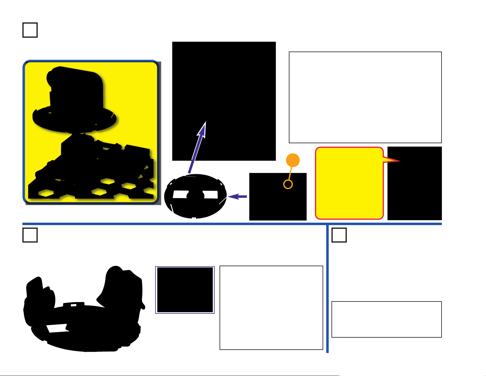
The set contains 9 prepunched cardboard
figures, which can be
inserted into slots in the
merry-go-round base.
The figures are supplied
as a single sheet; just
punch them out.
This set contains 4 prepunched cardboard discs.
These will be used to make
hypnotic patterns in project
47, with a strobe light in
project 48, and in other
projects. The discs are
supplied as a single sheet; just punch them out.
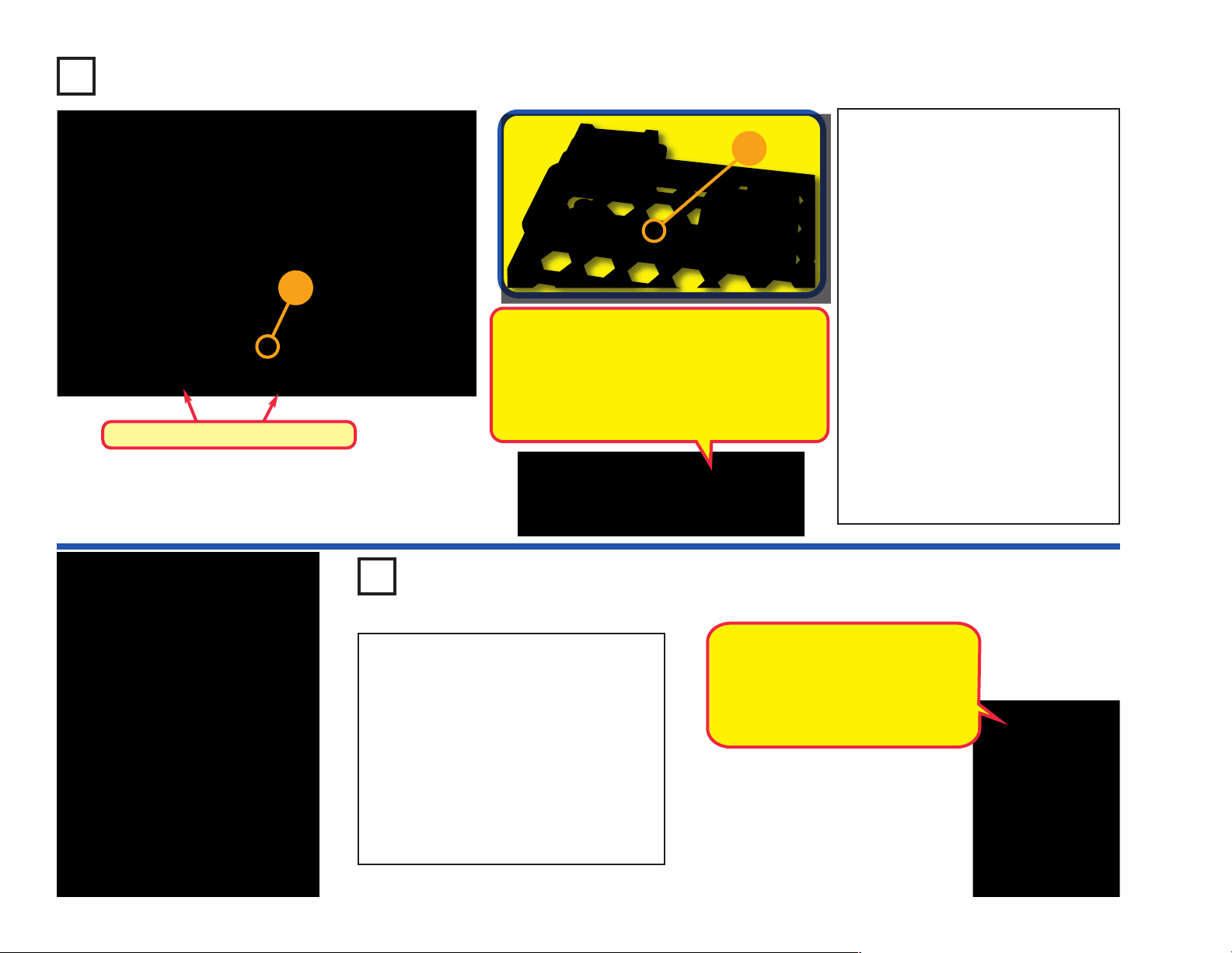
To remove a disc from the holder, flip the
holder over and poke the disc out with
your finger as shown.
-4-
Page 6

Note: The airplane is used in
project 27 and others, usually with
the light motor (M7) mounted on it.
Airplane Assembly
Step 1
3 3
3 3
1
Step 3
8
-5-
7
Step 2
2
4
4
6
9
5
9
9
Page 7

Crawler Assembly
Note: The crawler is used in project 31 and
others, usually with the geared motor (GM)
mounted on it.
Step 2
2 2
3
3
3
3
3
3
Step 1
1
4
4
4
4
4
4
1
Step 3 Step 4
2
Flat side
2
4
3
4
A
B
C
3
3
Note
direction
-6-
Page 8

Crawler Assembly
Step 5
Step 6
4 4
Step 7 Step 8
4
3
IMPORTANT: Disassembling the
crawler base is not recommended.
The 1.75” gear used in step 1 is not
needed anywhere else. The geared
motor (GM) is removable, and is
used throughout the projects.
-7-
3
4
3
Note
direction
Page 9

About Your Snap Circuits
®
Parts
(Part designs are subject to change without
notice).
BASE GRID
The base grid is a platform for mounting parts
and wires. It functions like the printed circuit
boards used in most electronic products, or like
how the walls are used for mounting the electrical
wiring in your home.
SNAP WIRES & JUMPER WIRES
The blue snap wires
are wires used to
connect components.
They are used to
transport electricity and do
not affect circuit performance.
They come in different lengths to
allow orderly arrangement of connections
on the base grid.
The red and black
jumper wires make
flexible connections for
times when using the snap wires
would be difficult. They also are
used to make connections off the base grid.
Wires transport electricity just like pipes are used
to transport water. The colorful plastic coating
protects them and prevents electricity from
getting in or out.
BATTERY HOLDER
The batteries (B1) produce an electrical voltage
using a chemical reaction. This “voltage” can be
thought of as electrical pressure, pushing
electricity through a circuit just like a pump
pushes water through pipes. This voltage is
much lower and much safer than that used in
your house wiring. Using more batteries
increases the “pressure”, therefore, more
electricity flows.
Battery Holder (B1)
SPEAKER
The speaker (SP2)
converts electricity into
sound by making
mechanical vibrations.
These vibrations create
variations in air
pressure, which travel
across the room. You
“hear” sound when your
ears feel these air
pressure variations.
SWITCHES
Switches connect (“ON”) or disconnect (“OFF”) the
wires in a circuit. When ON they have no effect on
circuit performance. Switches turn on electricity just
like a faucet turns on water from a pipe. Snap
Circuits
The slide switch (S1) is a simple switch like most in
your home.
The switcher (S6) is a more complex switch used to
reverse the wires to a component or circuit. See
project 2 for an example of connections.
One side of the vibration switch (S4) connects to a
spring, the other side connects to a wire through the
spring. When the spring is shaken, the spring
bounces to connect or disconnect the circuit.
The tilt switch (S7) has a ball that can roll to make
connections between the center and one of the sides.
®
Motion includes several different switches:
Slide Switch (S1)
Switcher (S6)
Vibration Switch (S4)
Tilt Switch (S7)
Speaker (SP2)
-8-
Page 10
About Your Snap Circuits
®
Parts
RESISTORS
Resistors “resist” the flow of electricity and are
used to control or limit the current in a circuit.
Snap Circuits
10,000W
adjustable resistor. Materials like metal have very
low resistance (<1W), while materials like paper,
plastic, and air have near-infinite resistance.
Increasing circuit resistance reduces the flow of
electricity.
Pivot Stand
The adjustable resistor (RV2) is a 10,000W
resistor but with a center tap that can be adjusted
between 200W and 10,000W.
®
Motion has two resistors (
) inside the pivot stand, and an
Adjustable Resistor (RV2)
47W and
Capacitors (C4 &C7)
MOTOR MODULES
The light motor (M7) is a motor with an LED
circuit mounted on its shaft. A motor converts
electricity into mechanical motion, in the form of
a spinning shaft. In the light motor electricity is
transported through the motor shaft to power an
LED circuit, with LEDs mounted on the fan blade.
The motor spins in both directions, but the light
circuit only works in one direction.
How does electricity turn the shaft in the motor?
Electricity is closely related to magnetism, and
an electric current flowing in a wire has a
magnetic field similar to that of a very, very tiny
magnet. Inside the motor is three coils of wire
with many loops. If a large electric current flows
through the loops, the magnetic effects become
concentrated enough to move the coils. The
motor has a magnet inside, so as the electricity
moves the coils to align them with the permanent
magnet, the shaft spins.
The air fountain (AF) has a motor and fan
inside. The fan sucks air in from the side and
pushes it out the top. As the air comes out it
spreads out like a fountain of water and can
balance light round objects like the ball.
Reversing the voltage to the air fountain reduces
the power of the airflow due to the shape of the
fan.
Air Fountain
The geared motor (GM) is a motor with a
gearbox attached. The gearbox makes the
attached “+” shaped shaft spin slower but with
more force than the shaft that is directly attached
to the motor.
CAPACITORS
The 1mF and 100mF capacitors (C7 & C4) can
store electrical pressure (voltage) for periods of
time. This storage ability allows them to block
stable voltage signals and pass changing ones.
Capacitors are used for filtering and delay
circuits.
-9-
Light Motor (M7)
Geared Motor
Page 11

About Your Snap Circuits
®
Parts
TRANSISTORS
The NPN transistor (Q2) uses a small electric
current to control a large current, and is used in
switching, amplifier, and buffering applications.
Transistors are easy to miniaturize, and are the
main building blocks of integrated circuits
including the microprocessor and memory
circuits in computers.
NPNTransistor (Q2)
LEDs
The color LED(D8) and red/yellow bicolor
LED (D10) are light emitting diodes, and may be
thought of as a special one-way light bulbs. In the
“forward” direction, (indicated by the “arrow” in
the symbol) electricity flows if the voltage
exceeds a turn-on threshold (about 1.5V for red,
slightly higher for yellow, about 2.0V for green,
and about 3.0V for blue); brightness then
increases. The color LED contains red, green,
and blue LEDs, with a micro-circuit controlling
then. The red/yellow bicolor LED contains red &
yellow LEDs in connected in opposite directions.
A high current will burn out an LED, so the
current must be limited by other components in
the circuit (though your Snap Circuits
have internal resistors to protect against incorrect
wiring). LEDs block electricity in the “reverse”
direction.
®
LEDs
LEDs (D8&D10)
ELECTRONICMODULES
The alarm IC (U2) contains a specialized sound-
generation integrated circuit (IC) and other
supporting components (resistors, capacitors,
and transistors) that are always needed with it.
A schematic for it is available at
www.snapcircuits.net/faq.
IN2
IN1
(–)
Connections:
IN1, IN2, IN3 - control inputs
(–) - power return to batteries
OUT - output connection
Connect control inputs to (+) power to make five
alarm sounds, see project 39 for an example of
proper connections.
IN3
OUT
The motion detector (U7) contains an infrared
detector, amplifier-filter circuit, and timing circuit.
A schematic for it is available at
www.snapcircuits.net/faq.
(+)
OUT
(–)
Connections:
(+) - regulated power from batteries
(–) - power return to batteries
OUT - output connection
Lens
All objects (including people and animals)
produce infrared radiation due to the heat in
them. Infrared radiation is similar to visible light
but has a longer wavelength that our eyes cannot
detect. The lens on top of the motion detector
module filters and focuses the radiation, it is most
sensitive to the radiation produced by our bodies.
Inside the motion detector module is an infrared
detector with pyroelectric crystals, which create
a tiny voltage when exposed to infrared radiation.
A circuit amplifies and filters this voltage, but only
responds to changes in the radiation level - so is
only triggered by moving objects (motion). When
motion is detected a timing circuit is used to
control other snap circuits devices for a few
seconds, such as an alarm.
-10-
Page 12

Introduction to Electricity
What is electricity? Nobody really knows. We only know how to produce it,
understand its properties, and how to control it. Electricity is the movement of subatomic charged particles (called electrons) through a material due to electrical
pressure across the material, such as from a battery.
Power sources, such as batteries, push electricity through a circuit, like a pump
pushes water through pipes. Wires carry electricity, like pipes carry water. Devices
like LEDs, motors, and speakers use the energy in electricity to do things. Switches
and transistors control the flow of electricity like valves and faucets control water.
Resistors limit the flow of electricity.
The electrical pressure exerted by a battery or other power source is called
voltage and is measured in volts (V). Notice the “+” and “–” signs on the battery;
these indicate which direction the battery will “pump” the electricity.
The electric current is a measure of how fast electricity is flowing in a wire, just
as the water current describes how fast water is flowing in a pipe. It is expressed
in amperes (A) or milliamps (mA, 1/1000 of an ampere).
The “power” of electricity is a measure of how fast energy is moving through a
wire. It is a combination of the voltage and current (Power = Voltage x Current). It
is expressed in watts (W).
The resistance of a component or circuit represents how much it resists the
electrical pressure (voltage) and limits the flow of electric current. The relationship
is Voltage = Current x Resistance. When the resistance increases, less current
flows. Resistance is measured in ohms (W), or kilo ohms (kW, 1000 ohms).
Nearly all of the electricity used in our world is produced at enormous generators
driven by steam or water pressure. Wires are used to efficiently transport this
energy to homes and businesses where it is used. Motors convert the electricity
back into mechanical form to drive machinery and appliances. The most important
aspect of electricity in our society is that it allows energy to be easily transported
over distances.
Note that “distances” includes not just large distances but also tiny distances. Try
to imagine a plumbing structure of the same complexity as the circuitry inside a
portable radio - it would have to be large because we can’t make water pipes so
small. Electricity allows complex designs to be made very small.
There are two ways of arranging parts in a circuit, in series or
in parallel. Here are examples:
Series Circuit
Parallel Circuit
Placing components in series increases the resistance; highest
value dominates. Placing components in parallel decreases the
resistance; lowest value dominates.
The parts within these series and parallel sub-circuits may be
arranged in different ways without changing what the circuit
does. Large circuits are made of combinations of smaller series
and parallel circuits.
-11-
Page 13

DOs and DON’Ts of Building Circuits
After building the circuits given in this booklet, you may wish to experiment on your
own. Use the projects in this booklet as a guide, as many important design concepts
are introduced throughout them. Every circuit will include a power source (the
batteries), a resistance (which might be a resistor, capacitor, motor, integrated circuit,
etc.), and wiring paths between them and back. You must be careful not to create
“short circuits” (very low-resistance paths across the batteries, see examples at right)
as this will damage components
alarm IC (U2) and motion detector (U7) using configurations given in the projects,
incorrectly doing so may damage them. ELENCO
damaged due to incorrect wiring.
and/or quickly drain your batteries. Only connect the
®
is not responsible for parts
Here are some important guidelines:
ALWAYS USE EYE PROTECTION WHEN EXPERIMENTING ON YOUR OWN.
ALWAYS include at least one component that will limit the current through a circuit,
such as the speaker, capacitors, ICs (which must be connected properly),
light or geared motors, air fountain, or resistors.
ALWAYS use LEDs, transistors, and switches in conjunction with other components
that will limit the current through them. Failure to do so will create a short
circuit and/or damage those parts.
ALWAYS connect capacitors so that the “+” side gets the higher voltage.
ALWAYS disconnect your batteries immediately and check your wiring if something
appears to be getting hot.
ALWAYS check your wiring before turning on a circuit.
ALWAYS connect the alarm IC (U2) and motion detector (U7) using configurations
given in the projects or as per the connection description on page 10.
NEVER connect to an electrical outlet in your home in any way.
NEVER leave a circuit unattended when it is turned on.
NEVER touch the light motor when it is spinning.
For all of the projects given in this book, the parts may be arranged in different ways without
changing the circuit. For example, the order of parts connected in series or in parallel does
not matter — what matters is how combinations of these sub-circuits are arranged together.
You are encouraged to tell us about new programs and circuits you
create. If they are unique, we will post them with your name and state
on our website at:
www.snapcircuits.net/learning_center/kids_creation
Send your suggestions to ELENCO
ELENCO®provides a circuit designer so that you can make your own
Snap Circuits
downloaded from:
www.snapcircuits.net/learning_center/kids_creation
or through the www.snapcircuits.net website.
®
drawings. This Microsoft®Word document can be
®
: elenco@elenco.com.
Examples of SHORT CIRCUITS - NEVER DO THESE!!!
Placing a 3-snap wire directly
across the batteries is a
SHORT CIRCUIT.
!
NEVER
DO!
!
NEVER
DO!
When the slide switch (S1) is turned on, this large circuit has a SHORT
CIRCUIT path (as shown by the arrows). The short circuit prevents any
other portions of the circuit from ever working.
!
NEVER
DO!
WARNING: SHOCK HAZARD - Never connect Snap Circuits
to the electrical outlets in your home in any way!
!
Warning to Snap Circuits®owners: Do not connect
additional voltage sources from other sets, or you
!
may damage your parts. Contact ELENCO®if you
have questions or need guidance.
This is also a
SHORT CIRCUIT.
!
NEVER
DO!
®
-12-
Page 14

Advanced Troubleshooting
(Adult supervision recommended)
ELENCO®is not responsible for parts
damaged due to incorrect wiring.
If you suspect you have damaged parts, you
can follow this procedure to systematically
determine which ones need replacing:
(Note: Some of these tests connect an LEDdirectly
across the batteries without another component to
limit the current. Normally this might damage the
LED, however SnapCircuits
resistors added to protect them from incorrect
wiring, and will not be damaged.)
1. Color LED(D8), red/yellow bicolor LED
(D10), speaker (SP2), geared motor (GM),
and battery holder(B1):
● Place batteries in holder.
● Place the color LED directly across the
battery holder (LED + to battery +), it
should light and be changing colors.
● Place the red/yellow bicolor LED directly
across the battery holder, in both
orientations. It should light red when the
red side is to battery +, and yellow when
the yellow side is to battery +.
● “Tap” the speaker across the battery
holder contacts, you should hear static as
it touches.
● Place the geared motor directly across the
battery holder; its shaft should spin.
● If none of the above work, then replace
your batteries and repeat. If still bad, then
the battery holder is damaged. Test both
battery holders.
2. Red & black jumper
wires: Use this mini-
circuit to test each
jumper wire, the LED
should light.
®
LEDs have internal
3. Snap wires: Use this mini-circuit to test
each of the snap wires, one at a time. The
LED should light.
4. Slide switch (S1) and vibration switch
(S4): Use this mini-circuit; if the LED doesn’t
light then the slide switch is bad. Replace
the slide switch with the vibration switch;
tapping it should light the LED, or the
vibration switch is bad.
5. Light motor (M7): Build project 3. The light
motor should spin and lights in the fan blade
should make a colorful, changing pattern.
Be sure you orient the light motor as per the
drawing.
6. Air fountain (AF): Build project 6, and be
sure you have good batteries. Air blown out
of the top of the air fountain should make the
ball spin around and/or rise into the air.
7. Pivot stand resistors: The pivot stand has
resistors mounted inside; they can be tested
using the mini-circuit shown here. The
red/yellow LED (D10) should be bright and
the color LED (D8) should be very dim,
otherwise the pivot stand is damaged.
8. Adjustable resistor (RV2): Build project
133. Move the resistor control lever to both
sides. When set to each side, one LED
should be bright and the other dim;
otherwise RV2 is bad.
9. NPN transistor (Q2): Build the mini-circuit
shown here. The color LED (D8) should only
be on if the slide switch (S1) is on. If
otherwise, then Q2 is damaged.
Tilt switch (S7): Build this mini-circuit and
10.
tilt it in different directions. D10 should be on
at some tilt angles, D8 should be on at other
tilt angles, and sometimes both lights are off.
-13-
Page 15

Advanced Troubleshooting
11. Alarm IC(U2): Build project 158, and the
variants for it. Each arrangement should
produce a siren sound, or U2 is broken.
12. Motion Detector(U7): Build project 18.
The LED (D8) should light for a few
seconds on power-up and then whenever
the circuit detects motion.
13. Switcher (S6): Build this mini-circuit. The
LED (D10) should be red when S6 is in the
top position, off when S6 is in the middle
position, and yellow when S6 is in the
bottom position; otherwise S6 is broken.
1mF (C7) and 100mF (C4) capacitors:
14.
Build project 139. Touch C4 or C7 across
points A & B, then across points C & D; the
LED (D10) should flash (brightly for C4 and
dimly for C7) or the capacitor is broken.
(Adult supervision recommended)
ELENCO
®
150 Carpenter Avenue
Wheeling, IL 60090 U.S.A.
Phone: (847) 541-3800
Fax: (847) 520-0085
e-mail: help@elenco.com
Website: www.elenco.com
You may order additional / replacement
parts at: www.snapcircuits.net
-14-
Page 16

Project Listings
Project # Description Page #
1 Color Light 17
2 Reversible Light 17
3 Light Show 18
4 Dim Light Show 18
5 Vibration, Tilt, & Motion Detector 18
6 Dancing Ball 19
7 High Power Dancing Ball 19
8 Human Height Control 19
9 Double Dancer 19
10 Low Double Dancer 19
11 Vibration Light 20
12 Vibration Alarm 20
13 Tilt Sensor 20
14 Super Motion Detector 21
15 Short Spin Lights & Sound 21
16
Louder Short Spin Lights & Sound
21
Project #
29 Idling Plane 26
30 Light Plane 26
31 Crawler 27
32 Crawler with Control Light 27
33 High Speed Crawler 27
34 Crawler with On-Board Control 28
35 Crawler with Control Light 28
36 Crawler with Motion Light 28
37 Tilt Motion 29
38 Tilt Alarm 29
39 Alarm Sounds & Lights 30
40 Softer Alarms 30
41 Funky Colors Alarms 30
42 Lighthouse 31
43 Merry-Go-Round 31
44 Fast Merry-Go-Round 31
Description Page #
Project #
57 Secure Pulley 38
58 More Pulleys 38
59 Trip-Wire Lights 38
60 Triple Lights Motion 39
61 Double Lights Motion 39
62 Big Circuit 40
63 Vib Off 40
64 Audio Triple Detector 41
65 Vibration Plane 41
66 Too Much at Once? 42
67 Not Too Much at Once 43
68 Adjustable Motor & More 44
69 Adjustable Dancing Ball 44
70 Color Brightness Adjuster 45
71
72 Yellow Brightness Adjuster 45
Description Page #
Red or Yellow Brightness Adjuster
45
17 Motion Detector Light 22
18 Low Power Motion Detector 22
19 Motion Detector Alarms 23
20
21 Mini Car 24
22 Mini Car with Control Light 24
23 High Speed Car 24
24 Mini Car with On-Board Control 25
25 Mini Car with Light 25
26 Mini Car with Motion Light 25
27 It’s a Plane! 26
28 Low Power Plane 26
Merry-Go-Round Motion Detector
-15-
23
45
46
47 Hypnotic Discs 33
48 Strobe Light with Music 33
49 Slow Merry-Go-Round 34
50 Merry-Go-Round with Lights 34
51 Fun with Gears 35
52 Higher Gear Ratio 35
53 Spin Draw 35
54 Strobe Light 36
55 Make Your Own Patterns 37
56 Fun with Pulleys 37
Merry-Go-Round with Music & Light
Fast Merry-Go-Round with Music & Light
32
32
73 Double Brightness Adjuster 45
74
75
76 Dim Double Brightness Adjuster 46
77 Secret Resistors 47
78
79
80 Adjustable Volume Alarms 47
81 Double Red Siren 48
82 Double Lights Siren 48
83 Super Vibration Light 49
84 Fast Vibration Light 49
Two-Way Double Brightness Adjuster
Parallel Double Brightness Adjuster
Adjustable Alarm Sounds & Light
Stable Adjustable Alarm Sounds & Light
46
46
47
47
Page 17

Project Listings
Project # Description Page #
85 Vibration Alarms & Lights 49
86 Shaky Alarms & Lights 49
87 Reversible Merry-Go-Round 50
88 Two-Way Circuit 50
89 Low Power Two-Way Circuit 50
90 Slow Off Tilt Alarm 51
91 Slow Off Tilt Light 51
92 Switcher Fun 51
93 Adjustable Slow Off Tilt Light 52
94 Color Slow Off Tilt Light 52
95 Very Slow Off Tilt Light 52
96 Bright Slow Off Tilt Light 52
97
98 Color Slow Off Vibration Light 53
99 Very Slow Off Vibration Light 53
100 Bright Slow Off Vibration Light 53
Adjustable Slow Off Vibration Light
53
Project #
113 Super Charge & Discharge 58
114 Mini Charge & Discharge 58
115 Light Start 59
116 Double Motion 59
117 Triple Motion 60
118 Slow Triple Motion 60
119 Dominator 60
120 Lots at Once 61
121 Electrical Circle 61
122 Generator 62
123 Leverage 62
124 Generator Load 62
125 Water Alarm 63
126 Human Alarm 63
127 Draw an Alarm 63
128 Human & Water Light 64
Description Page #
Project #
141 Short Burst Machine Gun 70
142 Short Burst Sound & Lights 70
143 Short-On Light 70
144 Finger Touch Light 71
145 Slow Off Light 71
146 3-Position Switch 71
147 One Way Electricity 72
148 Tilt Sound & Light 72
149 Inflator 73
150 Transistor 73
151 Slow Light 74
152 Wiggler 74
153 Blinker Beeper 75
154 Blinker Blinker 75
155 Blinker Control 75
156 Red Lights First 76
Description Page #
101 Slow Off Tilt Lights 54
102 Very Slow Off Tilt Lights 54
103 Slow Off Vibration Lights 54
104 Very Slow Off Vibration Lights 54
105 Tilted Motion Detector 55
106 Tilt Off 55
107 Electricity In, Electricity Out 56
108 Little Electricity In/Out 56
109 Mini Rechargeable Battery 56
110 Mini Rechargeable Batteries 57
111 Left Right Bright Lights 57
112 Charge & Discharge 58
129 Conduction Detector 64
130 Trip-Wire Alarm 64
131 Current Limiters 65
132 Current Limiters in Parallel 65
133 Current Director 66
134 Reversible Current Director 67
135 Lazy Fan 68
136 Lazy Merry-Go-Round 68
137 Lazy Lights 68
138 Very Lazy Lights 68
139
140
Electricity You Can Walk Away With
Electricity You Can Walk Away With (II)
69
69
157 Red Just Before Yellow 76
158 Loud Sirens 77
159 Adjustable Volume Sirens 77
160 Capacitors in Series 78
161 Capacitors in Parallel 78
162 Adjustable Low Speed Fan 79
163 Adjustable Light Motor 79
164 Transistor Control 80
165 Reversible Motor 80
166 Slow Reversible Motor 80
167 Orange Light 81
168 Light, Sound, & Flight 81
-16-
Page 18
Project 1 Color Light
+
Placement Level Numbers
+
Snappy says the color LED actually contains
separate red, green, and blue lights, with a
micro-circuit controlling them.
The pivot stand is used here because it has
internal resistors that limit the flow of electricity,
and help protect the color LED from damage.
Snap Circuits®uses electronic blocks
that snap onto a clear plastic grid to
build different circuits. These blocks
have different colors and numbers on
them so that you can easily identify
them.
Build the circuit shown on the left by
placing all the parts with a black 1 next
to them on the board first. Then,
assemble parts marked with a 2. Install
two (2) “AA” batteries (not included)
into each of the battery holders (B1) if
you have not done so already.
Turn on the slide switch (S1), and
enjoy the light show from the color LED
(D8). For best effects, dim the room
lights.
Try replacing the color LED with the
red/yellow bicolor LED (D10), orienting
it in either direction.
-17-
Project 2 Reversible Light
Build the circuit as shown, turn on the slide
switch (S1), and then set the switcher (S6)
at each of its 3 positions. The red/yellow
bicolor LED (D10) should be yellow at the
top S6 position, off at the middle position,
and red at the bottom S6 position. For best
effects, dim the room lights.
Try replacing the red/yellow bicolor LED
with the color LED (D8, “+” on left). The
color LED isn’t bidirectional, so it only
works at the top S6 position.
LEDs are light emitting diodes, which
are like little light bulbs that only work
in one direction. The red/yellow
bicolor LED is actually a red LED and
a yellow LED, connected in opposite
directions inside the same part.
Page 19
Project 3 Light Show
Project 4
+
Placement Level Numbers
WARNING: Moving parts. Do not
!
touch the fan during operation.
Project 5 Vibration, Tilt, &
Snap Circuits®uses electronic blocks that snap onto a clear
plastic grid to build different circuits. These blocks have different
colors and numbers on them so that you can easily identify them.
Build the circuit shown on the left by placing all the parts with a
black 1 next to them on the board first. Then, assemble parts
marked with a 2. Install two (2) “AA” batteries (not included) into
each of the battery holders (B1) if you have not done so already.
Turn on the slide switch (S1) and watch the light show! For best
effects, dim the room lights.
Never touch the fan while it is spinning.
The fan on the light motor has
several LEDs, similar to the
ones in the D8 & D10 LEDs.
Electricity is transported
through the motor shaft to
power the LEDs.
Motion Detector
Dim Light
Show
Use the preceding circuit, but
replace one of the battery holders
(B1) with a 3-snap wire. The circuit
works the same but is much
dimmer, giving some interesting
effects. For best effects, view in a
dimly lit room.
Build the circuit and turn on the slide switch (S1). The color LED (D8)
lights for a few seconds on start-up, and then whenever the circuit
detects motion, feels vibration, or is tilted in some directions.
-18-
Page 20

Project 6
Place the spout
on top of the air
fountain and the
ball in the air flow.
Spout
Dancing Ball
Build the circuit as shown,
place the spout on the air
fountain (AF), turn on the slide
switch (S1), then place the
ball directly in the blowing air
above the air fountain. The
blowing air should balance
the ball, so it floats in the air
and “dances”. Occasionally
the ball may become unstable
and fall out; just place it back
into the air flow.
If desired, you may draw lines
or patterns on the ball. New
alkaline batteries are
recommended for this project.
Project 7
High Power Dancing Ball
Use the preceding circuit, but replace the 3-snap wire with a second
battery holder (B1). The circuit works the same but the blowing air flow
is stronger, making the ball float higher but also making it unstable. As
a result, the ball may fall out quickly.
Try replacing the ball with other small, light balls in your home and see
which ones float in the airflow.
Project 8
Human Height Control
Use the preceding circuit, but place your fingers or thumb in front of the
air intake on the side of the air fountain, to partially block it. You can
make the ball float lower in the air by restricting the airflow. This may
make the ball be more stable and stay in the air longer.
-19-
Project 9 Double Dancer
Build this circuit, turn on the slide switch (S1), set the
switcher (S6) to either the top or bottom position, and
place the ball in the air flow above the spout on the air
fountain (AF). See how long the ball floats in the air
for each S6 setting.
The top S6 setting has stronger air flow, but it may be
too strong, causing the ball to become unstable and
fall out. The bottom S6 setting makes the air flow a
little weaker, so the ball may be more stable and float
in the air better.
Try replacing the ball with other small, light balls in
your home and see which ones float in the airflow.
The air is being blown by a fan blade inside the
air fountain. The switcher (S6) reverses the
direction that the fan spins, but the shape of the
fan makes the air flow stronger in one direction.
Project 10
Low Double
Dancer
Use the preceding circuit, but
replace one of the battery
holders with a 3-snap wire. The
circuit works the same but the
blowing air flow is weaker. The
ball may wiggle around without
rising into the air.
Page 21

Project 11
Vibration Light
Project 12
Build the circuit as shown. Tap on the
vibration switch (S4) or bang on the table
to make the red/yellow LED (D10) light.
One side of the vibration switch connects
to a spring, and the other side connects to
a contact next to the spring. When the
switch is shaken, the spring bounces to
open or close the circuit.
Project 13
Vibration Alarm
Build the circuit as shown. Tap on the vibration switch (S4)
or bang on the table to sound an alarm.
Tilt Sensor
Build the circuit as shown and turn on the slide switch (S1). The color
LED (D8) or red/yellow LED (D10) will light if the circuit is tilted or
moved. Experiment to see which tilt angles activate which LED.
If the circuit does not shut off when left alone on a flat surface, then tilt
it slightly so it turns off.
The tilt switch (S7)
contains a ball, which
activates contacts when
it rolls to either side due
to tilt or motion.
-20-
Page 22

Project 14
Mount circuit on the blue stand and face across a room.
Super Motion Detector
Assemble the circuit and place the base grid into the blue stand (with
the NPN transistor (Q2) closest to the stand) and carefully stand it up.
Position it near the edge of a table, facing across a room.
Turn on the slide switch (S1). The color LED (D8) lights and an alarm
sounds for a few seconds on start-up, and then whenever the circuit
detects motion in the room.
This circuit will work in the dark, but be careful not to hurt yourself
moving around a room in the dark.
Objects that generate heat, including
people and animals, also produce
infrared radiation. Infrared radiation
cannot be seen with our eyes, but
can be detected.
The motion detector (U7) is designed
to detect changes in infrared radiation,
especially the type emitted by people.
The NPN transistor (Q2) acts as an
amplifier, helping the motion detector
turn on the color LED and alarm.
Project 15
-21-
Short Spin Lights & Sound
Build the circuit and turn on the
slide switch (S1). The light
motor (M7) spins in short bursts,
synchronized with a machine
gun-like sound.
This is one of my
favorite circuits!
Project 16
Louder Short
Spin Lights &
Sound
Use the preceding circuit but
replace the color LED (D8) with a
3-snap wire. The sound is louder
now, and the movement of the light
motor (M7) is a little different.
Page 23

Project 17 Motion Detector Light
Assemble the circuit and place the base grid into the blue stand (with
the NPN transistor (Q2) closest to the stand) and carefully stand it up.
Position it near the edge of a table, facing across a room.
Turn on the slide switch (S1). The color LED (D8) lights for a few
seconds on start-up, and then whenever the circuit detects motion in
the room.
This circuit will work in the dark, but be careful not to hurt yourself
moving around a room in the dark.
Mount circuit on the blue stand and face across a room.
Project 18 Low Power
Motion Detector
Place the base grid into the blue stand (with the slide switch (S1) closest
to the stand) and carefully stand it up. Position it near the edge of a table,
facing across a room.
Turn on the slide switch (S1). The color LED (D8) lights for a few seconds
on start-up, and then whenever the circuit detects motion in the room.
The color LED will not be as bright as it
was in the preceding circuit, because this
circuit does not have the NPN transistor
(Q2) as an amplifier. This circuit uses less
electricity than projects 14 & 17, so your
batteries will last longer.
Mount circuit on the blue stand and face across a room.
-22-
Page 24

Project 19
Motion Detector Alarms
Assemble the circuit and place the base grid into the blue stand (with
the slide switch (S1) closest to the stand) and carefully stand it up.
Position it near the edge of a table, facing across a room.
Turn on the slide switch (S1). An alarm sounds for a few seconds on
start-up, and then whenever the circuit detects motion in the room.
This circuit will work in the dark, but be careful not to hurt yourself
moving around a room in the dark.
Variant A: Add a connection between the points marked B & C using
a 1-snap and a 2-snap. Now it sounds like a machine gun.
Variant B: Remove the connection between B & C, and add a
connection between A & B. Now it sounds like a fire engine.
Variant C: Remove the connection between A & B, and add a
connection between A & D. Now it sounds like a European siren.
Project 20 Merry-Go-Round
-23-
Motion Detector
Assemble the circuit and mount the merry-go-round base on the geared
motor (GM) shaft. Place cardboard figures on the merry-go-round if
desired.
Turn on the slide switch (S1). The merry-go-round spins for a few
seconds on start-up, and then whenever the circuit detects motion in
the room.
Page 25

Rubber rings
Project 21
Mini Car
Build the circuit as shown. Mount the
1.75” gear on the geared motor (GM) with
the rubber rings to keep it from sliding out
of position, place it on the mini car frame,
and connect it to the circuit using the red
& black jumper wires. Turn on the slide
switch (S1), and then use the switcher
(S6) to make the mini car go forward,
backward-turning, or stop. You can follow
the car around the room or table carrying
the base grid while using S6 to control it.
Be careful to follow it closely so you don’t
over-extend the jumper wires, and to keep
it from falling off the table.
Project 22
Mini Car with Control Light
Modify the preceding circuit
to include the red/yellow
bicolor LED (D10), which
lights yellow when the car is
going forward, or red when
it goes backward-turning.
Project 23
High Speed
Car
Modify the preceding circuit
to use a second battery
holder (B1), as shown. The
car is much faster now, but
more difficult to control.
-24-
Page 26

Project 24
Mini Car with
Project 25
Rubber
rings
Project 26
On-Board Control
Build the circuit shown here. Mount the 1.75” gear
on the geared motor (GM) with the rubber rings to
keep it from sliding out of position, and place it on
the mini car frame. Place the switcher (S6) directly
on the geared motor, set S6 to the middle position,
place a battery holder (B1) on the front of the mini
car frame, connect the red jumper wire from + on
B1 to C on S6, then connect black wire from — on
B1 to B on S6. Be sure the jumper wires will not
interfere with the gears or wheels.
Set S6 to the “A” side to make the mini car go
forward, or set it to the “D” side to make the mini
car go backwards and turn. Be careful that the mini
car does not fall off a table or down a stairway!
Mini Car with Motion Light
Mini Car
with Light
Add the color LED (D8) directly
on top of the jumper wire
connections to the battery holder
(B1, LED + to battery +).
Alternately, you can use the
red/yellow bicolor LED (D10),
oriented in either direction.
Remove the LED when you are
finished. Note that normally
connecting an LED directly to a
battery can damage the LED, but
the color LED has an internal
resistor that will protect it.
-25-
Rubber
rings
Mount the 1.75” gear on the geared motor (GM), with
the rubber rings to keep it from sliding out of position,
and place it on the mini car frame. Mount the
red/yellow bicolor LED (D10), vibration switch (S4),
and pivot stand to the geared motor in the
arrangement shown, and connect to the circuit on the
base grid using the red & black jumper wires as
shown.
Turn on the slide switch (S1), and then use the
switcher (S6) to make the mini car go forward,
backward-turn, or stop. When the mini car is moving,
vibrations will often light the red/yellow LED. You can
follow the mini car around the room or table carrying
the base grid while using S6 to control it. Be careful
to follow it closely so you don’t over-extend the
jumper wires, and to keep it from falling off the table.
Page 27

Project 27
It’s a Plane!
Project 28
Low Power
WARNING: Moving parts. Do not
!
touch the fan during operation.
Project 29
Idling Plane
Assemble the airplane using the
instructions on page 5, install the
light motor (M7) into the front of it,
build the circuit shown here, and
connect the red & black jumper
wires to the light motor (red to “+”).
Spread out the jumper wires and
be sure they will not interfere with
the fan on the light motor.
Place the airplane on a smooth
surface and turn on the slide
switch (S1). The fan on the light
motor spins and lights, and the
airplane slowly moves around due
to vibration.
Project 30
Use this circuit, mount the color LED (D8) on the airplane and the red &
black jumper wires to it (red to “+”).
Turn on the slide switch (S1) and the LED shines. The plane will not move.
Use the preceding circuit, but
replace one of the battery holders
(B1) with a 3-snap wire. The
circuit works the same but is
much dimmer, giving some
interesting effects. For best
effects, view in a dimly lit room.
Light Plane
Plane
Use either of the two preceding circuit, but replace the light motor (M7)
with the geared motor (GM). Place the 2.55” gear on the “+” shaft of the
geared motor, and mount the geared motor on the plane as shown.
Turn on the slide switch (S1) and the gear spins like a propellor. The plane
appears to be idling with the motor running, and getting ready to take off.
-26-
Page 28

Project 31 Crawler
Assemble the crawler using the assembly
instructions on pages 6 and 7, and build the circuit
shown here. Mount the smallest gear (1.0”) on the
geared motor (GM) with a rubber ring to keep it
from sliding out of position, place it on the crawler
frame, and connect it to the circuit using the red &
black jumper wires.
Turn on the slide switch (S1), and then use the
switcher (S6) to make the crawler go forward,
backward, or stop. You can follow the crawler
around the room or table carrying the base grid
while using S6 to control it. Be careful to follow it
closely so you don’t over-extend the jumper wires,
and to keep it from falling off the table. The crawler
Rubber ring
does not turn.
-27-
Project 32
Crawler with
Control Light
Modify the preceding circuit
to include the red/yellow
bicolor LED (D10), which
lights yellow when the
crawler is going forward, or
red with it goes backward.
Project 33
High
Speed
Crawler
Modify the preceding circuit
to use a second battery
holder (B1), as shown. The
crawler is much faster now.
Page 29

Project 34
Crawler with On-Board Control
Project 35
Rubber ring
Project 36
Rubber ring
Assemble the crawler using the assembly
instructions on pages 6 and 7, and build the
circuit shown here. Mount the smallest gear
(1.0”) on the geared motor (GM) with a rubber
ring to keep it from sliding out of position.
Place it on the crawler frame, place the
switcher (S6) directly on the geared motor,
set S6 to the middle position, place a battery
holder (B1) on the front of the crawler frame,
connect the red jumper wire from + on B1 to
C on S6, then connect black wire from - on
B1 to B on S6. Be sure the jumper wires will
not interfere with the gears or legs. Be careful
that the crawler does not fall off a table or
down a stairway! The crawler does not turn.
Set S6 to the “A” side to make the crawler go
forward, or set it to the “D” side to make the
crawler go backwards.
Crawler
with Light
Add the color LED (D8) directly on
top of the jumper wire connections
to the battery holder (B1, LED + to
battery +). Alternately, you can use
the red/yellow bicolor LED (D10),
oriented in either direction.
Remove the LED when you are
finished. Note that normally
connecting an LED directly to a
battery can damage the LED, but
the color LED has an internal
resistor that will protect it.
Crawler with Motion Light
Assemble the crawler using the assembly instructions
on pages 6 and 7, and build the circuit shown here.
Mount the smallest gear (1.0”) on the geared motor
(GM) with a rubber ring to keep it from sliding out of
position, and place it on the crawler frame. Mount the
red/yellow bicolor LED (D10), vibration switch (S4), and
pivot stand to the geared motor in the arrangement
shown, and connect to the circuit on the base grid using
the red & black jumper wires as shown.
Turn on the slide switch (S1), and then use the
switcher (S6) to make the crawler go forward,
backward, or stop. When the crawler is moving,
vibrations will often light the red/yellow LED. You can
follow the crawler around the room or table carrying
the base grid while using S6 to control it. Be careful
to follow it closely so you don’t over-extend the jumper
wires, and to keep it from falling off the table. The
crawler does not turn.
-28-
Page 30

Project 37
Tilt Motion
Assemble the circuit and mount the merry-go-round base on
the geared motor (GM) shaft. Place cardboard figures on the
merry-go-round if desired.
Turn on the slide switch (S1). The merry-go-round or light
motor start if the circuit is tilted or moved. Experiment to see
which tilt angles activate which effects.
If the circuit does not shut off when left alone, then tilt it slightly
so it turns off.
WARNING: Moving parts. Do not
!
touch the fan during operation.
-29-
Project 38
Tilt Alarm
Build the circuit and turn on the slide switch (S1). An alarm sounds if
the circuit is moved, or tilted in some directions.
If the circuit does not shut off when left alone on a flat surface, then tilt
it slightly so it turns off.
Next, move the 3-snap wire from the points marked A & B to the points
marked C & D. Now it is sensitive to tilt in different directions.
If you place 3-snap wires across A & B, and C & D, then the circuit will
be so sensitive to tilt that the alarm may be difficult to shut off.
Page 31

Project 39
Alarm Sounds & Lights
Build the circuit and turn on the slide switch (S1). An alarm sounds and
a light comes on.
Add a connection between the points marked D & E using a 1-snap and
a 2-snap. Now it sounds like a machine gun.
Remove the connection between D & E, and add a connection between
B & D. Now it sounds like a fire engine.
Remove the connection between B & D, and add a connection between
B & F. Now it sounds like a European siren.
Remove the connections between B & F and C & D, and add a
connection between A & B. See what it sounds like now.
Project 40
Softer Alarms
Modify the preceding
circuit to be this one. It
works the same way,
except that it isn’t as loud.
Try the same variants as
for the preceding circuit.
Project 41
Funky Colors
Alarms
Use the preceding circuit, but replace
the red/yellow bicolor LED (D10) with
the color LED (D8, “+” on right). Try all
the same variants as for the preceding
two circuits. You should see some
interesting effects in the color LED’s
colors.
-30-
Page 32
Project 42
Lighthouse
Build this circuit and mount the merry-go-round base
onto the shaft on the geared motor (GM). Next, place
the color LED (D8) directly across the snaps on the
other battery holder (B1) as shown; the color LED
starts flashing. Now place that battery holder into the
slot in the merry-go-round base. Turn on the slide
switch (S1), and the color LED spins, shining its light
around the room like a lighthouse! For best effects,
turn off or dim the room lights.
Disconnect the color LED from the battery holder when
you are finished, to avoid draining your batteries.
Normally connecting
+
an LED directly to a
battery can damage
the LED, but the LEDs
in this set (D8 & D10)
have internal resistors
to protect them from
incorrect wiring, and
will not be damaged.
-31-
Project 43
Merry-Go-Round
Use the preceding circuit, but insert
some of the cardboard figures into
the 3 slots on the edge of the merrygo-round base (the figures may
need to be punched out of a
cardboard sheet).
You may also mount the color LED
(D8) in the other battery holder (B1)
as done in the preceding circuit, to
have a light in the merry-go-round.
Project 44
Fast Merry-
Go-Round
Use the preceding circuit, but replace
the 3-snap wire with the second
battery holder (B1). Now the merry-goround spins faster.
Page 33

Project 45 Merry-Go-Round with
Music & Light
Insert some of the cardboard figures into
the 3 slots on the edge of the merry-goround base (the figures may need to be
punched out of a cardboard sheet). Build
this circuit and mount the merry-goround base onto the shaft on the geared
motor (GM).
Turn on the slide switch (S1) and watch
the show!
You can change the sound by removing
the 1-snap and 2-snap wires that are at
point A, or by moving them to be across
points B & C, or across points A & D.
Project 46 Fast Merry-Go-Round
with Music & Light
Insert some of the cardboard figures into
the 3 slots on the edge of the merry-goround base (the figures may need to be
punched out of a cardboard sheet). Build
this circuit and mount the merry-goround base onto the shaft on the geared
motor (GM).
Turn on the slide switch (S1) and watch
the show!
You can change the sound by removing
the 1-snap and 2-snap wires that are at
point A, or by moving them to be across
points B & C, or across points A & D.
-32-
Page 34

Project 47
Project 48
Hypnotic Discs
Use the preceding circuit (Fast Merry-Go-Round
with Music & Light), but remove the cardboard
figures from the merry-go-round base and install
one of the colored discs into the base. Watch the
hypnotic patterns on the discs as they spin.
Tab Tab
Tab
Slide tabs into slots.
Here are some effects to watch for:
With this disc, the white
lines are often visible
despite spinning so fast,
and some colors
sometimes seem to
disappear.
When red flashes on the
LED, the red spiral
pattern seems to
disappear. This pattern
can seem hypnotizing.
Modify the preceding circuit to be this one; which has the color LED (D8) connected
with the red & black jumper wires, and the 1mF capacitor (C7) placed where the
color LED had been. Install one of the colored discs into the merry-go-round base.
For best effects, do this in a dimly lit room. Turn on the slide switch (S1). Hold the
color LED upside down over the merry-go-round base so it shines on the spinning
disc.
Observe the effects as the color LED flashes on the disc as it spins. Try it with
different discs.
Variants: You can change the sound by removing the 1-snap and 2-snap wires that
are at point A, or by moving them to be across points B & C, or across points A & D.
Strobe Light with Music
Tab Tab
Tab
Slide tabs into slots.
Hold color LED (D8)
over disc as shown.
With this disc, some
colors seem to disappear
at times.
-33-
This pattern can seem
hypnotizing.
If the color LED flash rate is synchronized with the disc rotation speed, it can appear
to “freeze” parts of the spinning disc pattern. Also, as different colors flash, those
colors can seem to disappear.
More about this in project 54, which uses gears to spin the disc faster and has
adjustable speed, but does not have music.
The 1mF capacitor is used to filter the voltage to the color LED. Without it, electrical
disturbances from the speaker and geared motor would disrupt the color LED’s
flashing pattern.
Page 35

Project 49 Slow Merry-Go-Round
Insert some of the cardboard figures into the 3 slots
on the edge of the merry-go-round base (the figures
may need to be punched out of a cardboard sheet).
Build this circuit and mount the merry-go-round base
onto the shaft on the geared motor (GM).
Turn on the slide switch (S1), and adjust the speed
of the merry-go-round using the lever on the
adjustable resistor (RV2). Most of the speed control
will be over a small part of RV2’s adjustment range.
Project 50 Adjustable Merry-Go-
Round with Lights
Modify the preceding circuit to make this one. Set the lever on the
adjustable resistor (RV2) to the top. Turn on the slide switch (S1), and
use the lever on the adjustable resistor to set the brightness of the LEDs
(D8 & D10) and the speed of the merry-go-round base.
This circuit uses the NPN transistor (Q2) and
adjustable resistor (RV2) to control the speed
of the geared motor (GM). A small electric
current into the transistor through RV2 and the
LED (D10) controls a larger current into the
transistor through the geared motor. RV2
cannot be used to control the geared motor
directly, because its high resistance would
prevent the geared motor from operating.
-34-
Page 36

Project 51 Fun with Gears
If gear slides down “+” shaft during use
then add a rubber ring to keep it in place.
Ledge must be
on bottom side
Build the circuit shown. Mount the 1.75” gear on the geared motor (GM), mount
the 2.55” gear on the “+” shaped bar, place the “+” bar into the pivot stand,
and then align the position of the 2.55” gear on the “+” shaft so the teeth of
both gears mesh. Either insert some of the cardboard figures into the 3 slots
on the edge of the merry-go-round base, or install one of the colored discs into
the base. Mount the merry-go-round base onto the top of the “+” shaped bar.
Turn on the slide switch (S1), and notice how fast the merry-go-round (or disc)
is spinning. If the gear slides down the “+” bar during use then add a rubber
ring to keep it in place.
Part B: Swap the positions of the 1.75” and 2.55” gears, so that the larger gear
is on the geared motor and the smaller one is on the “+” shaped bar. Notice
how much faster the merry-go-round is spinning now. Compare the size
difference between the gears to how much faster one is spinning.
Part C: Remove the pivot stand and mount the merry-go-round base directly
on the geared motor. Compare the speed to how it was when using the gears.
Part D: Try replacing the 3-snap wire with a second battery holder (B1). This
can be done with any of the above gear arrangements. The additional battery
voltage makes things spin faster.
Gears can be used to make things spin faster or slower. When
one gear has more teeth than another, it will spin slower. Using
gears to reduce rotation speed also increases the turning force,
allowing it to overcome more friction. Using gears also changes
the direction of rotation.
Inside the geared motor (GM) is a motor spinning very fast, but
with little force (much too little to spin the merry-go-round). Several
small gears connect the motor to the white “+” shaped shaft; these
reduce the rotation speed, giving the shaft enough force to spin
the merry-go-round, and also making it easier to control.
-35-
Project 52
Use the preceding circuit, but replace the 1.75” and 2.55”
gears with the 1.0” (smallest) and 3.3“ (largest) gears. Try
it both ways:
Part A: With the smallest gear on the geared motor and
the largest gear on the pivot stand, the merry-go-round (or
disc) should spin very slow. Compare the size difference
between the gears to how much faster one is spinning.
Part B: With the largest gear on the geared motor and the
smallest gear on the pivot stand, the merry-go-round (or
disc) should spin very fast.
Higher Gear Ratio
Note: You cannot use the
1.0” or 3.3” gears with the
1.75” or 2.55” gears,
because you cannot get
the proper spacing
needed for their teeth to
mesh well enough.
Project 53
Spin Draw
Use either of the preceding two circuits, with any of the
described gear combinations. Cut a piece of white paper to the
same size as one of our discs, or use the back of our discs.
Put them in the merry-go-round base and spin it.
Take a soft marker and GENTLY touch it on the spinning disc.
Move it around to draw patterns on the disc. Try starting in the
middle and slowly moving your marker outward. Be careful not
to use too much force or you could damage your parts.
Page 37

Tab Tab
Tab
Slide tabs into slots.
Project 54 Strobe Light
Ledge must be
on bottom side
If gear slides down “+” shaft during use
then add a rubber ring to keep it in place.
Build the circuit shown. Mount the 3.3” gear on the geared motor
(GM), mount the 1.0” gear on the “+” shaped bar, place the “+”
bar into the pivot stand, and then align the position of the 1.0” gear
on the “+” shaft so the teeth of both gears mesh. Install one of the
colored discs into the merry-go-round base. Mount the merry-goround base onto the top of the “+” shaped bar. Connect the color
LED (D8) using the red & black jumper wires.
For best effects, do this in a dimly lit room. Turn on the slide switch
(S1). Hold the color LED upside down over the merry-go-round
base so it shines on the spinning disc. Vary the spin speed using
the lever on the adjustable resistor (RV2). If the gear slides down
the “+” bar during use then add a rubber ring to keep it in place.
Observe the effects as the color LED flashes on the disc as it
spins. Try it with different discs.
If desired, you can replace the 1.0” gear with the 1.75” gear, and
replace the 3.3” gear with the 2.55” gear. The disc will spin more
slowly now.
If the color LED flash rate is synchronized
with the disc rotation speed, it can appear
to “freeze” parts of the spinning disc
pattern. Also, as different colors flash,
those colors can seem to disappear.
The 1mF capacitor is used to filter the
voltage to the color LED. Without it,
electrical disturbances from the speaker
and geared motor would disrupt the color
LED’s flashing pattern.
Hold color LED (D8)
over disc as shown.
Here are some effects to watch for:
With this disc, the white
lines are often visible
despite spinning so fast,
and some colors
sometimes seem to
disappear.
With this disc, some
colors seem to disappear
at times.
When red flashes on the
LED, the red spiral
pattern seems to
disappear. This pattern
can seem hypnotizing.
This pattern can seem
hypnotizing.
-36-
Page 38

Project 55
Project 56 Fun with Pulleys
Make Your
If pulley slides down “+” shaft during use
then add a rubber ring to keep it in place.
Ledge must be on bottom side
Own Patterns
Draw your own patterns on paper
or cardboard, then cut them to the
same size as our discs. You can
also draw patterns on the backs of
our discs. Put them in the merrygo-round base and repeat the
preceding project. Have a contest
with your friends to see who can
make the most interesting hypnotic
or strobe effects! You can also find
lots of fun patterns and visual
illusions by doing a search on the
internet.
Build the circuit shown. Mount the 0.9” pulley on the geared motor (GM), mount the 1.3” pulley on the “+”
shaped bar, place the “+” bar into the pivot stand, and then align the position of the 1.3” pulley on the “+”
shaft so it is the same height as the 0.9” pulley. Place the rubber band around both pulleys. Either insert
some of the cardboard figures into the 3 slots on the edge of the merry-go-round base, or install one of
the colored discs into the base. Mount the merry-go-round base onto the top of the “+” shaped bar.
Turn on the slide switch (S1), and notice how fast the merry-go-round (or disc) is spinning. If the
pulley slides down the “+” bar during use then add a rubber ring to keep it in place.
Part B: Swap the positions of the 0.9” and 1.3” pulleys, so that the larger pulley is on the geared
motor and the smaller one is on the “+” shaped bar. Notice how much faster the merry-go-round is
spinning now. Compare the size difference between the pulleys to how much faster one is spinning.
Part C: Remove the pivot stand and mount the merry-go-round base directly on the geared motor.
Compare the speed to how it was when using the pulleys.
Part D: Try replacing the 3-snap wire with a second battery holder (B1). This can be done with any
of the above gear arrangements. The additional battery voltage makes things spin faster.
Part E: Replace the rubber band with one from your home, and change the location of the pivot stand on
the base grid so there is tension in your rubber band. Don’t make the band too tight, because then the
snaps on the pivot stand may not be able to hold it in place. Turn on the circuit and see how well it works.
Note: If the pivot stand comes off the base grid due to the tension of the rubber band, see the next
project for help.
Pulleys can be used to make things spin faster or
slower. When one pulley is larger than another, it will
spin slower. Using pulleys to reduce rotation speed
also increases the turning force, allowing it to
overcome more friction.
Pulley transfer power across small distances, because
the pulleys are separated by a small gap, such as that
between the geared motor and pivot stand here.
It is important to have the proper tension in the rubber
band (or other material) attached between the pulleys.
If there is too much tension, energy is lost and there is
too much strain on the shafts and band, so these soon
break. If there too little tension in the band, the band
may start slipping or fall off. The bands used with pulleys
are typically made of durable materials like nylon.
-37-
Page 39

Project 57
Secure Pulley
If pulley slides down “+” shaft during use
then add a rubber ring to keep it in place.
Project 58
More Pulleys
Ledge must be on bottom side
In the preceding project, tension in the rubber band
pulls on the “+” shaped bar and pivot stand, and may
pull the pivot stand snaps off the base grid. If so, modify
the circuit to be the one shown here, which uses
additional parts (S4, Q2, and C7) to help hold and
secure the pivot stand in place. In part E, when
repositioning the pivot stand to use your own rubber
band, you can reposition S4, Q2, and C7 to help hold
the pivot stand in its new location.
This circuit is electrically the
same as the preceding one.
Parts S4, Q2, and C7 are only
used to help hold the pivot
stand in place, and have no
electrical function.
Project 59 Trip-Wire
Lights
Repeat projects 56/57, but replace each of
the pulleys with the larger 2.1” pulley. Try
this both with the 2.1” pulley on the pivot
stand, and then with it in the geared motor.
Also try it with your own rubber band, as
described in Part E of project 48.
With the large 2.1” pulley on the pivot
stand and the small 0.9” pulley on the
geared motor, the merry-go-round (or
disc) spins very fast. With the small 0.9”
pulley on the pivot stand and the large
2.1” pulley on the geared motor, the
merry-go-round (or disc) spins very slow.
Build the circuit shown and turn
on the slide switch (S1). Nothing
happens. Break the black jumper
wire connection and lights flash.
You could replace the black
jumper wire with a longer wire
and run it across a doorway to
signal an alarm when someone
enters.
You can reverse the red/yellow
bicolor LED (D10) to change its
color. The adjustable resistor
(RV2) is used here as a fixed
resistor, so moving its lever won’t
do anything.
-38-
Page 40

Project 60 Triple Lights Motion
Assemble the airplane using the instructions on page 5,
install the light motor (M7) into the front of it, build the
circuit shown here, and connect the red & black jumper
wires to the light motor (red to “+”). Place the airplane on
a smooth surface and spread out the jumper wires and be
sure they will not interfere with the fan on the light motor.
Mount the merry-go-round base onto the shaft on the
+
WARNING: Moving parts. Do not
!
touch the fan during operation.
geared motor (GM). Next, place the color LED (D8)
directly across the snaps on the other battery holder (B1)
as shown; the color LED starts flashing. Now place that
battery holder into the slot in the merry-go-round base.
Turn on the slide switch (S1).
The color LED spins, shining its light around the room like
a lighthouse. The fan on the light motor spins and lights
dimly, and the airplane slowly moves around due to
vibration. Move the switcher (S6) switch back and forth to
make the red/yellow bicolor LED (D10) change colors.
Disconnect the color LED from the battery holder when
you are finished, to avoid draining your batteries.
-39-
Project 61
Double Lights Motion
Note: there is no middle snap on the geared motor here.
Modify the preceding circuit by removing the color LED
(D8) and adding the second battery holder (B1) to the
circuit as shown. Either insert some of the cardboard
figures into the 3 slots on the edge of the merry-goround base, or install one of the colored discs into the
base. Mount the merry-go-round base onto the shaft on
the geared motor (GM). Turn on the slide switch (S1).
The fan on the light motor spins and lights, and the
airplane slowly moves around due to vibration. Move
the switcher (S6) back and forth to make the
red/yellow bicolor LED (D10) change colors.
Page 41

Project 62
Big Circuit
WARNING: Moving parts. Do not
!
touch the fan during operation.
+
Place the spout
on top of the air
fountain and
the ball in the
air flow.
Spout
Mount a green gear on the geared
motor, a matching gear and the on
the “+” shaped bar, place the bar in
the pivot stand and align the gears,
place a colored disc or figures on
the merry-go-round base and
mount it on the “+” bar. If gear
slides down shaft during use then
add a rubber ring to keep it in
place.
Build the circuit as shown. Place the spout and ball
on the air fountain (AF). Place one of the green
gears on the geared motor (GM). Mount a matching
green gear on the “+” shaped bar with a rubber ring
to keep it in position, place the bar in the pivot stand,
and adjust the position of the green gear on it to
interlock with the gear on the geared motor. Place a
colored disc or some of the figures on the merry-goround base and mount the base on the “+” shaped
bar. Be sure that the red & black jumper wires will
not touch the fan on the light motor (M7), the gears,
or the merry-go-round.
Turn on the slide switch (S1) and watch the show!
The air fountain will propel the ball into the air but it
may be unstable and fall off quickly. Set the lever on
the adjustable resistor (RV2) to the left and tap on
the vibration switch (S4) to make the color LED (D8)
flash. The tilt switch (S7) is used here as a 1-snap,
and won’t activate anything.
NOTE: this circuit may work for a while and then
suddenly shut down. If so, turn off the slide switch,
wait a little while, and then turn it back on. See
Snappy’s comments in project 66 for an explanation.
Project 63 Vib Off
The vibration switch (S4) is connected so it bypasses the
red/yellow bicolor LED (D10), so whenever vibrations turn
on the switch, the LED turns off. However the vibrations
occur so fast, turning off the LED so briefly that normally
your eyes wouldn’t even notice. The 1mF capacitor (C7) is
used here to slow things down, so the LED does not
immediately come back on after the vibration switch turned
it off. If you remove C7, then you probably won’t notice
vibrations shutting off the LED (try it).
Build the circuit as shown and turn
on the slide switch (S1). The
red/yellow bicolor LED (D10)
should be on. Tap on the vibration
switch (S4) or bang on the table to
make the LED blink (indicating
that it is turning off briefly).
The adjustable resistor (RV2) is
used here as a fixed resistor, so
moving its lever won’t do anything.
-40-
Page 42

Project 64 Audio Triple Detector
Assemble the circuit and place the base grid into the blue stand (with
the NPN transistor (Q2) closest to the stand) and carefully stand it up.
Position it near the edge of a table, facing across a room.
Turn on the slide switch (S1). An alarm sounds for a few seconds on
start-up, and then whenever the circuit detects motion, detects vibration,
or is tilted in some directions.
This circuit will work in the dark, but be careful not to hurt yourself
moving around a room in the dark.
This circuit could be used as a security
system. It lights if it detects someone
moving across the room, and sounds
an alarm if someone tries to move the
circuit out of their path.
Mount circuit on the blue stand and face across a room.
-41-
Project 65
WARNING: Moving parts. Do not
!
touch the fan during operation.
Vibration Plane
Note: This circuit has the
red/yellow bicolor LED
(D10) connected directly
across the batteries without
another component to limit
the current. Normally this
might damage the LED,
however Snap Circuits
LEDs have internal
protection resistors to
protect them from incorrect
wiring, and will not be
damaged.
Assemble the airplane using the instructions on
page 5, install the light motor (M7) into the front
of it, then connect the other part to it (while it is
mounted on the airplane), as shown. Spread
out the jumper wires and be sure they will not
interfere with the fan on the light motor.
®
Place the airplane on a smooth surface and turn
on the slide switch (S1). The fan on the light
motor spins and lights, and the airplane slowly
moves around due to vibration. The red/yellow
bicolor LED (D10) also lights red, because it is
connected in series with the vibration switch
(S4), which is triggered by the vibrations.
Now take the airplane off the table and hold it in the
air, or place it on carpet. The red/yellow may not
light now because the vibrations are cushioned, and
may not be enough to trigger the vibration switch.
Page 43

Project 66 Too Much at Once?
Mount the medium-small green gear on the geared motor, the
medium-large gear and the on the “+” shaped bar, place the bar
in the pivot stand and align the gears, place a colored disc or
figures on the merry-go-round base and mount it on the “+” bar.
If gear slides down shaft during use then add a rubber ring to
keep it in place.
WARNING:
!
Moving parts. Do
not touch the fan
during operation.
Place the spout
on top of the air
fountain and
the ball in the
air flow.
Spout
This complex circuit is pictured on the front of the Snap Circuits®Motion box,
use that picture to help in building it.
Build the circuit as shown. Place the spout and ball on the air fountain (AF).
Place the medium-small green gear on the geared motor (GM). Mount the
medium-large gear on the “+” shaped bar with a rubber ring to keep it in position,
place the bar in the pivot stand, and adjust the position of the green gear on it
to interlock with the gear on the geared motor. Place a colored disc or some of
the figures on the merry-go-round base and mount the base on the “+” shaped
bar.
Assemble the airplane using the instructions on page 5, install the light motor
(M7) into the front of it, build the circuit shown here, and connect the red & black
jumper wires to the light motor (red to “+”). Spread out the jumper wires and be
sure they will not interfere with the fan on the light motor, the gears, or the merrygo-round.
Turn on the slide switch (S1) and watch the show! The air fountain will propel
the ball into the air but it may be unstable and fall off quickly. If the color LED
(D8) is not flashing then tilt the circuit in different directions until it lights; set the
lever on the adjustable resistor (RV2) to adjust its brightness.
NOTE: this circuit may work for a while and then suddenly shut down. If so, turn
off the slide switch, wait a little while, and then turn it back on. Snappy knows
what is happening. Alternately, you can remove the air fountain from the circuit,
then everything else will work continuously.
The battery holders (B1) include a special fuse
which activates if the current is too high. Usually
this fuse will only activate when there is a short
circuit, but sustained high circuit currents can
sometimes activate it. If the conditions that
activated the fuse are removed, then the fuse
resets after a short time. This fuse is very
important, because it protects the batteries from
overheating if you accidentally make a short circuit.
This circuit has a lot of stuff happening at once maybe too much. If the circuit works for a while
and then suddenly shuts down, then the fuse in
the battery holder may have activated. Turn off
the circuit, wait a little while for the fuse to reset,
and then turn the circuit back on.
-42-
Page 44

Project 67 Not Too Much at Once
Mount the medium-small green gear on the geared motor, the
medium-large gear and the on the “+” shaped bar, place the bar in
the pivot stand and align the gears, place a colored disc or figures
on the merry-go-round base and mount it on the “+” bar. If gear slides
down shaft during use then add a rubber ring to keep it in place.
Place the spout
on top of the air
fountain and the
ball in the air flow.
Spout
Use the preceding circuit, but remove the air fountain
(AF) and reinstall it with the switcher (S6) and a 2-snap
wire, as shown in the upper-right of the drawing. Note
that S6 and the 2-snap overhang without support, but
they should still be stable.
Turn on the slide switch (S1) to turn on the main circuit,
and set the switcher to the top position to turn on the
air fountain. The ball will wiggle and dance around on
top of the spout, but will not rise into the air. The rest of
the circuit works the same as in the preceding project.
WARNING: Moving parts. Do not
!
touch the fan during operation.
-43-
This circuit runs the air fountain (AF) at 3V
instead of 6V. Now the air fountain doesn’t
operate at full power, but it uses less
current from the batteries. The lower
current here will rarely (or never) activate
the fuse like it could in the preceding
project, and if the fuse does activate it
would only be after a much longer
operating time.
Page 45

Project 68
+
Adjustable Motor & More
Build the circuit as shown, being sure that the red & black jumper wires
will not touch the fan on the light motor (M7). Place the spout and ball
on the air fountain (AF). If desired, place the merry-go-round base on
the geared motor (GM), but this will it more difficult to adjust RV2.
Turn on the slide switch (S1) and watch the show! Use the lever on the
adjustable resistor (RV2) to adjust the brightness of the LEDs in the
light motor (M7) and red/yellow LED (D10), and also to just the power
to the geared motor and air fountain. For best effects, dim the room
lights. The ball may spin on the air fountain but may not rise into the
air.
Be sure to try this at very low light levels (where the motor is barely
spinning), as there some cool effects. If the fan on the light motor
doesn’t spin, try giving it a push to get started.
WARNING: Moving parts. Do not
!
touch the fan during operation.
Project 69
Adjustable Dancing Ball
Place the spout
on top of the air
fountain and the
ball in the air flow.
Spout
Note: this is a 4-snap wire on level 2.
Build the circuit as shown. If desired, place the merrygo-round base on the geared motor (GM), Place the
spout and ball on top of the air fountain (AF), and turn
on the slide switch (S1). Use the lever on the
adjustable resistor (RV2) to control the air flow, so the
ball floats in the air. RV2 can be used to adjust how
high the ball is floating, but at stronger air flows the ball
becomes unstable and may fall out.
New alkaline batteries are recommended for this
project.
You may also remove the ball and instead attach a
latex glove or something else that can be inflated, as
described in project 7 (Inflator).
-44-
Page 46

Project 70 Color Brightness
Project 71
Build the circuit and turn on the slide switch (S1).
Move the lever on the adjustable resistor (RV2) to vary
the brightness of the light from the color LED (D8).
Project 72
Red & Yellow
Adjuster
Resistors are used to control or limit the flow of
electricity in a circuit. Higher resistor values reduce the
flow of electricity in a circuit.
In this circuit, the adjustable resistor is used to adjust
the LED brightness, to limit the current so the batteries
last longer, and to protect the LED from being damaged
by the batteries.
What is Resistance? Take your hands and rub them
together very fast. Your hands should feel warm. The
friction between your hands converts your effort into
heat. Resistance is the electrical friction between an
electric current and the material it is flowing through.
The adjustable resistor can be set for as low as 200W,
or as high as 10,000W (10kW).
Project 73
Double Brightness
Red or Yellow
Brightness
Adjuster
Use the preceding circuit but replace
the color LED (D8) with the red/yellow
bicolor LED (D10, oriented in either
direction).
-45-
Brightness Adjuster
Modify the preceding
circuit to match this one.
With the slide switch
(S1) on, use the
switcher (S6) to set the
color of the red/yellow
bicolor LED (D10) and
use the adjustable
resistor (RV2) to set the
brightness.
Adjuster
Turn on the slide switch (S1) and adjust the brightness of both LEDs (D8
& D10) using the lever on the adjustable resistor (RV2). You can flip D10
around to change its color from yellow to red.
Page 47

Project 74 Two-Way Double
Project 75
Brightness Ad
The color LED (D8) contains separate red,
green, and blue lights, with a micro-circuit
controlling them. The controlling circuit briefly
turns the LED off between colors, which also
shuts off the red/yellow LED because both are
connected in series.
Parallel Double
Brightness
Adjuster
juster
Build the circuit and turn on
the slide switch (S1). Use the
switcher (S6) to set the color
of the red/yellow bicolor LED
(D10) and use the adjustable
resistor (RV2) to set the
brightness of the LEDs.
Project 76
Dim Double
Brightness
Build the circuit and turn on the slide switch
(S1). Use the switcher (S6) to set the color of
the red/yellow bicolor LED (D10) and use the
adjustable resistor (RV2) to set the brightness
of the LEDs.
Try removing the red/yellow bicolor LED from the
circuit and see how it affects the color LED (D8).
This circuit has both LEDs (D8 & D10) connected in
parallel with a single resistor (RV2) limiting the
current through both. The LEDs have only limited
brightness because the current through RV2 divides
between them.
Notice how the red color in D8 is brighter than the
green & blue colors it produces. This is because red
is easier for the LED to produce than green & blue.
Adjuster
Use the preceding circuit but replace one of
the battery holders (B1) with a 3-snap wire.
The LEDs (D8 & D10) are dimmer now,
especially on some settings for RV2.
In this circuit the current-limiting
effects of RV2 are even more
dominant than in the preceding
circuit, due to the lower voltage.
Voltage is like electrical pressure
pushing current through a circuit,
and this circuit has one battery
holder (3V) instead of two (6V
total).
-46-
Page 48

Project 77 Secret Resistors
Build the circuit and turn on the slide switch (S1). The color LED (D8) is
on but is not very bright.
Remove the 2-snap wire between the points marked B & C, and place
it across points A & B. Now the color LED is brighter.
Hidden in the pivot stand are resistors, which
control or limit the flow of electrical current. The
resistance between the color LED and point C
is 10,000W (10kW), which is the same as the
highest setting in the adjustable resistor (RV2).
The resistance between the color LED and
point A is 47W, which is lower than the lowest
setting in the adjustable resistor.
-47-
Project 78
Adjustable Alarm
Sounds & Light
Build the circuit and turn
on the slide switch (S1).
Use the lever on the
adjustable resistor (RV2)
to change the sound
volume and light
brightness.
Variants: You can change
the sound by removing
the 1-snap and 2-snap
wires that are at point A,
or by moving them to be
across points B & C, or
across points A & D.
Project 79
Stable Adjustable Alarm
Sounds & Light
Use the preceding circuit but replace the color LED (D8) with the
red/yellow bicolor LED (D10, oriented in either direction). The circuit
works the same way, except the light color is not changing. Try the
same variants as for the preceding circuit.
Project 80
Adjustable Volume Alarms
Use the project 78 circuit but replace the color LED (D8) with a 3-snap
wire. The circuit works the same way, except the sound is louder and
there is no light. Try the same variants as for the project 78 circuit.
Page 49

Project 81 Double Red Siren
Build the circuit and turn on the slide switch (S1). A siren sounds, and
two red lights are on.
Variants: You can change the sound by removing the 1-snap and 2snap wires that are at point A, or by moving them to be across points B
& C, or across points A & D. You can also reverse the orientation of the
red/yellow bicolor LED (D10); then it produces yellow light instead of
red light.
The color LED (D8) is mostly red color
because in this arrangement there is
barely enough voltage across it to turn it
on, and red light is easier for it to produce
than green or blue. There will be more
green and blue if your batteries are
strong, and less or none if they are weak.
Project 82 Double Lights Siren
Build the circuit and turn on the slide switch (S1). A siren sounds, and
two red lights are on.
Variants: You can change the sound by removing the 1-snap and 2snap wires that are at point C, or by moving them to be across points A
& B, or across points A & D. You can also reverse the orientation of the
red/yellow bicolor LED (D10); then it produces yellow light instead of
red light.
The color LED (D8) doesn’t
change colors because the
alarm IC (U2) is constantly
resetting it.
-48-
Page 50

Project 83 Super Vibration Light
Project 84
Project 85
The adjustable resistor (RV2)
is used here as a fixed resistor
(10kW value), so moving its
lever won’t do anything.
Build the circuit as shown. Tap on the vibration switch (S4) or bang
on the table to make the red/yellow LED (D10) light. The adjustable
resistor (RV2) controls how long the LED stays on for.
If you reverse the orientation of the red/yellow bicolor LED (D10),
then it will produce yellow light instead of red light. You can also
replace the red/yellow LED with the color LED (D8, “+” towards the
pivot stand).
This circuit is similar to project 11
(Vibration Light), but uses the 100mF
capacitor (C4) and NPN transistor (Q2) to
filter and amplify the effects of the vibration
switch (S4), to keep the red/yellow LED
(D10) on longer. Try removing C4 and see
how the LED brightness is affected.
Vibration Alarms & Lights
Build the circuit as shown. Tap on the vibration switch
(S4) or bang on the table to activate an alarm and
make the red/yellow LED (D10) light.
Variants:
● Change the sound by removing the 1-snap and 2snap wires that are at point A, or by moving them
to be across points B & C, or across points A & B.
● Replace the red/yellow LED with a 3-snap wire.
The sound is louder now.
● Reverse the orientation of the red/yellow bicolor
LED (D10); then it produces yellow light instead of
red light.
● Replace the red/yellow LED with the color LED
(D8, “+” on right).
● Replace the speaker (SP2) with a 3-snap wire or
the color LED (D8, “+” on top).
Replace the 1mF capacitor (C7) with the 100mF
●
capacitor (C4). Now the alarm stays on for a long time.
Fast
Vibration
Light
Use the preceding circuit but
replace the 100mF capacitor
(C4) with the smaller 1mF
capacitor (C7). The LED still
flashes brightly, but now turns
off quickly. Try removing C7
and see how the LED
brightness is affected.
Project 86
Shaky
Alarms &
Lights
Use the preceding circuit
(including any of its variants)
but connect the vibration
switch (S4) using the red &
black jumper wires, as shown.
Nothing happens if you hold S4
steady in your hand. Shaking
S4 activates alarms & lights.
-49-
Page 51

Project 87
Reversible
Merry-Go-Round
Either insert some of the cardboard figures into the 3
slots on the edge of the merry-go-round base, or install
one of the colored discs into the base. Build this circuit
and mount the merry-go-round base onto the shaft on
the geared motor (GM).
Turn on the slide switch (S1), and then make the
figures or disc change direction using the switcher (S6).
Project 88
The light motor (M7) only
works in one direction,
due to its circuitry that
produces the light effects.
Two-Way Circuit
Either insert some of the cardboard figures into the
3 slots on the edge of the merry-go-round base, or
install one of the colored discs into the base. Build
this circuit and mount the merry-go-round base
onto the shaft on the geared motor (GM).
Set the lever on the adjustable resistor (RV2) to the
right. Turn on the slide switch (S1), and use the
switcher (S6) to make things spin in different
directions and make different lights come on.
Project 89
Low Power
Two-Way Circuit
Use the preceding circuit but replace one of the
battery holders (B1) with a 3-snap wire. Things
move slower now and lights are dimmer.
-50-
Page 52

Project 90
When tilt is detected, the 1mF capacitor (C7) is charged through the
tilt switch (S7). When tilt is removed, the capacitor discharges through
the resistors in the pivot stand and RV2, and through the NPN
transistor (Q2). The alarm stays on as the capacitor discharges.
You can make the alarm shut off faster after tilt is removed by
disconnecting C7, or by connecting the black jumper wire across the
pivot stand or adjustable resistor.
Slow Off Tilt Alarm
Build the circuit and turn on the slide switch (S1). An alarm sounds if
the circuit is moved, or tilted in some directions. The alarm stays on for
about 2 seconds after the tilt is removed. Moving the lever on the
adjustable resistor (RV2) won’t do anything.
If the circuit does not shut off when left alone on a flat surface, then tilt
it slightly so it turns off.
Remove the 2-snap wire between points B & C, and connect the red
jumper wire between points A & C. Now the alarm is activated by
different tilt angles.
If you place keep in the 2-snap wire between points B & C and connect
the red jumper wire between points A & B, then the circuit will be so
sensitive to tilt that the alarm may be difficult to shut off.
Also, you can change the alarm sound by using a 1-snap wire and a 2snap wire to make a connection between points W & X, or X & Y, or Y
& Z on the alarm IC (U2).
Finally, replace the 1mF capacitor (C7) with the 100mF capacitor (C4).
Now the alarm stays on much longer, and may appear to never shut off.
Project 91
Slow Off Tilt Light
Use the preceding circuit but replace the speaker
(SP2) with the color LED (D8, “+” on top) or the
red/yellow bicolor LED (D10, in either
orientation). The circuit works the same but has
light instead of sound. Try it with both LEDs (D8
& D10), separately.
The variants in project 90 regarding different
connections to points A-B-C and W-X-Y-Z, and
the 100mF capacitor (C4) can also be used here.
Adding the connection between W & X may be
the most interesting variant.
-51-
Project 92
Switcher Fun
Turn on the slide switch (S1), then alternate
between setting the switcher (S6) to the top
and bottom positions. Try this at different
settings on the adjustable resistor (RV2).
Next, swap the locations of the color LED
(D8) and red/yellow bicolor LED (D10).
Next, reverse the orientations of the LEDs
(D8 & D10).
The LEDs (D8 & D10) will light, sometimes
briefly and dimly, as the capacitors are
charged and discharged.
Page 53

Project 93
Adjustable Slow Off Tilt Light
Project 94
Color Slow Off Tilt Light
Use the preceding circuit but replace the red/yellow
bicolor LED (D10) with the color LED (D8, “+” on top).
You can also keep the red/yellow bicolor LED in the
circuit but reverse its orientation, so it makes yellow light.
Project 95
Very Slow Off Tilt Light
Use the preceding circuit with either the D8 or D10
LEDs, but replace the 1mF capacitor (C7) with the
larger 100mF capacitor (C4). The circuit works the
same but the larger capacitor will keep the LED on
longer. Set RV2 to the left side or the LED may seem
to stay on too long.
When tilt is detected, the 1mF
capacitor (C7) is charged through
the tilt switch (S7). When tilt is
removed, the capacitor discharges
through the resistors in the pivot
stand and RV2, and through the
NPN transistor (Q2). The light
stays on as the capacitor
discharges. RV2 also limits the
current through the LED (D10),
and so affects the LED brightness.
You can make the light shut off
faster after tilt is removed by
disconnecting C7, or by
connecting the black jumper wire
across the pivot stand.
Project 96
Build the circuit and turn on the slide switch (S1).
A light comes on if the circuit is moved, or tilted in
some directions. The light stays on for a while
after the tilt is removed. The lever on the
adjustable resistor (RV2) controls the maximum
light brightness and how long the light stays on
after tilt is removed; the brighter the light, the
faster it shuts off.
If the circuit does not shut off when left alone on
a flat surface, then tilt it slightly so it turns off.
Remove the 3-snap wire between points A & C, and
connect the red jumper wire between points A & B.
Now the alarm is activated by different tilt angles.
If you keep in the 3-snap wire between points B
& C and connect the red jumper wire between
points A & B, then the circuit will be so sensitive
to tilt that the alarm may be difficult to shut off.
Bright Slow Off Tilt Light
Modify the preceding circuit to
be this one. Turn on the slide
switch (S1). A light comes on
if the circuit is moved, or tilted
in some directions. The light
stays on for a while after the
tilt is removed. The lever on
the adjustable resistor (RV2)
controls how long the light
stays on after tilt is removed.
If the circuit does not shut off
when left alone on a flat surface,
then tilt it slightly so it turns off.
Remove the 3-snap wire between
points A & C, and connect the red
jumper wire between points A &
B. Now the alarm is activated by
different tilt angles.
-52-
Page 54

Project 97 Adjustable Slow Off
Vibration Light
Build the circuit and turn on the slide switch (S1). Bang on the table or
tap on the vibration switch (S4) and a light comes on. The light stays on
for a while after the vibrations end. The lever on the adjustable resistor
(RV2) controls the maximum light brightness and how long the light stays
on after vibrations end; the brighter the light, the faster it shuts off.
When vibration is detected, the 1mF capacitor (C7) is charged
through the vibration switch (S4). When vibrations end, the
capacitor discharges through the resistors in the pivot stand
and RV2, and through the NPN transistor (Q2). The light stays
on as the capacitor discharges. RV2 also limits the current
through the LED (D10), and so affects the LED brightness.
You can make the light shut off faster after vibrations end by
disconnecting C7, or by connecting the black jumper wire
across the pivot stand.
Project 98
Color Slow Off Vibration Light
Use the preceding circuit but replace the red/yellow
bicolor LED (D10) with the color LED (D8, “+” on top).
You can also keep the red/yellow bicolor LED in the
circuit but reverse its orientation, so it makes yellow light.
Project 99
Very Slow Off Vibration Light
Use the preceding circuit with either the D8 or D10
LEDs, but replace the 1mF capacitor (C7) with the
larger 100mF capacitor (C4). The circuit works the
same but the larger capacitor will keep the LED on
longer. Set RV2 to the left side or the LED may seem
to stay on too long.
-53-
Project 100
Bright Slow Off
Vibration Light
Modify the preceding circuit
to be this one. Turn on the
slide switch (S1). Bang on
the table or tap on the
vibration switch (S4) and a
light comes on. The light
stays on for a while after the
vibrations end. The lever on
the adjustable resistor
(RV2) controls the
maximum light brightness
and how long the light stays
on after vibrations end; the
brighter the light, the faster
it shuts off.
Page 55

Project 101
Slow Off Tilt Lights
Project 102
Project 103
Build the circuit and turn on the slide switch (S1).
Lights comes on if the circuit is moved, or tilted
in some directions. The lights stay on for a while
after the tilt is removed. The lever on the
adjustable resistor (RV2) controls the maximum
light brightness and how long the lights stay on
after tilt is removed; the brighter the lights, the
faster they shut off.
The LEDs (D8 & D10) will
not be as bright as in the
preceding circuit, because
the current (which is limited
by RV2) is divided between
them. The color LED may
only produce red light,
because red light is easier to
produce.
Slow Off Vibration Lights
Build the circuit and turn on the slide switch
(S1). Bang on the table or tap on the vibration
switch (S4) and lights come on. The lights stays
on for a while after the vibrations end. The lever
on the adjustable resistor (RV2) controls the
maximum light brightness and how long the
lights stays on after vibrations end; the brighter
the lights, the faster they shut off.
The LEDs (D8 & D10) will
not be as bright as in the
preceding circuit, because
the current (which is limited
by RV2) is divided between
them. The color LED may
only produce red light,
because red light is easier to
produce.
Very Slow
Off Tilt
Lights
Use the preceding circuit,
but replace the 1mF
capacitor (C7) with the
larger 100mF capacitor (C4).
The circuit works the same
but the larger capacitor will
keep the LEDs on longer.
Set RV2 to the left side or
the LED may seem to stay
on too long.
Project 104
Very Slow Off
Vibration
Lights
Use the preceding circuit,
but replace the 1mF
capacitor (C7) with the
larger 100mF capacitor (C4).
The circuit works the same
but the larger capacitor will
keep the LEDs on longer.
Set RV2 to the left side or
the LED may seem to stay
on too long.
-54-
Page 56

Project 105 Tilted Motion Detector
Build the circuit and turn on the slide switch (S1). One of the LEDs (D8
& D10) lights if the circuit detects motion in the room WHILE it is being
tilted at some angles. Experiment to see which tilt angles activate which
LED.
Project 106 Tilt Off
-55-
Build the circuit as shown, set the lever on the adjustable resistor (RV2)
to the right, and turn on the slide switch (S1). The red/yellow bicolor
LED (D10) is on unless the circuit is tilted or moved.
If the LED is off when the circuit is left alone on a flat surface, then tilt it
slightly so it turns on.
If desired, reverse the orientation of the red/yellow bicolor LED, or
replace it with the color LED (D8, “+” on left).
The tilt switch (S7)
contains a ball, which
activates contacts when
it rolls to either side due
to tilt or motion.
Page 57

Project 107 Electricity In,
Project 108
Turn on the slide switch (S1); the red/yellow bicolor LED (D10)
flashes red. Now turn off the slide switch; the LED flashes yellow.
The lever on the adjustable resistor (RV2) controls the LED
brightness; setting it up makes the flash dimmer but lasting
longer, while setting it down makes the LED flash bright but brief.
When you turn on the slide switch, the LED (D10) flashes
red as electricity from the batteries charges up the 100mF
capacitor (C4). The capacitor can store electricity, but
can’t store very much, so charges up quickly.
When you turn off the slide switch, the LED flashes yellow as the
electricity in the capacitor discharges through the adjustable
resistor (RV2). The red/yellow bicolor LED shines a different color
now because electricity is flowing in the opposite direction. The
setting on RV2 controls how fast the capacitor can discharge.
Project 109
Electricity Out
Mini Rechargeable
Battery
Little
Electricity
In/Out
Use the preceding circuit but
replace the 100mF capacitor
(C4) with the 1mF capacitor
(C7). The circuit works the
same, but the LED will only
light very briefly, because the
smaller 1mF capacitor stores
much less electricity than the
larger 100mF capacitor. Do
this in a dimly lit room so you
can see the flashes better.
The 100mF capacitor (C4) is like a mini rechargeable
battery because it can store electricity. In this circuit, turning
on S1 charges up the capacitor, which holds the electricity
after S1 is turned off. Turning on S6 creates a circuit path
through RV2 for the capacitor to discharge through.
Capacitors store electricity in the form of an electric field
while batteries store it as chemical energy. Because of this,
capacitors can’t store nearly as much electricity as
batteries, but can store and release it much faster.
Modify the preceding 2 circuits to include
the switcher (S6), as shown here. Set the
switcher to the middle position. Turn on the
slide switch (S1); the red/yellow bicolor
LED (D10) flashes red. Now turn off the
slide switch, wait a little, then set the
switcher to the bottom position; the LED
flashes yellow. Set the switcher back to the
middle position, and you are ready to do it
again.
As before, the lever on the adjustable
resistor (RV2) controls the LED
brightness; setting it up makes the flash
dimmer but lasting longer, while setting it
down makes the LED flash bright but brief.
-56-
Page 58

Project 110
Mini Rechargeable Batteries
This circuit is similar to the preceding three circuits, but uses the
switcher (S6) as a three-way switch so it is easier to compare the
difference between the 1mF & 100mF capacitors (C7 & C4).
With S6 set to the middle position: neither capacitor is connected to
the circuit, so nothing will happen when you turn the slide switch (S1)
on or off.
With S6 set to the top position: The 1mF capacitor (C7) is connected
to the red/yellow bicolor LED (D10). Turn on S1; the LED flashes yellow
as C7 charges. Turn S1 off; the LED flashes red as C7 discharges. The
adjustable resistor (RV2) controls the capacitor discharge rate, making
the LED either flash brighter or stay on longer.
With S6 set to the bottom position: The larger 100mF capacitor (C4)
is connected to the red/yellow LED. Turn on S1; the LED flashes yellow
as C7 charges. Turn S1 off; the LED flashes red as C7 discharges. The
LED is brighter because C4 can store a lot more electricity than C7
could. The adjustable resistor (RV2) controls the capacitor discharge
rate, making the LED either flash brighter or stay on longer.
Project 111 Left Right
-57-
Bright Lights
Turn on the slight switch (S1) and move the lever on the adjustable
resistor (RV2) around. The LEDs (D8 & D10) are bright if the lever is to
the far left or far right, and dim if the lever is in the middle.
Try removing the color LED (D8). This makes it easier to see the effects
on the red/yellow LED (D10), because it will not be blinking anymore.
You can also reverse the orientation of the red/yellow LED.
Page 59

Project 112
Charge & Discharge
Set the switcher (S6) to the top position; the color LED (D8) flashes. Now
set S6 to the bottom position; the red/yellow bicolor LED (D10) flashes red.
Alternate setting S6 to top and then bottom. The middle S6 position is “off”.
When the switcher (S6) is set to the top position, points C & D (marked directly
on S6) are connected. When S6 is set to the bottom position, points B & D on
it are connected. When S6 is set to the middle position, nothing is connected.
When C & D are connected (S6 to top), electricity from the batteries
quickly charges up the 100mF capacitor (C4) through the color LED (D8),
making the LED flash. The charged capacitor holds its charge even if S6
is turned off, or if C4 is temporarily removed from the circuit.
When B & D are connected (S6 to bottom), the electricity in the capacitor
quickly discharges through the red/yellow LED (D10), making it flash.
Project 113
Super Charge & Discharge
Modify the preceding circuit to match this one.
Turn off the slide switch (S1); now the adjustable
resistor (RV2) controls how quickly the 100mF
capacitor (C4) discharges through the red/yellow
LED (D10). Setting RV2 to the left makes D10
flash brightly but briefly; setting RV2 to the right
makes the LED dimmer but it stays on longer.
When the slide switch (S1) is on, the
adjustable resistor is bypassed, making the
circuit the same as the preceding one. This
makes it easy for you to compare the circuits.
The adjustable resistor limits the
current flow, slowing down the
discharge of electricity form the
100mF capacitor.
Project 114
Mini Charge
& Discharge
Use the preceding circuit but
replace the 100mF capacitor
(C4) with the 1mF capacitor
(C7). The circuit works the
same, but the LED will only
light very briefly, because the
smaller 1mF capacitor stores
much less electricity than the
larger 100mF capacitor. Do this
in a dimly lit room so you can
see the flashes better.
-58-
Page 60

Project 115
!
WARNING:
Moving parts. Do not
touch the fan during
operation.
Place the
spout on top
of the air
fountain and
the ball in the
air flow.
Spout
Project 116 Double Motion
Light Start
Motors need lots of electric current when
they start up, then much less when their
shafts are spinning at high speed (it is
harder to get the shaft spinning than to keep
it spinning). Compare this to riding a bicycle:
you have to pedal harder to get going, then
it’s easy to keep going at a constant speed.
Both the light motor and air fountain are
going at start, because both need lots of
electric current. Once it is blowing lots of air,
the air fountain needs less current, but that
amount is too little for the light motor. The
air fountain and light motor must have the
same current through them because they
are connected in series, so the air fountain
limits the current, “choking” the light motor
and making it shut down.
Build the circuit as shown. Place
the spout on the air fountain (AF)
and place the ball in it. Turn on the
slide switch (S1). The light motor
(M7) spins and lights brightly at
start, but then gets dimmer and
may even stop as the air fountain
gets going. The ball will spin
around in the spout and might rise
into the air.
If you replace one of the battery
holders (B1) with a 3-snap wire, the
light motor may not even start, and
the air fountain will barely move the
ball. The voltage is too low and
cannot push enough electric
current through the circuit to get
everything going.
-59-
WARNING: Moving parts. Do not touch the fan during operation.
!
Compare this circuit to the preceding
one. Here the light motor and air
fountain are connected in parallel, so the
electric currents flowing through them
can be different, and they are basically
independent of each other. Each gets
what it needs from the batteries, and
both work properly. Another advantage
of connecting parts in parallel is that if
one breaks, the others keep working.
The advantages of connecting parts in
series (as done in the preceding circuit),
is that the circuit wiring is less complex,
and the batteries will last longer.
Build the circuit as shown, turn on
the slide switch (S1). Both the light
motor (M7) and air fountain (AF)
are going. Place the ball directly in
the blowing air above the air
fountain. The blowing air should
balance the ball, so it floats in the
air and “dances”.
Occasionally the ball may become
unstable and fall out; just place it
back into the air flow. If the ball falls
out easily then reverse the
orientation of the air fountain.
If you replace one of the battery
holders (B1) with a 3-snap wire, the
light motor and the air fountain will
still operate, though you may need
to give the light motor’s fan a push
to get started. Performance will be
better with new batteries.
Page 61

Project 117
Triple Motion
Project 118
Slow Triple
Motion
Use the preceding circuit but
replace one of the battery
holders (B1) with a 3-snap
wire. Now the merry-go-round
(on the geared motor (GM))
spins slower, the light motor
barely spins & lights (it may
even need a push to get
started), and the air fountain
may not be able to get the ball
into the air. The difference in
performance will be greater if
your batteries are weak.
WARNING: Moving parts. Do not
!
touch the fan during operation.
Project 119
Place the
spout on top
of the air
fountain and
the ball in the
air flow.
Spout
Build the circuit. Place the merry-go-round
base on the geared motor (GM) shaft; if
desired, insert some of the cardboard
figures into the base or install one of the
colored discs into it. Turn on the slide
switch (S1).
The geared motor spins the merry-goround, the light motor (M7) spins and
lights, and the air fountain (AF) blows air.
Place the ball directly in the blowing air
above the air fountain. The blowing air
should balance the ball, so it floats in the
air and “dances”. Occasionally the ball
may become unstable and fall out; just
place it back into the air flow.
NOTE: this circuit may work for a while and
then suddenly shut down. If so, turn off the
slide switch, wait a little while, and then turn
it back on. Snappy explains why in project 66.
Dominator
Build the circuit. If desired, place the merry-go-round base on the
geared motor (GM) shaft and insert some of the cardboard figures
into the base or install one of the colored discs into it. Turn on the
slide switch (S1).
The geared motor shaft may spin, the light motor (M7) may spin,
and the air fountain (AF) may blow air, but probably not all of them.
The geared motor, light motor, and air fountain all
contain motors, used in different ways. Here they are
connected in series, so the one that most resists the
flow of electricity (needing the least electric current
to operate) will dominate the circuit, restricting the
electricity to the others. Often the geared motor will
dominate, with the light motor and air fountain having
electricity flowing through them but not enough to
function properly, but your results may vary.
WARNING: Moving parts. Do not
!
touch the fan during operation.
-60-
Page 62
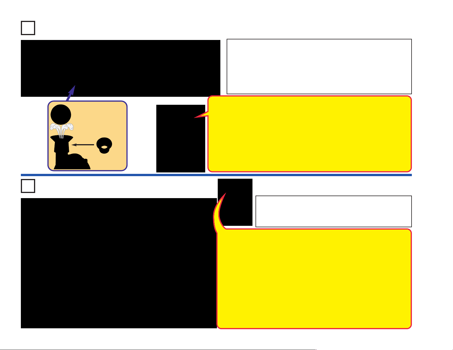
Project 120 Lots at Once
Build the circuit, but note that the air fountain (AF) is placed over the middle of
the 5-snap and 6-snap wires. Place the spout on top of the air fountain and
place the ball in it. Turn on the slide switch (S1).
Lots of stuff should be happening - the geared motor (GM) shaft spins, the ball
in the air fountain moves (it may rise into the air, or may just spin around),the
light motor (M7) spins and lights, and the LEDs (D8 & D10) are on.
You may place the merry-go-round base on the geared motor, but this is not necessary.
Place the spout
on top of the air
fountain and the
ball in the air flow.
Spout
Here five components (GM, AF, D10, M7, & D8) are all connected in parallel, so the
electric currents flowing through them can be different, and they are basically
independent of each other. Electricity flows out of the batteries, divides among the five
components, then recombines to flow through the switch and back into the batteries.
Each component gets what it needs from the batteries (unless the batteries are too weak
to supply enough), and all work properly. Also, if one breaks, the others keep working.
Note: this circuit connects the LEDs (D8 & D10) directly to the batteries without a resistor
or other device to limit the current. Normally this could damage an LED, but your Snap
®
Circuits
will not be damaged. They are connected directly to the batteries in this circuit to help
demonstrate how parallel circuits work.
LEDs have internal resistors added to protect them from incorrect wiring, and
Project 121 Electrical Circle
Rearrange the parts in the preceding circuit to make this one,
which has them connected in a loop. Turn on the slide switch (S1).
The LEDs (D8 & D10) light, but the geared motor (GM), air fountain
(AF), and light motor (M7) do nothing. Snappy knows why.
Compare this circuit to the preceding one. Here the same five components (GM, AF, D10,
M7, & D8) are all connected in series, so the electric current flowing through them must
be the same, and each affects the others. Electricity flows in a loop, from the batteries,
through each component, and then back into the batteries. Here the component with the
most resistance limits the flow of electricity. In this circuit the LEDs (D8 & D10) have the
most resistance due to their internal protection resistors (see above). The geared motor,
air fountain, and light motor are unable to function because the LED resistance limits the
current too much, though the electrical resistance of these devices is having an additional
small limiting effect on the current flow.
A second battery holder was added to this circuit because the combined turn-on voltage
of both LEDs (about 1.5V each) may be too high to make anything happen with just one
set of batteries (3V). You can try replacing one battery holder with a 3-snap wire and see
if the LEDs turn on.
Connecting parts in series makes the wiring less complex (especially important when the
components are far apart), makes it easier to protect sensitive devices, and can avoid
wasting energy (making batteries last longer).
-61-
Page 63

Project 122 Generator
Normally, the geared motor uses electricity to create
mechanical motion. This circuit uses the geared motor
in reverse, to use mechanical motion (from you spinning
the shaft) to create electricity (to light the LED).
Nearly all of the electricity used in our world is produced
at enormous generators driven by steam or water
pressure. Wires are used to efficiently transport this
energy to homes and businesses where it is used.
Motors convert the electricity back into mechanical form
to drive machinery and appliances.
Build the circuit shown, and mount the 2.55” gear
on the geared motor (GM). GENTLY spin the gear
with your hand in both directions while watching
the red/yellow bicolor LED (D10). The adjustable
resistor (RV2) controls the LED brightness, set it
towards the 2-snap wire for brightest. Do not try to
spin the gear with too much force or you may
break the geared motor.
Project 123
Leverage
Use the preceding circuit but replace the 2.55” with one
of the others. Be GENTLE when turning the gear or you
may break the geared motor (GM). Compare how much
easier or harder it is to turn and light the LED.
The larger the gear, the easier it is to turn the shaft and
light the LED. The size of the gear amplifies your power
to turn the shaft.
Compare this to using a wrench to tighten or loosen a
nut on a bolt. The wrench gives you leverage, increasing
your turning power.
Project 124
Generator Load
Build this circuit, and mount the 2.55” gear on
the geared motor (GM). GENTLY spin the gear
with your hand with the slide switch (S1) both
on and off. Compare how difficult it is to turn
whether the switch is on or off. You can also
try this with different gears. Do not try to spin
the gear with too much force or you may break
the geared motor.
You may notice air flowing in or out of the air
fountain (AF), but otherwise it won’t do
anything. It is not necessary or recommended
to place the spout or ball on the air fountain.
It should be more difficult to spin the gear when the switch is on,
because the air fountain is acting as a heavy electrical “load” or
burden on the geared motor. Powering the air fountain takes more
energy than powering nothing (such as when the switch is off) or
powering an LED (like in the preceding circuits).
-62-
Page 64

Project 125 Water Alarm
Build the circuit shown but initially leave the red & black jumper wires
outside the cup. Turn on the slide switch (S1); nothing happens. Place
the jumper wires into a cup of water and an alarm sounds!
Variants:
● Change the sound by using a 1-snap wire and a 2-snap wire to make
a connection across points A & B, or A & D, or B & C.
● Remove the NPN transistor (Q2) and instead connect the black
jumper wire at point B.
Don’t drink any water used here.
Water has higher electrical resistance than the
resistors in this set (RV2, and in the pivot stand), but
much less than air. The NPN transistor acts as an
amplifier, to help overcome water’s resistance.
You could use longer wires and lay them on your
basement floor, if your basement floods during a
storm, then this circuit will sound an alarm!
Project 126
Human Alarm
Use the preceding circuit but instead of putting the red
& black jumper wires in the water, touch the metal ends
of them with your fingers. You may have to hold them
tightly or wet your fingers to make this work.
Your body is mostly water, so it
also has more resistance than
the resistors in this set, but
much less than water.
-63-
Project 127
Draw an Alarm
Use the circuit from project 125, but omit the cup of water and leave
the loose ends of the jumpers unconnected for now. There is one
more part you need and you are going to draw it. Take a pencil (No.
2 lead is best but other types will also work). SHARPEN IT, and fill
in the shape below. You will get better results if you place a hard,
flat surface directly beneath this page while you are drawing. Press
hard (but don’t rip the paper), and fill in the shape several times
to be sure you have a thick, even layer of pencil lead.
Press the metal ends of the jumper wires on the shape and move
them around over the drawing. If you don’t hear any sound then
move the ends closer together and move over the drawing, add
another layer of pencil lead, or put a drop of water on the jumper
ends to get better contact. with your fingers.
The black core of
pencils is graphite, the
same material used in
the resistors in RV and
the pivot stand.
Page 65

Project 128
Project 129
Human & Water Light
Build the circuit and turn on the
switch (S1). Touch the metal in
the jumper wire snaps with your
fingers; the color LED (D8)
should light. If the LED is dim or
off, hold the metal more tightly
or wet your fingers.
Next, place the loose ends of
the jumper wires in a cup of
water, make sure the metal
parts aren’t touching each other.
The water should light the LED.
Don’t drink any water used
here.
Project 130 Trip-Wire Alarm
Conduction Detector
Use the preceding circuit but replace the color LED (D8) with
the red/yellow bicolor LED (D10, oriented in either direction).
Touch it with your fingers and put it in water as in the
preceding project. Next, touch the ends of the jumper wires
to different materials in your home, and see which ones light
the LED.
The color LED can be used instead of the red/yellow LED,
but the red/yellow LED isn’t changing colors, so may be
easier to compare if the LED only lights dimly.
Materials like metal conduct electricity
well and will light the LED. Plastics,
wood, and fabrics are poor conductors
and will not light the LED.
Build the circuit shown and turn on the slide switch (S1). Nothing
happens. Break the black jumper wire connection and an alarm sounds.
You could replace the black jumper wire with a longer wire and run it
across a doorway to signal an alarm when someone enters.
You can change the sound by using a 1-snap wire and a 2-snap wire to
make a connection across points A & B, or A & D, or B & C.
-64-
Page 66

Project 131 Current Limiters
Build the circuit, turn off the slide switch (S1) and set the switcher (S6)
to the middle position. The red/yellow bicolor LED (D10) is on, and you
can use the adjustable resistor (RV2) to vary its brightness a little.
The LED is not very bright because the circuit has two resistors limiting
the electric current through it (a 10,000 ohm resistor in the pivot stand
and RV2, which is adjustable between 200 ohms and 10,000 ohms).
Now turn on S1. The LED is brighter, and RV2 can vary the brightness
more than before.
S1 connects a much smaller 47 ohm resistor (also in the pivot stand) in
parallel with the 10,000 ohm resistor in the pivot stand. The smaller
resistor does not limit the current flow as much as the larger one, so
the LED is brighter.
Now set S6 to the right position. The LED is even brighter now, and RV2
no longer changes the brightness.
S6 bypasses RV2, allowing more current to flow, and making the LED brighter.
This circuit does not have an on/off switch, so disconnect it or remove
the batteries when you are finished.
-65-
Project 132
Current Limiters in Parallel
Build the circuit, turn off the slide switch (S1) and set the switcher (S6)
to the middle position. The red/yellow bicolor LED (D10) is on dimly.
The LED is not very bright because the only electrical path from the batteries
to the LED is through a 10,000 ohm resistor (the adjustable resistor, which
is used here as a fixed 10,000 resistor, and cannot be adjusted).
Now turn on S1. The LED is a little brighter.
S1 connects a 10,000 ohm resistor in the pivot stand in parallel with
RV2 (fixed at 10,000 ohms here). This gives two 10,000 ohm paths
from the batteries to the LED, instead of just one, so the current is higher
and the LED is brighter.
Now set S6 to the bottom position. The LED is much brighter now.
S6 connects a 47 ohm resistor in the pivot stand in parallel with the two
10,000 ohm resistors already in the circuit (one in the pivot stand and
one in RV2). This adds a much lower 47 ohm path between the batteries
and the LED, so a lot more current flows, and the LED is much brighter.
This circuit does not have an on/off switch, so disconnect it or remove
the batteries when you are finished.
Page 67

Project 133
Current Director
Turn on the slide switch (S1) and adjust the brightness of the LEDs (D8
& D10) with the adjustable resistor (RV2).
The adjustable resistor (RV2) has a total
of 10,000 ohms between the center and
the two sides, with the lever setting how
much is on each side.
Project 134
Reversible Current
Director
Turn on the slide switch (S1), set the switcher (S6) to the top or bottom
position, and adjust the brightness of the LEDs (D8 & D10) with the
adjustable resistor (RV2).
The red/yellow bicolor LED will light in both directions, but the color LED
(D8) only works in one direction.
-66-
Page 68

Project 135 Lazy Fan
Project 136
Set the adjustable resistor (RV2) to the top setting and
keep it there. Turn on the slide switch (S1). The fan on
the light motor (M7) spins briefly and stops. Now turn
off the slide switch, wait a little while, and then turn it
back on. The fan spins briefly again. Try this several
times.
It is as if the fan is lazy, and can only spin a short time
before it gets tired and has to stop and rest.
When you turn on the slide
switch, the fan spins while the
100mF capacitor (C4) charges
up, then stops. When you turn
off the slide switch, the capacitor
takes about 20 seconds to fully
discharge.
Project 137 Lazy Lights
Lazy Merry-
Go-Round
Use the preceding circuit but replace
the light motor (M7) with the geared
motor (GM, “+” on top). Install
cardboard figures in the merry-goround base and place the base on
the geared motor. The circuit works
the same way but spins the merrygo-round instead of the fan.
Project 138
Very Lazy
-67-
Set the adjustable resistor (RV2) to the top setting.
Turn on the slide switch (S1). The LEDs (D8 & D10)
light for a few moments. Now turn off the slide
switch, wait a little while, and then turn it back on.
The LEDs light briefly again. Try this several times.
It is as if the LEDs are lazy, and can only light for a
short time before they get tired and have to turn off
and rest.
Try this with different settings for RV2.
Lights
Use the preceding circuit but replace
the 100mF capacitor (C4) with the
much smaller 1mF capacitor (C7).
Now the LEDs only flash for a brief
moment, because C7 can’t store as
much electricity as C4 did.
Page 69

Project 139
Electricity You Can
Walk Away With
This circuit has two parts; build it as shown, but initially place the 100mF
capacitor (C4) across points A & B. Then pick up C4 and place it across
points C & D; the red/yellow bicolor LED (D10) flashes. Move C4
between points A/B & C/D several times.
In either location, C4 may be oriented in either direction, but its direction
determines the color of the LED flash.
You can replace the 100mF capacitor with the smaller 1mF capacitor
(C7), but the LED flash will be much dimmer.
Placing the capacitor across points A & B charges it
up, and placing it across points C & D discharges it
through the LED. Once charged, capacitors hold their
charge well - you can charge up the capacitor, walk
away with it for a while, then use it to light the LED.
Despite the “+” marking, connecting your capacitors
backwards across your batteries in this circuit will not
harm them.
Project 140
Electricity You Can
Walk Away With (II)
Modify the preceding circuit to match this one. It works the same way,
except the adjustable resistor (RV2) slows down the capacitor
discharge, making the LED dimmer but stay on longer. Try this at
different RV2 settings.
-68-
Page 70

Project 141
Project 142
Short Burst Machine Gun
Set the adjustable resistor (RV2)
to the bottom position. Turn on the
slide switch (S1). A machine gun
sounds for a second, then stops.
Turn off the slide switch, wait a
few seconds, then turn it back on
to hear the machine gun sound
again. Try this several times.
Project 143
Set the adjustable resistor (RV2) to the bottom position, and set the
switcher (S6) to the middle position. Turn on the slide switch (S1). The
color LED (D8) should light for a short while then go out. To reset the
timer for the light to stay on, set S6 to the right position for a moment,
then back to the middle position.
Moving the lever on RV2 up makes the LED dimmer but it stays on
longer.
Short-On Light
Short Burst
Sound &
Lights
Use the preceding circuit but
replace the 3-snap wire
between the alarm IC (U2) and
speaker (SP2) with the color
LED (D8, “+” on right) or the
red/yellow bicolor LED (D10, in
either orientation). The sound
will not be as loud now.
-69-
When you turn on the slide switch, the color
LED lights while the 100mF capacitor (C4)
charges up, then stops. Setting S6 to the right
position discharges C4.
Page 71

Project 144
Finger Touch Light
Set the adjustable resistor (RV2) to the top position, and turn on the
slide switch (S1). Turn on the red/yellow bicolor LED (D10) by touching
your fingers between points A & B. You may need to press hard or wet
your fingers to make the LED bright.
You can adjust the LED brightness using the lever on RV2, or replace
the red/yellow LED with the color LED (D8).
Electricity flowing through
your fingers is amplified by
the NPN transistor (Q2), and
is enough to turn on the LED.
If the contacts at points A & B
were interweaved as shown
below then you could make
this work with just one finger.
Project 145
Slow Off Light
Set the switcher (S6) to
the top position and turn
on the slide switch (S1).
The red/yellow bi-color
LED (D10) is on. Now set
S6 to the middle position
and wait; the LED goes
off after a little while. The
adjustable resistor (RV2)
can adjust how quickly
the light goes out.
Project 146
3-Position Switch
The switcher (S6), has 3 positions. In this circuit, one
position turns on the red/yellow LED (D10), one turns on
the color LED (D8), and one turns both LEDs off.
You can change the color on D10 by reversing its orientation.
-70-
Page 72

Project 147 One Way Electricity
Turn on the slide switch (S1). The red/yellow bicolor LED (D10) and light
motor (M7) are on. The adjustable resistor (RV2) sets the brightness
for D10.
When you turn off the slide switch, the lights on the light motor go off
immediately, but the red/yellow LED goes out slowly. RV2 sets how
quickly the red/yellow LED goes out.
The NPN transistor (Q2) is used here as a diode. A diode
only lets electricity flow in one direction.
When you turn off the switch, the red/yellow LED stays on
for a little while as the 100mF capacitor (C4) discharges
through it. The “diode” lets electricity flow from the batteries
to the capacitor, but blocks electricity from flowing from the
capacitor to the light motor. Without the diode the red/yellow
LED and light motor would turn off immediately after the
switch is turned off, because the low resistance of the light
motor would discharge the capacitor in an instant.
Project 148 Tilt Sound & Light
-71-
Build the circuit and turn on the slide switch (S1). A siren will sound or
a light will shine if the circuit is tilted or moved. Experiment to see which
tilt angles activate which effects.
If the circuit does not shut off when left alone, then tilt it slightly so it
turns off.
Variants: You can change the sound by removing the 1-snap and 2snap wires that are at point A, or by moving them to be across points A
& B. You can also replace the color LED (D8) with the red/yellow bicolor
LED (D10, oriented in either direction).
Page 73

Wrap glove
around spout
Project 149 Inflator
This project requires use of some household
materials. Build the circuit shown, then get an adult
to help you attach a latex glove (not included) or
similar to the spout for the air fountain using a rubber
band (one is included, or use one from your home),
as shown. Place the spout and glove on the air
fountain and turn on the slide switch (S1). Air should
be blowing into the glove, making it inflate. You may
be able to “wave” the glove by turning the slide switch
on and off.
Be sure your rubber band makes a good seal on the
spout, that allows air to flow into the glove without
much escaping. You may have to try it several times
to get it working properly.
Wrap rubber band
around glove
Place spout onto
Air Fountain (AF)
➧➧
You can try this with different materials around your
home. Do not use a balloon, because the air fountain
will not have enough air pressure to inflate it.
WARNING: Be careful not to use anything that could
get sucked into the air intake on the side of the air
fountain as this may damage the air fountain.
Project 150 Transistor
Build the circuit and turn on the slide switch (S1). Slowly move the lever
on the adjustable resistor (RV2) across its range while watching the
brightness of the red/yellow & color LEDs (D8 & D10).
Transistors, such as the NPN transistor (Q2),
can amplify electric currents. In this circuit, the
adjustable resistor controls a small current
going to the transistor through the red/yellow
LED. The transistor uses this small current to
control a larger current through the color LED.
At some RV2 settings, the control current is too
small to light the red/yellow LED, but the
transistor-amplified is large enough to light the
color LED.
-72-
Page 74

Project 151 Slow Light
Set the switcher (S6) to the middle position. Turn on the slide switch
(S1), nothing happens. Now set S6 to the top position; the red/yellow
bicolor LED (D10) takes a few seconds to turn on. Now set S6 back to
the middle position; the LED will very slowly get dim. The adjustable
resistor (RV2) controls the shut-off time.
You can reverse the orientation of the red/yellow bicolor LED, or replace
it with the color LED (D8, “+” on left).
The 100mF capacitor (C4) controls the red/yellow
LED through the NPN transistor (Q2). Setting S6
to the top position quickly charges up the
capacitor, and setting S6 back to the middle
position allows the capacitor to slowly discharge.
Capacitors can store electric charge and release
it when needed, so they are often used in timing
circuits like this.
Project 152 Wiggler
-73-
Place the
spout on top
of the air
fountain and
the ball in the
air flow.
Spout
Build the circuit as shown, place the spout on the air fountain (AF), place
the ball in the spout, set the lever on the adjustable resistor (RV2) to
the top, and turn on the slide switch (S1). Use the lever on the
adjustable resistor to adjust the brightness of the red/yellow bicolor LED
(D10) and make the ball move or “wiggle” around in the spout.
The ball will only move for a small part of RV2’s adjustment range. If you
replace the red/yellow LED with a 3-snap wire, the ball will move more.
This circuit uses the NPN transistor (Q2) and
adjustable resistor (RV2) to control the power to
the air fountain. A small electric current into the
transistor through RV2 and the LED (D10)
controls a larger current into the transistor through
the air fountain. RV2 cannot be used to control the
air fountain directly, because its high resistance
would prevent the air fountain from operating.
Page 75

Project 153 Blinker Beeper
Project 154
Build the circuit as shown and turn on the switch (S1).
The color LED (D8) will be blinking and you hear
beeping from the speaker (SP2). The adjustable
resistor (RV2) can adjust the sound and LED
brightness a little.
The color LED (D8) has a
microcircuit that changes the
light colors. As it does this, it
changes the current through
the circuit. The transistor (Q2)
amplifies the changing
current and uses it to control
the speaker (SP2).
Use the preceding circuit, but replace the
speaker (SP2) with the red/yellow bicolor
LED (D10, in either orientation). Now the
red/yellow LED will also be blinking.
Blinker
Blinker
Project 155 Blinker Control
Build the circuit as shown and turn on the switch (S1). The color LED
(D8) and red/yellow bicolor LED (D10) will both be blinking. The color
LED will be brighter than in the preceding circuit. The adjustable resistor
(RV2) can change the color LED brightness a little.
The red/yellow LED is controlled by the color LED using the transistor
(Q2). If you remove the color LED from the circuit then the red/yellow
LED will not light. Removing the red/yellow LED will not affect the color
LED.
Try swapping the locations of the color & red/yellow LEDs, reversing
the orientation of the red/yellow LED, or replacing the red/yellow LED
with the speaker (SP2).
-74-
Page 76

Project 156 Red Lights First
Set the switcher (S6) to the middle position and turn on the slide switch (S1). Set
the lever on the adjustable resistor (RV2) all the way to the left. The color LED
(D8) should be on, but may be mostly red. Slowly move the lever on RV2 to the
right until the LED is completely off. Notice that the red color stays on the longest.
Now set S6 to the right position and adjust RV2 again, watching the LED colors.
Blue and green color may also appear now, but may go dim before red does.
Now move S1 from the points marked C & D to the points marked A & B and set
S6 back to the middle position. Move RV2’s lever around again, watching the LED
colors and brightness. Set S6 to the right position again, and notice that the LED
now lights for a much larger part of RV2’s adjustment range.
The voltage needed to turn on an LED depends on the light color. Red
needs the least voltage, and blue needs the most. With S1 at points C
& D and S6 in the middle position, the voltage to the color LED is lowest,
and may barely be enough to turn on the red color. Setting S6 to the
right position bypasses the NPN transistor (Q2), and boosts the LED
voltage a little. Shifting S1 to points A & B increases the circuit voltage
from 3V to 6V, making the LED work for a greater part of RV2’s range.
-75-
Project 157
Red Just Before Yellow
Turn on the slide switch (S1). Set the switcher (S6) to both the left &
right positions at several settings on the adjustable resistor (RV2), and
compare the brightness of the red/yellow bicolor LED (D10). See if you
can notice a difference in the LED brightness between red and yellow,
especially when the LED is very dim.
Now move S1 from the points marked C & D to the points marked A &
B. Move RV2’s lever around again while changing S6 between left and
right, comparing the LED colors and brightness.
Yellow light is just slightly easier for the
red/yellow bicolor LED to produce than
red light. If you look closely at the LED
when it is dim, then you may notice that
red color is slightly brighter than yellow.
Page 77

Project 158
Loud Sirens
Build the circuit and turn on the slide switch (S1). You hear a siren.
Variants: You can change the sound by removing the 1-snap and 2snap wires that are at point A, or by moving them to be across points B
& C, or across points A & D.
Project 159
Adjustable Volume
Sirens
The preceding circuit may be too loud, so modify it to match this one,
which uses the adjustable resistor (RV2) as a volume control. Turn on
the slide switch (S1) and adjust the volume using RV2.
Variants: You can change the sound by removing the 1-snap and 2-snap
wires that are at point A, or by moving them to be across points B & C,
or across points A & D.
-76-
Page 78

Project 160 Capacitors in Series
Initially set the adjustable resistor (RV2) to the left, and the slide switch (S1) to
on. Set the switcher (S6) to the left position; the red/yellow bicolor LED (D10)
flashes brightly yellow as the 100mF capacitor (C4) charges up. Now set S6 to
the right position; the LED flashes brightly red as C4 discharges. Try switching
S6 to left and then to right several times.
Now set S1 to off; this connects the smaller 1mF capacitor (C7) in series with
the 100mF capacitor. Now repeat switching S6 to left and then to right several
times. The LED is much dimmer now, because the smaller capacitor can’t store
as much electricity, making the charging & discharging currents lower, which
makes the LED dimmer.
Next, repeat the above tests but try moving the lever on the adjustable resistor
around. Moving the lever on the adjustable resistor makes the capacitor
charge/discharge more slowly, making the LED dimmer but it stays on longer.
Think of capacitors as storage tanks for
electricity. If you place a small storage tank
in series with a big one, electricity flows into
both at the same time, but the small one fills
up quickly and stops the flow.
Project 161 Capacitors in Parallel
-77-
Initially set the adjustable resistor (RV2) to the left, and the slide switch (S1) to
off. Set the switcher (S6) to the left position; the red/yellow bicolor LED (D10)
flashes dimly yellow as the 1mF capacitor (C7) quickly charges up. Now set S6
to the right position; the LED flashes dimly red as C7 quickly discharges. Try
switching S6 to left and then to right several times.
Now set S1 to on; this connects the larger 100mF capacitor (C4) in parallel with
the 1mF capacitor. Now repeat switching S6 to left and then to right several
times. The LED is much brighter now, because the larger capacitor can store
more electricity, making the charging & discharging currents higher, which
makes the LED brighter.
Next, repeat the above tests but try moving the lever on the adjustable resistor
around. Moving the lever on the adjustable resistor makes the capacitor
charge/discharge more slowly, making the LED dimmer but it stays on longer.
Think of capacitors as storage tanks for
electricity. If you place a large storage tank
in parallel with a big one, electricity flows into
both at the same time, but keeps flowing
until both are full.
Page 79

Project 162
Place the
spout on top
of the air
fountain and
the ball in the
air flow.
Spout
Adjustable Light Motor
Build the circuit as shown. Place the spout and ball on the air fountain
(AF), and turn on the slide switch (S1). Use the lever on the adjustable
resistor (RV2) to adjust the brightness of the LEDs in the light motor
(M7) and red/yellow LED (D10), and to adjust the power to the air
fountain. For best effects, dim the room lights. The ball may spin on the
air fountain but may not rise into the air. New batteries are
recommended for this project.
Be sure to try this at very low light levels (where the motor is barely
spinning), as there some cool effects. If the fan on the light motor
doesn’t spin, try giving it a push to get started.
WARNING: Moving parts. Do not
!
touch the fan during operation.
Project 163
Adjustable
Low Speed Fan
Turn on the slide switch (S1) and adjust the fan speed for the light motor
(M7) using the lever on the adjustable resistor (RV2). Initially set RV2
to the top to get the motor started; if the fan does not start even at the
top RV2 setting then give it a push to get started. The fan will only spin
for a small part of RV2's adjustment range. The red/yellow bicolor LED
(D10) will usually light when the fan is not spinning.
New batteries are recommended for this project.
Note: Do not modify this circuit to use both battery holders as this may
reduce the life of your parts.
WARNING: Moving parts. Do not
!
touch the fan during operation.
-78-
Page 80

Project 164 Transistor Control
Insert some of the cardboard figures into the 3 slots on the
edge of the merry-go-round base. Build this circuit and mount
the merry-go-round base onto the shaft on the geared motor
(GM).
Set the lever on the adjustable resistor (RV2) to the top. Turn
on the slide switch (S1), and use the lever on the adjustable
resistor to set the brightness of the red/yellow bicolor LED
(D10) and the speed of the merry-go-round base.
The merry-go-round will only spin for a small portion of RV2’s
adjustment range. If it does not spin even at the top RV2
setting then give it a gentle push clockwise to get started.
Project 165 Reversible Motor
This circuit uses the NPN transistor
(Q2) and adjustable resistor (RV2) to
control the speed of the geared motor
(GM). A small electric current into the
transistor through RV2 and the LED
(D10) controls a larger current into the
transistor through the geared motor.
RV2 cannot be used to control the
geared motor directly, because its high
resistance would prevent the geared
motor from operating.
Project 166
-79-
Build the circuit, turn on the slide switch
(S1), and set the switcher (S6) to the left or
right to control the light motor (M7).
In the light motor (M7), the motor spins in
both directions but the LED light circuit only
works in one direction. LEDs are like little
one-way light bulbs.
Slow
Reversible
Motor
Use the preceding circuit, but
replace one of the battery holders
(B1) with a 3-snap wire. Now the
motor spins slower and the lights
are dimmer.
Page 81

Project 167 Orange Light
Turn on the slide switch (S1). Look at the red/yellow bicolor LED (D10)
in a dimly lit room. What color is the LED?
Variants: You can change the sound by removing the 1-snap and 2snap wires that are at point A, or by moving them to be across points B
& C, or across points A & D. The LED color may also appear to change
slightly.
The color on the LED is a blend of red & yellow, and
looks like orange.
The alarm IC (U2) is turning on and off rapidly to
create the siren sound pattern heard from the
speaker (SP2), and this also causes the 1mF
capacitor (C7) to be charged and discharged rapidly.
The LED is yellow when C7 is charging, and red
when C7 is discharging. The color is changing so fast
that it appears orange to your eyes.
Project 168
Light, Sound, & Flight?
WARNING: Moving parts. Do not
!
touch the fan during operation.
Assemble the airplane using the instructions
on page 5, install the light motor (M7) into the
front of it, build the circuit shown here, and
connect the red & black jumper wires to the
light motor (red to “+”). Spread out the jumper
wires and be sure they will not interfere with
the fan on the light motor.
Place the airplane on a smooth surface and
turn on the slide switch (S1). The fan on the
light motor spins and lights, a siren is heard,
and the airplane slowly moves around due to
vibration.
Variants: You can change the sound by
removing the 1-snap and 2-snap wires that are
at point A, or by moving them to be across
points B & C, or across points A & D.
-80-
Page 82

Notes
-81-
Page 83

OTHER SNAP CIRCUITS®PRODUCTS!
For a listing of local toy retailers who carry Snap Circuits®visit www.elenco.com or call us toll-free at 800-533-2441. For Snap Circuits
upgrade kits, accessories, additional parts, and more information about your parts visit www.snapcircuits.net.
Snap Circuits®Jr.
Model SC-100
Snap Circuits
Model SC-300
®
Snap Circuits®Pro
Model SC-500
Snap Circuits®Extreme
Model SC-750
®
Build over 100 projects
Including:
● Flying saucer
● Spin draw
● Sound activated switch
● Alarm circuit
Contains over 30 parts
Including:
● Photoresistor
● Motor
● Music IC
● Space War IC
Deluxe Snap Rover
Model SCROV-50
Features:
● Disc shooter
● Digital voice recorder
● Music sounds
● Goes forward &
backward
Contains over 60 projects
and over 50 parts
● Headlight
● Red & blue side lights
● Wireless remote control
● Left & right turning
control
Build over 300 projects
Including:
● AM radio
● Radio announcer
● Lie detector
● Burglar alarm
Contains over 60 parts
Including:
®
● Two transistors
● Microphone
Snap Circuits®Green
● Power amplifier IC
● Variable capacitor
Model SCG-125
Alternative Energy Kit
Build over 125 projects and have loads of fun learning
about environmentally-friendly energy and how the
electricity in your home works. Includes full-color manual
with over 100 pages and separate educational manual.
This educational manual will explain all the forms of
environmentally-friendly energy including: geothermal,
hydrogen fuel cells, wind, solar, tidal, hydro, and others.
Contains over 40 parts.
Build over 500 projects
Including:
● Digitally tuned FM radio
● Adjustable light control
● Digital voice recorder
● AC generator
Contains over 75 parts
Including:
● Recording IC
● FM module
● Transformer
● Analog meter
Snap Circuits®Light
Model SCL-175
Build over 175 projects
Including:
● Fiber Fun
● Dancing Lights
Contains over 55 parts
Including:
Strobe light, color organ, infrared detector, color
changing LED, fiber optic cable, and more!
● Follow the Music
Audio Infrared Detector
●
Build over 750 projects
Including:
● Strobe light
● Transistor AM radio
● Electromagnetism
● Rechargeable battery
Contains over 80 parts
Including:
● Solar cell
● Electromagnet
● Vibration switch
● Computer interface
Snap Circuits®Sound
Model SCS-185
Build over 185 projects
Including:
Sound Energy Demonstration
●
●
Keyboard w/ Voice Changer
Contains over 40 parts
Including:
Keyboard with optical theremin, echo integrated
circuit (IC), voice changer IC, audio jack, and more!
● Color Sound
● Optical Echo in Stereo
-82-
Page 84

SCM-165 MOTION Block Layout
Important: If any parts are missing or damaged, DO NOT RETURN TO RETAILER.
Call toll-free (800) 533-2441 or e-mail us at: help@elenco.com. Customer Service ● 150 Carpenter Ave.
Wheeling, IL 60090 U.S.A.
Blue Stand
Note: A complete parts list is on pages 2 and 3 in this manual.
Base Grid (11.0” x 7.7”) overlays many parts
 Loading...