

Page 1

Copyright © 2012, 2010 by Elenco®Electronics, Inc. All rights reserved. No part of this book shall be reproduced by 753104
any means; electronic, photocopying, or otherwise without written permission from the publisher.
REV-D Revised 2012
Project 317
Page 2
-1-
Table of Contents
Basic T roubleshooting 1
Parts List 2
MORE
About Your Snap Circuits®Parts 3, 4
MORE
Advanced T roub leshooting 4
MORE
DO’s and DON’Ts of Building Circuits 5
Project Listings 6, 7
Projects 306-511 8 - 61
Other Snap Circuits®Products 62
1. Most circuit problems are due to incorrect assembly.
Always double-check that your circuit exactly
matches the drawing for it.
2. Be sure that parts with positive/negative markings are
positioned as per the drawing.
3. Be sure that all connections are securely snapped.
4. Tr y replacing the batteries.
5. If the motor spins but does not balance the fan, check
the black plastic piece with three prongs on the motor
shaft. Be sure that it is at the top of the shaft.
Elenco
®
is not responsible for parts damaged due to
incorrect wiring.
Basic T roub leshooting
Note: If you suspect you have damaged parts, you can
follow the Advanced Troubleshooting procedure on page 4
to determine which ones need replacing.
Review of How To Use It (See page 3 of the Projects 1-101 manual for more details.)
The Snap Circuits®kit uses building blocks with snaps
to build the different electrical and electronic circuits in
the projects. These blocks are in different colors and
have numbers on them so that you can easily identify
them. The circuit you will build is shown in color and
with numbers, identifying the blocks that you will use
and snap together to form a circuit.
Next to each part in every circuit drawing is a small
number in black. This tells you which level the
component is placed at. Place all parts on level 1 first,
then all of the parts on level 2, then all of the parts on
level 3, etc.
A large clear plastic base grid is included with this kit
to help keep the circuit block together. The base has
rows labeled A-G and columns labeled 1-10.
Install two (2) “AA” batteries (not included) in the
battery holder (B1). The 2.5V and 6V bulbs come
packaged separate from their sockets. Install the 2.5V
bulb in the L1 lamp socket, and the 6V bulb in the L2
lamp socket.
Place the fan on the motor (M1) whenever that part is
used, unless the project you are building says not to
use it.
Some circuits use the red and black jumper wires to
make unusual connections. Just clip them to the metal
snaps or as indicated.
Note: While building the projects, be careful not to
accidentally make a direct connection across the
battery holder (a “short circuit”), as this may damage
and/or quickly drain the batteries.
WARNING: SHOCK HAZARD -
Never connect Snap Circuits®to
the electrical outlets in your home
in any way!
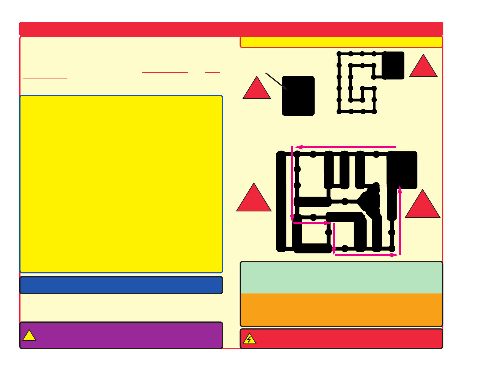
WARNING FOR ALL PROJECTS WITH A SYMBOL
Moving parts. Do not touch the motor or fan during operation. Do not lean
over the motor. Do not launch the fan at people, animals, or objects. Eye
protection is recommended.
!
!
WARNING: CHOKING HAZARD-
Small parts.
Not for children under 3 years.
!
Batteries:
• Use only 1.5V AA type, alkaline batteries
(not included).
• Insert batteries with correct polarity.
• Non-rechargeable batteries should not
be recharged. Rechargeable batteries
should only be charged under adult
supervision, and should not be
recharged while in the product.
• Do not mix alkaline, standard (carbonzinc), or rechargeable (nickel-cadmium)
batteries.
• Do not mix old and new batteries.
• Remove batteries when they are used up.
• Do not short circuit the battery terminals.
• Never throw batteries in a fire or attempt
to open its outer casing.
• Batteries are harmful if swallowed, so
keep away from small children.
• Do not connect batteries or battery
holders in parallel.
!
WARNING: Always check your wiring before
turning on a circuit. Never leave a circuit
unattended while the batteries are installed. Never
connect additional batteries or any other power
sources to your circuits. Discard any cracked or
broken parts.
Adult Supervision: Because children’s abilities
var
y so much, even with age groups, adults should
exercise discretion as to which experiments are
suitable and safe (the instructions should enable
supervising adults to establish the experiment’s
suitability for the child). Make sure your child reads
and follows all of the relevant instructions and
safety procedures, and keeps them at hand for
reference.
This product is intended for use by adults and
children who have attained sufficient maturity to
read and follow directions and warnings.
Never modify your parts, as doing so may disable
important safety features in them, and could put
your child at risk of injury.
!
Page 3
-2-
Qty. ID Name Symbol Par t # Qty. ID Name Symbol Par t #
r 3
2-Snap Wire 6SC02
r 1
Analog Meter 6SCM2
r 1
5-Snap Wire 6SC05
r 1
SCR 6SCQ3
r 1
Diode
1N4001
6SCD3
r 1
Relay 6SCS3
r 1
7-Segment
LED
Display
6SCD7
r 1
Transformer 6SCT1
r 1
FM Module 6SCFM
r 1
Recording
Integrated
Circuit
6SCU6
You may order additional / replacement parts at our website: www.snapcircuits.net
Q3
M2
FM
D3
5
2
S3
T1
U6
D7
Note: There are additional part lists in your other project manuals. Part designs are subject to change without notice.
Important: If any parts are missing or damaged, DO NOT RETURN TO RETAILER. Call toll-free (800) 533-2441 or e-mail us at:
help@elenco.com. Customer Ser vice • 150 Car penter Ave. • Wheeling, IL 60090 U.S.A.
Parts List (Colors and styles may vary) Symbols and Numbers
Page 4
-3-
(Part designs are subject to change without notice).
The FM module (FM) contains an integrated FM radio circuit.
Refer to the figure belo
w for the pinout description:
The meter (M2) is a very important indicating and measuring
device
. You’ll use it to measure the amount of current or voltage
depending on the circuit configuration. Notice the meter has a “+”
sign, indicating the positive terminal (+ power from the batteries).
The other snap is the negative terminal (– power return to
batteries). The meter has a switch to change between scales,
indicated as LOW and HIGH (or 10mA and 1A).
The recording IC module (U6) contains an integrated recording
circuit.
You can record a message up to five seconds long. There
are also three pre-recorded songs. Ref er to the figure below f or the
pinout descriptions:
The relay (S3) is an electronic switch with contacts that can be
closed or opened. It contains a coil that gener
ates a magnetic field
when current flows through it. The magnetic field attracts an iron
armature, which switches the contacts (see figure).
The transformer (T1) consists of two coil windings on one core.
One coil is called the Primar
y (input) and the other the Secondary
(output). The purpose of the transformer is to increase the amount
of AC voltage applied to the primary. This transformer is a step-up
transformer.
Diode (D3) - Think of a diode as a one-way valve that permits
current flow in the direction of the arro
w. The anode (arrow) is the
positive side, and the cathode (bar) is the negative. The diode
conducts or turns on when the voltage at the anode is 0.7V or
greater.
MORE
About Your New Snap Circuits®Parts (Note: There is additional information in your other project manuals).
(+)
OUT(–)
FM Module:
(+) - power from batteries
(–) - power return to batteries
T - tune up
R - reset
OUT - output connection
See project #307 for example of
proper connections.
(+)
OUT
(–)
Recording IC Module:
(+) - power from batteries
(–) - power return to batteries
RC - record
Play - play
OUT - output connection
Mic + - microphone input
Mic – - microphone input
See project #308 for example of
proper connections.
RCPlay
Mic –
Mic +
COM
Relay:
Coil - connection to coil
Coil - connection to coil
NC - normally closed contact
NO - normally open contact
COM - Common
See project #341 for example of
proper connections.
Coil
Coil
NO
NC
B
CTB
Transformer:
A - less windings side
A - less windings side
B - more windings side
B - more windings side
CT - center tap
See project #347 for example of
proper connections.
A
A
Anode
Diode:
Anode - (+)
Cathode - (–)
Cathode
(+)
(–)
Meter:
(+) - power from batteries
(–) - power return to batteries
Less Windings
More Windings
Our Student Guides give much more information about your parts, along with a complete lesson in basic electr onics. See www .snapcir cuits.net/learn.htm or page 62 for more inf ormation.
Page 5
Elenco®is not responsible for parts damaged due to incorrect wiring.
If you suspect you have damaged parts, you can follow this procedure to systematically
determine which ones need replacing:
1 - 20. Refer to project manuals 1 & 2 (projects #1-101, #102-305) for testing steps 1-20, then
continue belo
w.
21. FM Module (FM): Build project #307, you should hear FM radio stations.
22. Meter (M2): Build the mini-circuit shown here and set the meter switch
to LOW (or 10mA), the meter (M2) should deflect full scale
. Then, replace
the 10kΩ resistor (R4) with the 2.5V lamp (L1), and set the meter switch
to HIGH (or 1A). The meter should deflect to 1 or higher.
23. Recording IC (U6): Build project #308. Make an 8 second recording, then listen to the three
prerecorded songs
.
24. Relay (S3): Build project #341. The red LED (D1) should be on when the slide switch (S1) is
on, and the green LED (D2) should be on when the s
witch is off.
25. Transformer (T1): Build the mini-circuit shown here.
Pressing the press switch (S2) flashes the green LED
(D2). Connect the jumper wire to the CT point. Pressing
the press switch flashes the green LED.
26. Diode (D3): Build the mini-circuit shown here, the red LED (D1) should
light. Re
verse the direction of the diode, the LED should not light now.
27. SCR (Q3): Build the mini-circuit shown here. Turn on the slide
switch (S1) and the motor (M1) should not spin.
Press the press
switch (S2), the motor should start spinning. Now turn the slide
switch off and on, the motor should not spin.
28. 7-Segment Display (D7): Build project #337. All segments light, displaying the number 8.
-4-
SCR (Q3) - An SCR is a three-pin (anode, cathode
and gate) silicon-controlled rectifier diode. Like a
standard diode, it permits current flow in only one
direction. It will only conduct in the f orw ard direction
when triggered by a short pulse (or steady voltage
applied) between the gate and cathode terminals.
A
high current may damage this part, so the current
must be limited by other components in the
circuit.
The 7-segment display (D7) is found in many
devices today. It contains 7 LED’s that have been
combined into one case to make a convenient
device for displa ying n umbers and some letters. The
display is a common anode version. That means
that the positive leg of each LED is connected to a
common point which is the snap marked “+”. Each
LED has a negative leg that is connected to one
snap. To make it work you need to connect the “+”
snap to positive three volts. Then to make each
segment light up, connect the snaps of each LED to
ground. In the projects, a resistor is always
connected to the “+” snap to limit the current.
A high
current may damage this part, so the current must
be limited by other components in the circuit.
SCR:
A - Anode
K - Cathode
G - Gate
7-segment Display:
(+) - power from batteries
A - Segment A
B - Segment B
C - Segment C
D - Segment D
E - Segment E
F - Segment F
G - Segment G
DP - Decimal Point
See project #337 for example
of proper connections.
MORE
Advanced Troubleshooting (Adult super vision recommended)
MORE
About Y our Snap
Circuits
®
Parts (continued)
Page 6
-5-
MORE
DO’s and DON’Ts of Building Circuits
After building the circuits given in this booklet, you ma y wish to e xperiment on your own. Use
the projects in this booklet as a guide, as many important design concepts are introduced
throughout them. Every circuit will include a power source (the batteries), a resistance
(which might be a resistor, lamp, motor, integrated circuit, etc.), and wiring paths between
them and back. You must be careful not to create “short circuits” (very low-resistance paths
across the batteries
, see examples below) as this will damage components and/or quickly
drain your batteries. Only connect the IC’s using configurations given in the projects,
incorrectly doing so may damage them. Elenco®is not responsible for parts damaged
due to incorrect wiring.
Here are some important guidelines:
ALWAYS
USE EYE PROTECTION WHEN EXPERIMENTING ON YOUR OWN.
ALWAYS
include at least one component that will limit the current through a circuit, such
as the speaker, lamp, whistle chip, capacitors, IC’s (which must be connected
properly), motor, microphone, photoresistor, or fixed resistors.
ALWAYS
use the 7-segment display, LED’s , transistors, the high frequency IC, the SCR,
the antenna, and switches in conjunction with other components that will
limit the current through them. Failure to do so will create a shor t circuit
and/or damage those parts.
ALWAYS
connect the adjustable resistor so that if set to its 0 setting, the current will be
limited by other components in the circuit.
ALWAYS
connect position capacitors so that the “+” side gets the higher voltage.
ALWAYS
disconnect your batteries immediately and check your wiring if something
appears to be getting hot.
ALWAYS
check your wiring before turning on a circuit.
ALWAYS
connect IC’s, the FM module, and the SCR using configurations given in
the projects or as per the connection descriptions for the parts.
NEVER
try to use the high frequency IC as a transistor (the packages are similar, but the
parts are different).
NEVER
use the 2.5V lamp in a circuit with both battery holders unless you are sure that
the voltage across it will be limited.
NEVER
connect to an electrical outlet in your home in any way.
NEVER
leave a circuit unattended when it is turned on.
NEVER
touch the motor when it is spinning at high speed.
Note: If you have the more advanced Model SC-750, there are additional guidelines in your
other project manual.
For all of the projects given in this book, the parts may be arranged in diff erent ways without
changing the circuit. For example, the order of parts connected in series or in parallel does
not matter — what matters is how combinations of these sub-circuits are arranged together.
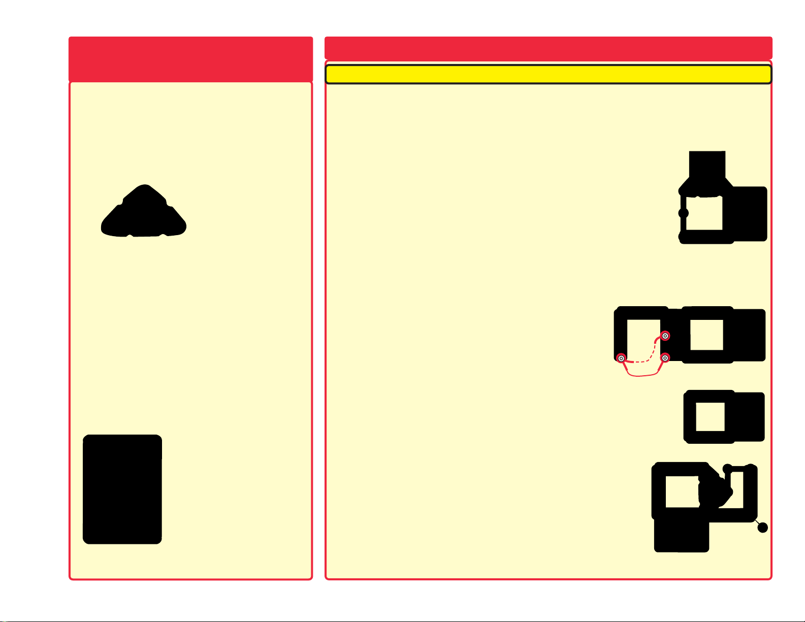
Examples of SHORT CIRCUITS - NEVER DO THESE!!!
You are encouraged to tell us about new circuits you create. If they are
unique, we will post them with your name and state on our website at
www.snapcircuits.net/kidkreations.htm. Send your suggestions to
Elenco
®
.
Elenco®provides a circuit designer so that you can make your own Snap
Circuits®drawings. This Microsoft®Word document can be downloaded
from www.snapcircuits.net/SnapDesigner.doc or through the
www.snapcircuits.net web site.
WARNING: SHOCK HAZARD - Nev
er connect Snap Circuits®to
the electrical outlets in your home in any way!
Placing a 3-snap wire directly
across the batteries is a
SHORT CIRCUIT.
This is also a
SHORT CIRCUIT.
When the slide switch (S1) is turned on, this large circuit has a SHORT
CIRCUIT path (as shown by the arrows). The short circuit prevents any
other portions of the circuit from ever working.
NEVER
DO!
Warning to Snap Rover owners: Do not connect your parts to the
Rover body except when using our approved circuits, the Rover
body has a higher voltage which could damage your parts.
!
!
NEVER
DO!
!
!
!
NEVER
DO!
NEVER
DO!
Page 7

Project # Description Page #
306 AM Radio 8
307 Adjustable Volume FM Radio 8
308 Playback & Record 9
309 Playing Music 9
310 Light-Controlled Music 9
311 Touch-Controlled Music 9
312 Power Playback & Record 10
313 Power Amplified Playing Music 10
314 Power Light-Controlled Music 10
315 Pow er Touch-Controlled Music 10
316 FM Radio 11
317 Mega Circuit 11
318 SCR 2.5V Bulb 12
319 SCR & Motor 12
320 Music Alarm 13
321 Light-Music Alarm 13
322 Light-Controlled SCR 13
323 3mA Meter 14
324 0-3V Meter 14
325 Function of adjustable resistor 15
326 Function of Photoresistor 15
327 Meter Deflect by Motor 16
328 SCR 6V Bulb 16
329 Principle of Segment LED 17
330 Display #1 17
331 Display #2 17
332 Display #3 17
333 Display #4 17
334 Display #5 18
335 Display #6 18
336 Display #7 18
337 Display #8 18
338 Display #9 18
339 Display #0 18
Project # Description Page #
340 Music Meter 18
341 LED & Relay 19
342 Manual 7 Second Timer 19
343 Half Wave Rectifier Circuit 20
344 Half Wave Rectifier Circuit (II) 20
345 LED vs. Diode 20
346 Current & Resistance 20
347 Telegraph 21
348 Mosquito Sound 21
349 Mosquito Sound (II) 21
350 Mosquito Sound (III) 21
351 Touch-Control Mosquito Sound 21
352 Bulb & Relay 22
353 Relay Buzzer 22
354 Transistor Timer 23
355 Light-Controlled Relay 23
356 Bulb Alert Relay 23
357 Adjustable Light Control 24
358 Meter Deflection 24
359 AC to DC Current 25
360 Current Meter 25
361 Buzzer, Relay, & Transformer 26
362 Buzzer & Relay 26
363 Display Capital Letter “F” 27
364 Display Capital Letter “H” 27
365 Display Capital Letter “P” 27
366 Display Capital Letter “S” 27
367 Display Capital Letter “U” 27
368 Display Capital Letter “C” 27
369 Display Capital Letter “E” 27
370 Display “.” 27
371 Display Letter “b” 28
372 Display Letter “c” 28
373 Display Letter “d” 28
Project # Description Page #
374 Display Letter “e” 28
375 Display Letter “h” 28
376 Recorded V oice Transmitter 28
377 Space War Alar m by SCR 29
378 Light Space War Alar m 29
379 Alarm by SCR 29
380 Light & Alarm IC 29
381 Delay Light 30
382 Delay Fan 30
383 Sound Activated Fan 30
384 Recording LED Indicator 31
385 Playback & Record with Meter 31
386 Alarm Light 32
387 Alarm Light (II) 32
388 Night Police Car 33
389 Night Machine Gun 33
390 Night Fire Engine 33
391 Night Ambulance 33
392 Daytime Light Police Car 34
393 Daytime Light Machine Gun 34
394 Daytime Light Fire Engine 34
395 Daytime Light Ambulance 34
396 Flashing 8 35
397 Flashing 8 with Sound 35
398 Musical Space War 35
399 Electronic Noisemaker 36
400 Electronic Noisemaker (II) 36
401 Bee 36
402 Bee (II) 36
403 Bee (III) 36
404 Oscillator Sound 37
405 Oscillator Sound (II) 37
406 Oscillator Sound (III) 37
407 Oscillator Sound (IV) 37
-6-
Project Listings
Page 8

-7-
Project # Description Page #
408 Oscillator Sound (V) 37
409 Transistor Tester 38
410 Adjustable Voltage Divider 38
411
Automatic Display Capital Letter “C”
39
412
Automatic Display Capital Letter “E”
39
413
Automatic Display Capital Letter “F”
39
414
Automatic Display Capital Letter “H”
39
415
Automatic Display Capital Letter “P”
39
416
Automatic Display Capital Letter “S”
39
417
Automatic Display Capital Letter “U”
39
418
Automatic Display Capital Letter “L”
39
419 Whistle Chip Sounds 40
420 Whistle Chip Sounds (II) 40
421 Whistle Chip Sounds (III) 40
422 Whistle Chip Sounds (IV) 40
423 Whistle Chip Sounds (V) 40
424 Whistle Chip Sounds (VI) 40
425 LED Music 41
426
Light-Controlled LED Time Delay
41
427
Touch-Controlled LED Time Delay
41
428 Alarm Recorder 42
429 Alarm Recorder (II) 42
430 Machine Gun Recorder 42
431 Time Delay 1-7 Seconds 43
432 Time Delay 43
433 Manual 7 Second Timer (II) 44
434 15 Second Alarm 44
435 Flashing “1 & 2” 45
436 Flashing “3 & 4” 45
437 Flashing “5 & 6” 45
438 Flashing “7 & 8” 45
439 Flashing “9 & 0” 45
440 Flashing “b & c” 46
441 Flashing “d & e” 46
442 Flashing “h & o” 46
Project # Description Page #
443 Flashing “A & J” 46
444
Alar
m Timer 46
445 Alarm Timer (II) 46
446 Alarm Timer (III) 46
447 Bird Sounds 47
448 Bird Sounds (II) 47
449 Bird Sounds (III) 47
450 Bird Sounds (IV) 47
451 Bird Sounds (V) 47
452 Touch-Control Bird Sound 47
453 Motor Sound Recording 48
454 Motor Sound Indicator 48
455 Relay & Buzzer 49
456 Relay & Speaker 49
457 Electronic Playground 49
458 Electronic Cat 50
459 Electronic Cat (II) 50
460 Electronic Cat (III) 50
461 Electronic Cat (IV) 50
462 Buzzer Cat 50
463 Buzzer Cat (II) 50
464 Buzzer Cat (III) 50
465 Lazy Cat 50
466 Meter Deflection (II) 51
467 Automatic Display #1 51
468 Automatic Display #2 51
469 Automatic Display #3 52
470 Automatic Display #4 52
471 Automatic Display #5 52
472 Automatic Display #6 52
473 Automatic Display #7 52
474 Automatic Display #8 52
475 Automatic Display #9 52
476 Automatic Display #0 52
477 Variable Oscillator 53
Project # Description Page #
478 Variable Oscillator (II) 53
479
V
ariable Oscillator (III) 53
480 Variable Oscillator (IV) 53
481 Photo V ariable Resistor 53
482 Variable Whistle Chip Oscillator 53
483 Slow Adjusting Tone 53
484 Slow Adjusting Tone (II) 53
485 Fixed-Current Path 54
486 Simple Illumination Meter 54
487 LED V oltage Drop 55
488 Open/Closed Door Indicator 55
489 Hand-Control Meter 56
490 Light-Control Meter 56
491 Electric-Control Meter 56
492 Sound-Control Meter 56
493 Fixed-Voltage Divider 57
494 Resistor Measurement 57
495 Automatic Display Letter “b” 58
496 Automatic Display Letter “c” 58
497 Automatic Display Letter “d” 58
498 Automatic Display Letter “e” 58
499 Automatic Display Letter “h” 58
500 Automatic Display Letter “o” 58
501 Hand-Control Display 1 & 4 59
502 Hand-Control Display 1 & 0 59
503 Hand-Control Display 1 & 7 59
504 Hand-Control Display 1 & 8 59
505 Hand-Control Display 1 & 9 59
506
Monitor Capacitor Charging & Discharging
60
507 Hand-Control Space Meter 60
508 Rhythm Swinging Meter 61
509
Police Car Sound with Whistle Chip
61
510
Fire Engine Sound with Whistle Chip
61
511
Ambulance Sound with Whistle Chip
61
Project Listings
Page 9

-8-
Project #306
OBJECTIVE: To build a one-IC AM radio.
Turn on the slide switch (S1) and adjust the variable capacitor (CV) for
a radio station. Make sure you set the variable resistor (RV) control to
the left for louder sound.
AM Radio
Project #307
OBJECTIVE: To build a working FM radio with adjustable
volume.
Turn on the slide switch (S1) and press the R button. Now press the
T button and FM module (FM) scans for a radio station. When a
station is found, it locks on to it and you hear it on the speaker (SP).
Adjust the volume using the adjustable resistor (RV). The resistor
controls the amount of signal into the power amplifier IC (U4). Press
the T button again for the next radio station. The module will scan up
to 108MHz, the end of the FM band, and stop. You must then press
reset (R) to start at 88MHz again.
Adjustable Volume
FM Radio
Page 10
-9-
Project #308
Build the circuit shown. Turn on the slide switch (S1), you hear a beep
signaling that you may begin recording. Talk into the microphone (X1)
up to 5 seconds, and then turn off the slide switch (it also beeps after
the 5 seconds expires).
Press the press switch (S2) for playback. It plays the recording you
made followed by one of three songs. If you press the press switch
before the song is over, music will stop. You may press the press
switch several times to play all three songs. The lamp (L2) is used to
limit current and will not light.
Playback & Record
OBJECTIVE: To demonstrate the capabilities of the recording
integrated circuit.
OBJECTIVE: To play the three built-in
songs on the recording IC.
Use the circuit in project #308. Turn on the
slide switch (S1), then press the press switch
(S2) to start the first song. When the music
stops, press the press switch again to hear the
second song. When the second song stops,
press the press switch again, the third song
plays.
Playing Music
Project #309
OBJECTIVE: To build a circuit that uses
light to control the recording IC.
Light-
Controlled
Music
Project #310
OBJECTIVE: To build a circuit that lets you
control the recording IC with your fingers.
Touch-
Controlled
Music
Project #311
Use the circuit in project #308. Replace the
press switch (S2) with the photoresistor (RP),
then turn on the slide switch (S1). Turn the
music on and off by waving your hand over
photoresistor.
Use the circuit in project #308. Place a single
snap on base grid point F1. Replace the
press switch (S2) with the PNP transistor (Q1,
with the arrow on point E2) and then turn on
the slide switch (S1). Turn the music on and
off by touching points F1 & G2 at the same
time. You may need to wet your fingers.
Visit www.snapcircuits.net or page 62 to learn about Snap Circuits®upgrade kits, which have more parts and circuits.
Page 11
-10-
Project #312
Connecting the power amplifier IC (U4) to the output of the recording
IC (U6), you can make much louder music than project #308.
Turn on the switch (S1), you hear a beep signaling that you may begin
recording. Talk into the microphone up to 5 seconds, and then tur n
open the switch (it also beeps after the 5 seconds expires).
Press the press switch (S2) for playback. It plays the recording you
made followed by one of three songs. If you press switch (S2) before
the song is over, music will stop. You may press the press switch
several times to play all three songs.
Power Playback &
Record
OBJECTIVE: To build a circuit that amplifies the recording IC.
OBJECTIVE: To amplify the output of the
recording IC.
Use the circuit in project #312. Turn on the
switch (S1), then press the press switch (S2)
to start the first song. When the music stops,
press the press switch again to hear the
second song. When the second song stops,
press the press switch again, the third song
plays.
Power
Amplified
Playing Music
Project #313
OBJECTIVE: Show variations of project
#312.
Power Light-
Controlled
Music
Project #314
OBJECTIVE: Show variations of project
#312.
Power Touch-
Controlled
Music
Project #315
Use the circuit in project #312. Replace the
press switch (S2) with the photoresistor (RP),
then turn on the switch (S1). Tur n the music
on and off by waving your hand over
photoresistor.
Use the circuit in project #312. Place a single
snap on base grid point F1. Replace the
press switch (S2) with the PNP transistor (Q1,
with the arrow on point E2) and then turn on
the slide switch (S1). Turn the music on and
off by touching points F1 & G2 at the same
time. You may need to wet your fingers.
Page 12

-11-
Project #316
OBJECTIVE: To build a working FM radio.
The FM module (FM) contains a scan (T) and a reset (R) button. The
R button resets the frequency to 88MHz. This is the beginning of the
FM range. Press the T button, the module scans for the next available
radio station.
Turn on the slide switch (S1) and press the R button. Now press the
T button and the FM module scans for an available radio station.
When a station is found, it locks on to it and y ou hear it on the speaker.
Press the T button again for the next radio station. The module will
scan up to 108MHz, the end of the FM band, and stop. You must then
press the reset (R) button to start at 88MHz again.
FM Radio
Project #317
OBJECTIVE: To build a complex circuit.
Note that there is a 3-snap wire between RV and U4, partially hidden
under R4.
This is an example of using many parts to create an unusual circuit.
Set the meter (M2) to the LOW (or 10mA) scale. Turn on the slide
switch (S1). As the circuit oscillates, the 7-segment display (D7)
flashes the number 5 and the LED’s (D1 & D2) flash as well. The
meter deflects back and forth and the speaker (SP) sounds a low tone
at the same rate. The frequency of the circuit can be changed by
adjusting the adjustable resistor (RV).
Next, place the 100Ω resistor (R1) directly over the diode (D3) using a
1-snap. See how this changes the circuit performance.
Mega Circuit
Page 13
-12-
Project #318
OBJECTIVE: To learn the principle of an SCR.
This circuit demonstrates the principle of the SCR (Q3). The SCR can
be thought of as an electronic switch with three leads: anode, cathode ,
and gate. Like a standard diode, it permits current flow in only one
direction. It will only conduct in the forward direction when triggered
by a short pulse or steady voltage applied between the gate and
cathode terminals. One set of batteries powers the lamp, the other is
used to trigger the SCR.
Turn on the slide switch (S1) and the bulb (L1) should not light. Now
press the press switch (S2); the SCR tur ns on and lights the bulb. To
turn off the bulb you must turn off the slide switch (S1).
SCR 2.5V Bulb
Project #319
OBJECTIVE: To activate a motor using an SCR.
SCR & Motor
Place the fan onto the motor (M1). In this circuit, the gate is connected
to the battery (B1) through the 1KΩ resistor (R2). When the slide
switch (S1) is turned on, it triggers the gate, the SCR (Q3) conducts,
and the motor spins. The motor continues to spin until the switch is
turned off.
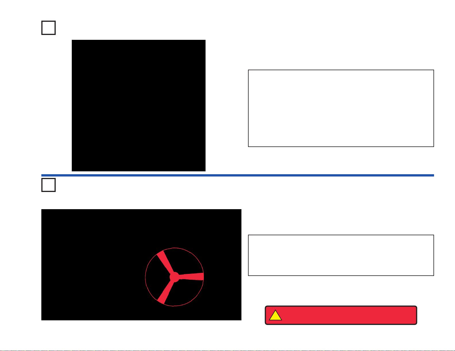
!
WARNING: Moving parts. Do not touch the fan or
motor during operation. Do not lean o ver the motor.
To learn more about how circuits work, visit www.snapcircuits.net or page 62 to find out about our Student Guides.
Page 14
-13-
Project #320
OBJECTIVE: To build a music alarm.
The alarm circuit activates when you remove the jumper wire from
points A & B. The jumper wire shorts the SCR’s (Q3) gate to ground
and the SCR does not conduct. Removing the jumper wire places a
voltage on the gate and the SCR conducts. This connects the battery
to the music IC (U1) and music is played.
Construct the circuit and you should hear no music. Now remove the
jumper wire and the music starts playing.
Music Alarm
Project #321
OBJECTIVE: To build a light-music alarm.
Light-Music Alarm
Use the circuit in project #320. Replace the resistor R3 with the
photoresistor (RP) and remove the jumper wire. Cover the
photoresistor with your hand. Now slowly remove your hand. When
enough light hits the resistor, the music plays.
Project #322
OBJECTIVE: To build a circuit that activates a bulb and motor
with the amount of light present.
Cover the photoresistor (RP) with your finger. Turn on the switch (S1),
and only the LED (D1) lights. The relay (S3) connects the motor (M1)
and the bulb (L2) to the batteries, but the motor and bulb are
powerless until a voltage is applied to the SCR's gate.
Remove your finger, as light hits the photoresistor, its resistance
decreases and a voltage appears on the gate of the SCR (Q3). The
SCR conducts and the motor and bulb work now.
Light-controlled SCR
!
WARNING: Moving parts. Do not touch the fan or
motor during operation. Do not lean o ver the motor.
Page 15

-14-
Project #323
OBJECTIVE: To build a 3mA meter circuit.
3mA Meter
Project #324
OBJECTIVE: To build a voltmeter.
0-3V Voltmeter
Build this 0-3V voltmeter circuit. Set the meter (M2) to the LOW (or
10mA) setting. Using new batteries, place the battery holder between
points A & B. Adjust the adjustable resistor (RV) so the meter deflects
full scale.
Now you can check y our other “AA” batteries b y inserting them into the
battery holder.
Set the meter (M2) to the LOW (or 10mA) scale. Inside the meter,
there is a fixed magnet and a mov eable coil around it. As current flows
through the coil, it creates a magnetic field. The interaction of the two
magnetic fields cause the coil (connected to the pointer) to move
(deflect). By itself, the meter can measure 300μA. To increase its
range, resistors are connected in parallel or in series to the meter.
Build the circuit shown. Placing the 100Ω resistor (R1) in parallel with
the meter increases the range by 10 times to 3mA. More current flows
through the resistor than the meter. The lower the resistor value, the
wider the range of the meter.
Page 16

-15-
Project #325
OBJECTIVE: To understand the function of the adjustable resistor.
An adjustable resistor is a normal resistor with an additional arm contact.
The arm moves along the resistive material and taps off the desired
resistance.
The slider on the adjustable resistor moves the arm contact and sets the
resistance between the bottom (point C1) pin and the center pin (point
B2). The remaining resistance is between the center and top pin. For
example, when the slider is all the way down, there is minimal resistance
between the bottom and center pins (usually 0Ω) and maximum
resistance between the center and top pins. The resistance between the
top (point A1) and bottom (point A3) pins will always be the total
resistance, (50kΩ for your part).
Set the meter (M2) to the LOW (or 10mA) scale. Adjust the adjustable
resistor (RV) for maximum resistance by setting the slider to the top. The
meter only deflects part of the way. As you move the slider down,
decreasing the resistance, the meter deflects more.
Function of
Adjustable Resistor
Project #326
OBJECTIVE: To understand the function of the photoresistor.
Build the circuit shown. Set the meter (M2) to the LOW (or 10mA)
scale. The photoresistor (RP) is a light-sensitive resistor. Its value
changes from nearly infinite in total darkness to about 1,000Ω when a
bright light shines on it.
The meter reading changes as the resistance changes in the circuit.
When the lights are on, the meter points to a higher number on the
scale. When the lights are OFF, the pointer will point to a lower number
on the scale. This means that the resistance of the photoresistor is
changing according to the amount of light in the room.
Function of
photoresistor
Visit www.snapcircuits.net or page 62 to learn about more Snap Circuits®products to add to your collection.
Page 17

-16-
Project #328
OBJECTIVE: To learn the principle of an SCR.
In this circuit, the 6-volt bulb (L2) will not light until the SCR (Q3) is
triggered. T urn on the slide switch (S1) and the b ulb will not light. Now
press the press switch (S2) to light the bulb. The bulb will stay lit until
the slide switch is turned off. To protect the SCR, a current limiting 1kΩ
resistor (R2) is placed in series with the gate.
SCR 6V Bulb
Project #327
OBJECTIVE: To change the direction of current flow using a
motor.
Set the meter (M2) to the LOW (or 10mA) setting. A motor generates
a current when it rotates. The rotation of the motor determines the
direction current flows. Quickly spin the motor (M1) clockwise with
your hand; the meter deflects to the right. Now spin the motor
counterclockwise, and the meter deflects to the left.
Meter Deflect
by Motor
Page 18
-17-
Project #329
OBJECTIVE: To demonstrate how a seven segment LED works.
The display (D7) is made up of seven segments. Each segment
contains an LED connected to an input snap. When the snap is
connected to the negative of the battery the segment lights. For
example, connect the circuit as shown and the letter “L” lights.
Principle of
Segment LED
Project #330
OBJECTIVE: To configure the seven
segment to display the number 1.
Connect B & C to the negative of the
battery.
Display #1
OBJECTIVE: To configure the seven
segment to display the number 2.
Connect A, B, G, E, & D to the negative
of the battery.
Display #2
OBJECTIVE: To configure the seven
segment to display the number 3.
Connect A, B, G, C, & D to the negativ e
of the battery.
Display #3
OBJECTIVE: To configure the seven
segment to display the number 4.
Connect B, C, F, & G to the negative of
the battery.
Display #4
Project #331
Project #332 Project #333
Page 19
-18-
Project #334
OBJECTIVE: To configure the seven
segment to display the number 5.
Connect A, F, G, C, & D to the negative of the
battery.
Display #5
Project #335
OBJECTIVE: To configure the seven
segment to display the number 6.
Connect A, C, D, E, F, & G to the negative of
the battery.
Display #6
Project #336
OBJECTIVE: To configure the seven
segment to display the number 7.
Connect A, B, & C to the negative of the
battery.
Display #7
Project #337
OBJECTIVE: To configure the seven
segment to display the number 8.
Connect A, B, C, D, E, F & G to the negative
of the battery.
Display #8
Project #338
OBJECTIVE: To configure the seven
segment to display the number 9.
Connect A, B, C, D, F, & G to the negative of
the battery.
Display #9
Project #339
OBJECTIVE: To configure the seven
segment to display the number 0.
Connect A, B, C, D, E, & F to the negative of
the battery.
Display #0
Project #340
OBJECTIVE: See and hear the output of the music IC.
Set the meter (M2) to the LOW (or 10mA) setting. In this circuit, the
output of the music IC (U1) is applied to the less windings side of the
transformer (T1), which lights the LED (D1) and deflects the meter.
Place the adjustable resistor (RV) to the bottom position and turn on
the switch (S1). Adjust the adjustable resistor upwards. This
increases the voltage across the LED and meter. The LED brightens
and the meter deflects more towards 10. Place the speaker (SP)
across points A & B and use a jumper wire to complete the connection.
Now you can hear and see the output of the music IC.
Music Meter
Visit www.snapcircuits.net or page 62 to learn about Snap Circuits®upgrade kits, which have more parts and circuits.
Page 20

-19-
Project #341
OBJECTIVE: Turn on and off LED’s using a relay.
A relay is an electronic switch with contacts that are opened or closed
using voltage. It contains a coil that generates a magnetic field when
a current flows through it. The magnetic field attracts an iron armature
which switches the contacts. Contact #2 is normally closed,
connecting the green LED (D2) and the resistor across the batteries.
With the slide slide switch (S1) turned off, the green LED should light.
Now turn on the switch, contact #1 on the relay (S3) will switch to
contact #3, lighting the red LED (D1).
LED & Relay
Project #342
OBJECTIVE: To build a manual timer using a relay.
The transistor (Q2) acts as a switch, connecting the relay (S3) to the
batteries. As long as there is positive voltage on the transistor’s base,
the bulb (L2) will light.
Turn on the slide switch (S1) and hold down the press switch (S2). The
transistor turns on, capacitor C5 charges up, and the bulb lights.
When the press switch is released, the capacitor discharges through
the base, keeping the transistor on. The transistor will turn off when
the capacitor is almost discharged, about 7 seconds. The relay
contacts will switch and the bulb will turn off.
Change the value of the capacitor and see what happens.
Manual
7 Second Timer
Page 21
-20-
Project #343
OBJECTIVE: To build a half wave rectifier circuit.
A rectifier changes an AC voltage into a DC voltage. A diode (D1) is
used because it allows current to flow in only one direction, for one
polarity of applied voltage. As the contacts open and close, it
generates an AC voltage across the transformer (T1). We can
measure the DC current from the transformer’s output using a resistor
(R2), a diode (D1), and a meter (M2). Set the meter to the LOW (or
10mA) scale. Turn on the slide switch (S1), the LED lights as the meter
points past the 5 scale.
Half Wave
Rectifier Circuit
OBJECTIVE: Measure the voltage using the
center-tap.
Use the circuit in project #343. Now see what
happens if you connect to the center-tap on
the side with more windings. Place the meter
(M2) across points A & B, then turn on the
switch (S1). The needle should deflect less,
about half as much as project #343. As you
use less windings, the output decreases.
Half Wave
Rectifier
Circuit (II)
Project #344
OBJECTIVE: To see the voltage difference
between an LED and diode.
Use the circuit in project #343. Replace the
LED (D1) with the diode (D3) and turn on the
switch (S1). The needle deflects higher,
because the voltage drop across the diode is
less than the voltage drop across the LED.
LED vs. Diode
Project #345
OBJECTIVE: See how resistance affects
current.
Change the 1kΩ (R2) resistor to a 5.1kΩ (R3)
and turn on the switch (S1). You will see that
increasing the resistance decreases the
current through the meter (M2).
Current &
Resistance
Project #346
Page 22

-21-
Project #347
OBJECTIVE: Making telegraph sounds.
Press the press switch (S2) down. The circuit oscillates and the AC
voltage generated from the transformer (T1) drives the speaker (SP).
To make a telegraph sound, depress the switch for long and short
periods.
Telegraph
OBJECTIVE: Show variations of project
#347.
Use the circuit in project #347. Connect the
whistle chip (WC) across points B & E.
Mosquito
Sound (II)
Project #349
OBJECTIVE: Show variations of project
#347.
Mosquito
Sound (III)
Project #350
OBJECTIVE: To use the photoresistor to
adjust the oscillator sound.
Touch-Control
Mosquito Sound
Project #351
OBJECTIVE: Use the whistle chip to make a mosquito sound.
Use the circuit in project #347. Remove the speaker (SP). Connect
the whistle chip (WC) across points C & D to make a mosquito sound.
Mosquito Sound
Project #348
Use the circuit in project #347. Connect the
whistle chip (WC) across points E & D (place
it beneath capacitor (C2) or use the jumper
wires).
Use the circuit in project #347. Replace the
100kΩ resistor (R5) with the photoresistor
(RP). Wave your hand over the resistor and
the sound changes.
To learn more about how circuits work, visit www.snapcircuits.net or page 62 to find out about our Student Guides.
Page 23

-22-
Project #353
OBJECTIVE: To make a relay buzzer.
When you turn on the switch (S1), you should hear a buzzing sound
from the relay (S3). The sound is caused by the relay’s contacts
opening and closing at a fast rate.
Relay Buzzer
Project #352
OBJECTIVE: Light a bulb using a relay.
Bulb & Relay
Turn off the slide switch (S1). If you press switch (S2), the lamp (L2)
will not light. T urn on the slide switch and press the press s witch again;
the lamp lights and stays on until the slide switch is turned off. This
circuit remembers that the press switch was pressed. Turn the slide
switch off and back on again. The lamp will be off until the press switch
is pressed, then the lamp will stay on. Computers use memory circuits
to remember states like on and off.
Page 24

Project #355
OBJECTIVE: To use a photoresistor to control a relay.
Under normal light, the resistance of the photoresistor (RP) is low, allowing a voltage at
the base of the transistor (Q2). This tur ns the transistor on, connecting the relay (S3)
across the batteries, and the bulb (L2) lights. If the light decreases, the resistance
increases and the voltage to Q2 drops. If the voltage at Q2 decreases enough, the
transistor turns off.
Tur n on the slide switch (S1) and the bulb lights. Now as you block the light from the
photoresistor, the bulb turns off.
Light-controlled Relay
OBJECTIVE: Make a warning system that lights the bulb.
Replace the photoresistor (RP) with a 10kΩ resistor (R4). Connect the wire to
points A & B. As long as the wire is connected, the transistor (Q2) is off and
the relay (S3) and bulb (L2) are not powered. Disconnect the wire. The relay
contacts will switch and the bulb will light.
Bulb Alert Relay
Project #356
-23-
Project #354
OBJECTIVE: To build a manual timer using a transistor in
place of the relay.
This circuit is similar to project #342 except now two transistors are
used. Tur n on the slide switch (S1) and hold down the press switch
(S2). The transistors (Q1 & Q2) turn on, the capacitor (C3) charges
up, and the bulb (L2) lights. When the press switch (S2) is released,
the capacitor discharges through the base, keeping the transistors on.
The transistors will turn off when the capacitor is almost discharged
(about 1 minute). The relay (S3) contacts will switch and the bulb will
turn off.
Transistor Timer
Page 25

-24-
Project #357
OBJECTIVE: Build an adjustable light-controlled relay.
You can set the amount of light it takes to keep the bulb (L2) on by
adjusting the adjustable resistor (RV). Set the adjustable resistor to
the top position and turn on the switch. The bulb lights. Cover the
photoresistor (RP) and the bulb turns off. Set the adjustable resistor
to different positions and then cover the photoresistor. Note that only
the top half of the adjustable resistor affects the circuit. If you position
it below the middle, the bulb stays off.
Adjustable Light
Control
Project #358
OBJECTIVE: To demonstrate the properties of a transformer.
Set the meter (M2) to the LOW (or 10mA) scale. Pressing the press
switch (S2) generates a current on the left side of the transf ormer (T1).
The current lights the LED’s (D1 & D2) and deflects the meter. There
are two current paths as shown by the arrows. Placing the meter in
both current paths always measures each current. The top current is
produced when the press switch is pressed and the bottom current is
produced when the press switch is released.
Meter Deflection
Visit www.snapcircuits.net or page 62 to learn about more Snap Circuits®products to add to your collection.
Page 26
Project #360
OBJECTIVE: To measure the current through a transformer.
Set the meter (M2) to the LOW (or 10mA) setting. By placing the
meter, diode (D3) and current limiting resistor (R4) on the transfor mer
(T1), you can measure the current. Turn on the slide slide switch (S1)
and the motor (M1) starts spinning. The current on the right side of the
transformer creates a current on the left side using magnetism.
Current Meter
-25-
Project #359
OBJECTIVE: To convert an AC current to DC using an LED.
Set the meter (M2) to the LOW (or 10mA) scale. Pressing and
releasing the press switch (S2) continuously generates an AC
(changing) current. The LED (D1) is used to convert the AC
(changing) current to DC (unchanging) current because it only allows
the current to flow in one direction. The LED should light as the meter
deflects to the right only. Without the LED, the meter would deflect in
both directions.
AC to DC Current
!
WARNING: Moving parts. Do not touch the fan or
motor during operation. Do not lean o ver the motor.
Page 27

-26-
Project #361
OBJECTIVE:
To use a transformer for a louder buzzer.
Turn on the switch (S1). The speaker (SP) generates a buzzer sound.
As in project #353, the relay (S3) is rapidly switched on and off. This
causes an AC voltage on the left side of the transfor mer (T1). The
voltage is stepped-down and applied to the speaker, generating the
sound.
To make the sound a little louder, replace the 0.1μF capacitor (C2) with
a 3-snap wire.
Buzzer, Relay, &
Transformer
Project #362
OBJECTIVE: Make a relay buzzer with speaker.
A speaker (SP) and capacitor (C2) are placed across the coil of the
relay (S3). When the slide switch (S1) is turned on, the relay’s
contacts open and close as in project #353. As the capacitor (C2)
charges and discharges, the speaker generates a buzzing sound.
Buzzer & Relay
Page 28
-27-
Project #363
OBJECTIVE: To configure the seven
segment to display the capital letter “F”.
Connect A, E, F, & G to the negative of
the battery.
Display Capital
Letter “F”
OBJECTIVE: To configure the seven
segment to display the capital letter “H”.
Connect B, C, E, F, & G to the negative
of the battery.
Display Capital
Letter “H”
OBJECTIVE: To configure the seven
segment to display the capital letter “P”.
Connect A, B, E, F, & G to the negative
of the battery.
Display Capital
Letter “P”
OBJECTIVE: To configure the seven
segment to display the capital letter “S”.
Connect A, F, G, C, & D to the negative
of the battery.
Display Capital
Letter “S”
Project #364
Project #365 Project #366
Project #367
OBJECTIVE: To configure the
seven segment to display the capital
letter “U”.
Connect B, C, D, E, & F to the
negative of the battery.
Display Capital
Letter “U”
Project #370
OBJECTIVE: To configure the
seven segment to display the
decimal (DP).
Connect DP to the negative of the
battery.
Display “.”
Project #369
OBJECTIVE: To configure the
seven segment to display the
capital letter “E”.
Connect A, D, E, F, & G to the
negative of the battery.
Display Capital
Letter “E”
Project #368
OBJECTIVE: To configure the
seven segment to display the
capital letter “C”.
Connect A, D, E, & F to the
negative of the battery.
Display Capital
Letter “C”
Visit www.snapcircuits.net or page 62 to learn about Snap Circuits®upgrade kits, which have more parts and circuits.
Page 29
-28-
Project #376
OBJECTIVE: To hear your voice on the radio.
You need an AM radio for this project. Build the circuit sho wn and place
it next to your AM radio. Tune the radio frequency to where no other
station is transmitting. Push the press switch (S2); the red LED (D1)
should light for a while, indicating that music is being transmitted to
your radio. Tune the adjustable capacitor (CV) and the radio volume
control until the music sounds best on the radio. Wait until the music
stops.
Turn on the slide switch (S1), you hear a beep signaling that you may
begin recording. Talk into the microphone (X1) up to 8 seconds, and
then turn off the slide switch (it also beeps after the 8 seconds
expires).
Press the press switch (S2) for playback. It plays the recording you
made followed by one of three songs. If you press the press switch
before the song is over, music will stop. You may press the press
switch several times to play all three songs.
Recorded Voice Transmitter
Project
#371
OBJECTIVE: To configure
the seven segment to display
the letter “b”.
Connect C, D, E, F, & G to
the negative of the battery.
Display
Letter “b”
Project
#372
OBJECTIVE:
To configure the seven
segment to display the
letter “c”.
Connect A, F, & G to the
negative of the battery.
Display
Letter “c”
Project
#373
OBJECTIVE:
To configure the seven
segment to display the
letter “d”.
Connect B, C, D, E, & G
to the negative of the
battery.
Display
Letter “d”
Project
#374
OBJECTIVE:
To configure the seven
segment to display the
letter “e”.
Connect A, B, D, E, F, &
G to the negative of the
battery.
Display
Letter “e”
Project
#375
OBJECTIVE: To configure
the seven segment to display
the letter “h”.
Connect F, E, G, & C to
the negative of the battery.
Display
Letter “h”
Page 30

-29-
Project #377
OBJECTIVE: To build an alarm circuit.
The circuit uses the space war IC (U3) and works the same way as
project #320. Remove the jumper wire and a space war sound plays.
Space War Alarm by SCR
Project #379
OBJECTIVE: To build an alarm circuit.
Alarm by SCR
Project #378
OBJECTIVE: To build an alarm circuit.
Use the circuit in project #377. Replace the resistor (R3) with the
photoresistor (RP) and remove the jumper wire. Cover the
photoresistor with your hand. Now slowly remove your hand. The
music plays when enough light hits the resistor.
Light Space War Alarm
The circuit uses the alarm IC (U2) and works the same way as project
#377. Remove the jumper wire and an alarm IC sounds.
Project #380
OBJECTIVE: To build an alarm circuit.
Use the circuit in project #379. Replace the 10kΩ resistor (R4) with
the photoresistor (RP) and remove the jumper wire. When enough
light strikes the photoresistor, the Alarm IC (U2) plays. Cover the
photoresistor with your hand. Now slo wly remov e it, when enough light
hits the resistor, the IC plays.
Light & Alarm IC
Page 31

-30-
Project #381
OBJECTIVE: To construct a time delay circuit.
Turn on the slide switch (S1) and the bulb (L2) does not light. Press
switch (S2) and slowly the bulb lights.
When the press switch is pressed, current flows to the base of the
transistor (Q2) and charges the 100μF capacitor (C4). When the
capacitor charges up to more than 1 volt, the transistor (Q2) turns on
and triggers the SCR (Q3). The bulb will stay lit until the slide switch
is turned off. The values R5 and C4 determine the time it takes until
the transistor turns on. The larger the capacitor value, the more time
it takes to turn on.
Delay Light
Project #382 Project #383
OBJECTIVE: To construct a time delay fan.
Delay Fan
OBJECTIVE: To build a sound
activated fan.
Sound Activated Fan
Use the circuit in project #381. Replace the lamp (L2) with the motor
(M1) and fan, then replace the 3-snap (base grid locations E6-G6) with
the lamp (L2). Turn on slide switch (S1) and press down the press s witch
(S2) to start the motor.
Now replace the 100μF capacitor (C4) with the 470μF capacitor (C5).
Turn on slide switch (S1) and press switch (S2). See how long it takes
until the motor (M1) spins.
Build the circuit as shown. Place
the fan on the motor (M1). Set
the lever on the adjustable
resistor (RV) toward towards the
100kΩ resistor (R5). Clap to
start the motor.
!
WARNING: Moving parts. Do not touch the fan or
motor during operation. Do not lean o ver the motor.
To learn more about how circuits work, visit www.snapcircuits.net or page 62 to find out about our Student Guides.
!
WARNING: Moving parts.
Do not touch the fan or
motor during operation. Do
not lean over the motor.
Page 32

-31-
Project #384
OBJECTIVE: To build a circuit that lights an LED to indicate
the recording mode.
Recording LED
Indicator
Project #385
OBJECTIVE: To add a volt meter to the playback and record
circuit.
When recording, if the input signal into the microphone (X1) is too
high, distortion can occur. To monitor the level, a meter (M2) is placed
in series with the microphone.
Set the meter to the LOW (or 10mA) scale. Turn on the slide switch
(S1) and the meter defects to the right. As you speak into the
microphone, the meter indicates the change in current. Turn the switch
off and then on to record again, but this time speak louder . Y ou will find
that the louder you speak, the more the meter deflects.
The lamp (L2)
is used to limit current and will not light.
Playback & Record
with Meter
The circuit uses sound (beep) and light (LED) to indicate that you are
recording. Build the circuit; the red (D1) and green (D2) LED’s should
light. Now turn on the slide switch (S1). You hear one beep and the
green LED turns off. Speak into the microphone (X1) to record a
message. When you turn off the slide switch, or the circuit beeps twice
(indicating the recording is finished), the green LED turns on again.
Make sure that the slide switch is turned off. Press the press switch to
hear your recording followed by a song. The lamp (L2) is used to limit
current and will not light.
Page 33

-32-
Project #386
OBJECTIVE: To light a bulb to indicate an open circuit.
Alarm Light
Project #387 Alarm Light (II)
This is another example of a alarm that activates when the circuit is
broken. Connect the jumper wire across points A & B and then tur n
on the slide switch (S1). The lamp (L2) will not light until the jumper
wire is disconnected. Then the lamp will not turn off. Turn off the
switch to turn the lamp off again. This circuit remembers if there was
a break in the connection.
OBJECTIVE: To light a bulb to indicate an open circuit.
This project is similar to project #386, but uses a transistor (Q2). The
lamp (L2) will not light until the jumper wire is disconnected. The
jumper wire grounds the base of the transistor , keeping it off. Remove
the jumper and the voltage on the base rises; turning the transistor and
SCR (Q3) on, and lighting the lamp. Note, the adjustable resistor (RV)
is used as a fixed value. Once the SCR is triggered, it will light the
lamp even if the jumper wire is replaced. Turn the slide switch (S1) off
to turn off the lamp.
Page 34

-33-
Project #388
OBJECTIVE: To build a night-sensitive police car sound.
As the photoresistor (RP) is exposed to light, its resistance is very low,
thereby connecting the gate of the SCR (Q3) to ground. This prevents
the SCR from conducting, connecting the alarm IC (U2) to the
batteries. The alarm IC remains off until the light is blocked, triggering
the SCR. If the light in the room is not bright, the IC may turn on.
Wav e y our hands ov er the photoresistor . Block the light with your hand
and the speaker (SP) sounds.
Night Police Car
OBJECTIVE: To build a night-sensitive
machine gun sound.
Use the circuit from project #388. Connect the
jumper wire to points B & C for a machine gun
sound.
Night
Machine Gun
Project #389
OBJECTIVE: To build a night-sensitive fire
engine sound.
Night
Fire Engine
Project #390
OBJECTIVE: To build a night-sensitive
ambulance sound.
Night
Ambulance
Project #391
Use the circuit from project #388. Connect the
jumper wire to points A & B for a fire engine
sound.
Use the circuit from project #388. Connect the
jumper wire to points A & D for an ambulance
sound.
Visit www.snapcircuits.net or page 62 to learn about more Snap Circuits®products to add to your collection.
Page 35

-34-
Project #392
OBJECTIVE: To build a light-sensitive police car sound.
As long as the photoresistor (RP) is exposed to light, the alarm IC (U2)
outputs a signal to the speaker (SP). Block the light with your hand
and the sound will stop.
Daytime Light
Police Car
OBJECTIVE: To build a light-sensitive
machine gun sound.
Use the circuit from project #392. Connect the
jumper wire to points B & C. The sound of a
machine gun will be heard when the room is
not dark.
Daytime Light
Machine Gun
Project #393
OBJECTIVE: To build a light-sensitive fire
engine sound.
Daytime Light
Fire Engine
Project #394
OBJECTIVE: To build a light-sensitive
ambulance sound.
Daytime Light
Ambulance
Project #395
Use the circuit from project #392. Connect the
jumper wire to points A & B for a fire engine
sound, when room is not dark.
Use the circuit from project #392. Connect the
jumper wire to points A & D for an ambulance
sound.
Page 36

-35-
Project #396 Flashing 8
OBJECTIVE: Use the Alarm IC as a switch to flash the number “8”.
Turn on the slide switch (S1) and the number 8 starts flashing. The
segments are powered by connecting them to the IC’s (U2) output.
Flashing 8 with Sound
OBJECTIVE: To build a circuit so you can hear and see the 8 flash.
Use the circuit in project #396. Connect the speaker (SP) across
points X & Y to see and hear the IC’s (U2) output.
Project #397
Project #398
Turn on the slide switch (S1) and you hear space war sounds as the
lamp (L1) flashes. If you wave your hand over the photoresistor (RP),
the sound changes. If you keep the photoresistor covered, then the
sound will stop.
Press the press switch (S2) and you will hear music in addition to any
space war sounds that are playing. Press the press switch again to
change the music. You will also hear any recording you had made
previously with other projects.
Replace the lamp with the 100Ω resistor (R1) to reduce the loudness.
Musical Space War
OBJECTIVE: To combine the sound effects of the recorder and
space war integrated circuits.
Page 37

-36-
Project #399
OBJECTIVE: To make different tones with an oscillator.
Build the circuit and turn on the slide switch (S1), you hear a highfrequency tone. Press the press switch (S2) and move the adjustable
resistor (RV) control around to change to frequency of the tone.
Replace the 0.1μF capacitor (C2) with the 10μF capacitor (C3, “+” on
the right) to lower the frequency of the tone.
Electronic Noisemaker
OBJECTIVE: To show a variation of project #399.
You can also change the frequency by changing the resistance in the
oscillator. Replace the 10KΩ resistor (R4) with the 100KΩ resistor
(R5), this can be done with either the 0.1μF (C2) or 10μF (C3)
capacitors in the circuit.
Electronic Noisemaker (II)
Project #400
Project #401
OBJECTIVE:
To make different sounds with an oscillator.
Build the circuit and press the press switch (S2) a few times, you hear cute
sounds like a bumble bee. Replace the 0.02μF capacitor (C1) with 0.1μF
capacitor (C2) or 10μF capacitor (C3, “+” on the right) to change the sound.
Bee
OBJECTIVE: Show a variation of project #401.
Place the 0.02μF capacitor (C1) back in the circuit.
Remove the speaker (S1) from the circuit and place
the whistle chip (WC) across the transformer (T1)
at points labeled A & B on the circuit layout. Listen
to the sounds as you press the press switch (S2).
Replace the 0.02μF capacitor (C1) with 0.1μF
capacitor (C2) or 10μF capacitor (C3, “+” on the
right) to change the sound.
Bee (II)
Project #402
Bee (III)
Project #403
OBJECTIVE: Show a variation of project #401.
Replace the 100μF capacitor (C4)
with the 10μF capacitor (C3) or the
470μF capacitor (C5) to change the
duration of the sound. Use either the
speaker circuit in project #401 or the
whistle chip circuit in project #402.
Visit www.snapcircuits.net or page 62 to learn about Snap Circuits®upgrade kits, which have more parts and circuits.
Page 38

-37-
Project #404
OBJECTIVE: Build an oscillator circuit.
Turn on the slide switch (S1) and the LED (D1) lights as the speaker
(SP) emits a tone. The circuit oscillates and generates an AC voltage
across the speaker through the transformer (T1).
Oscillator Sound
OBJECTIVE: Show variations of project
#404.
Use the circuit in project #404. Place the
whistle chip (WC) in parallel with the capacitor
(C2) by placing it on the left side of the
transformer (T1). T urn on the slide switch (S1)
and you now hear a lower tone.
Oscillator
Sound (III)
Project #406
OBJECTIVE: Show variations of project
#404.
Oscillator
Sound (IV)
Project #407
OBJECTIVE: Show variations of project
#404.
Oscillator
Sound (V)
Project #408
OBJECTIVE: Show variations of project #404.
Use the circuit in project #404. In this circuit, you will change the tone
by adding more capacitance. Place the whistle chip (WC) on top of
capacitor (C1). T urn on the slide switch (S1) and y ou now hear a lo wer
tone. Adding the more capacitance lowers the oscillating frequency.
Oscillator Sound (II)
Project #405
Use the circuit in project #404. Using a 1snap, place the 10μF capacitor (C3) on top of
the 100kΩ resistor (R5), with the “+” side on
point A1. Turn on the slide switch (S1) and
you should hear a much lower sound then the
previous projects.
Use the circuit in project #404. Replace the
100kΩ resistor (R5) with the photoresistor
(RP). Wave your hand over the photoresistor.
Now, as the resistance changes, so does the
oscillator frequency.
Page 39

-38-
Project #409
OBJECTIVE: To build a circuit that checks the transistor.
Set the meter (M2) to the LOW (or 10mA) setting. Turn on the switch
(S1), the meter does not move. Press the switch (S2), the meter
deflects and points to 10. This indicates the transistor (Q2) is GOOD.
The meter would only deflect a little or not at all for a BAD transistor.
Transistor Tester
Project #410
OBJECTIVE: To make an adjustable current path.
Set the meter (M2) to the LOW (or 10mA) setting. This circuit is a
simple voltage divider. When the adjustable resistor (RV) is set to the
far right, the voltage across the resistors (R4) and (RV) are equal.
Adjust resistor (RV) to the left, the meter deflects less, as the voltage
decreases.
Adjustable Voltage
Divider
Page 40

-39-
OBJECTIVE: To construct a flashing display for the capital letter C.
Connect segments A, D, E & F to the circuit. Tur n on the switch (S1), the display
flashes and the whistle chip (WC) buzzes on and off.
Automatic Display Capital Letter “C”
Project #411
OBJECTIVE: To construct a flashing display for the capital letter E.
Use the circuit from project #411. Connect A, D, E, F, & G to the circuit. Turn on the
switch (S1), the display flashes and the whistle chip (WC) buzzes on and off.
Automatic Display Capital Letter “E”
Project #412
Project #413
OBJECTIVE: To construct a flashing display for the capital letter F.
Use the circuit from project #411. Connect A, E, F,
& G to the circuit. Turn on the switch (S1), the
display flashes and the whistle chip (WC) buzzes
on and off.
Automatic Display
Capital Letter “F”
Project #414
OBJECTIVE: To construct a flashing display for the capital letter H.
Use the circuit from project #411. Connect B, C, E
, F, & G to the circuit. Turn on the switch (S1), the
display flashes and the whistle chip (WC) buzzes
on and off.
Automatic Display
Capital Letter “H”
Project #415
OBJECTIVE: To construct a flashing display for the capital letter P.
Use the circuit from project #411. Connect A, B, E,
F, & G to the circuit. Turn on the switch (S1), the
display flashes and the whistle chip (WC) buzzes
on and off.
Automatic Display
Capital Letter “P”
Project #416
OBJECTIVE: To construct a flashing display for the capital letter S.
Use the circuit from project #411. Connect A, F, G,
C, & D to the circuit. Tur n on the switch (S1), the
display flashes and the whistle chip (WC) buzzes
on and off.
Automatic Display
Capital Letter “S”
Project #417
OBJECTIVE: To construct a flashing display for the capital letter U.
Use the circuit from project #411. Connect B, C, D,
E, & F to the circuit. Turn on the switch (S1), the
display flashes and the whistle chip (WC) buzzes
on and off.
Automatic Display
Capital Letter “U”
Project #418
OBJECTIVE: To construct a flashing display for the capital letter L.
Use the circuit from project #411. Connect D, E, &
F to the circuit. Turn on the switch (S1), the display
flashes and the whistle chip (WC) buzzes on and
off.
Automatic Display
Capital Letter “L”
To learn more about how circuits work, visit www.snapcircuits.net or page 62 to find out about our Student Guides.
Page 41

-40-
OBJECTIVE: Show variations of project #419.
Connect the whistle chip (WC) across points B & C.
Whistle Chip Sounds (II)
Project #420
OBJECTIVE: Show variations of project #419.
Whistle Chip
Sounds (III)
Project #421
OBJECTIVE: Show variations of project #419.
Whistle Chip Sounds (VI)
Project #424
OBJECTIVE: To make sounds from the whistle chip.
Turn on the switch (S1). As the circuit oscillates, the plate in the whistle
chip vibrates and generates sound.
Whistle Chip Sounds
Project #419
Use the circuit in project #419. Connect the whistle chip (WC) across
points C & D. You should hear a faster sound.
OBJECTIVE: Show variations of project #419.
Whistle Chip
Sounds (V)
Project #423
Use the circuit in project #419
, but replace the 100μF capacitor (C4) with
the 470μF capacitor (C5).
Use the circuit in project #419, but replace the 100μF capacitor (C4) with
the 10μF capacitor (C3).
OBJECTIVE: Show variations of project #419.
Whistle Chip Sounds (IV)
Project #422
Use the circuit in project #419, but replace the 100μF capacitor (C4) with
the 10μF capacitor (C3) and connect the whistle chip across points B &
C. You can also connect the whistle chip across points C & D.
Page 42

-41-
Project #425
OBJECTIVE: To light the LED’s using the recording IC.
The recording IC (U6) lights the LED’s (D1 & D2) instead of driving the
speaker (SP). Press the press switch (S2) once. The LED’s light and
then turn off after a while. Press the press switch again and see how
long the second song plays. When the second song stops, press the
press switch (S2) again to play the third song.
LED Music
Project #426 Project #427
OBJECTIVE: Show variations of project #425.
Light-controlled LED
Time Delay
OBJECTIVE: Show variations of project #425.
Touch-controlled LED
Time Delay
Use the circuit in project #425. Replace the press switch (S2) with the
photoresistor (RP). Tur n the LED’s on and off by waving your hand over
the photoresistor.
Use the circuit in project #425. Replace the press switch (S2) with the
PNP transistor (Q1, arrow on U6 and a 1-snap on point F1). Turn the
LED’s on and off by touching grid points F1 & G2 at the same time. You
may need to wet your fingers.
Page 43

-42-
Project #428
OBJECTIVE: To record the sound from the alarm IC.
The circuit records the sound from the alarm IC (U2) into the recording
IC (U6). Tur n on the switch (S1). The first beep indicates that the IC
has begun recording. When you hear two beeps, the recording has
stopped. Turn off the slide switch (S1) and press the switch (S2). You
will hear the recording of the alarm IC before each song is played.
The lamp (L2) is used to limit current and will not light.
Alarm Recorder
Project #429 Project #430
OBJECTIVE: Record the sound from the alarm IC.
Alarm Recorder (II)
OBJECTIVE: To record the sound of a machine gun.
Machine Gun Recorder
Use the circuit in project #428. Remove the 2-snap from A1 to B1. Turn
on the switch (S1). The first beep indicates that the IC (U6) has begun
recording. When you hear two beeps, turn off the switch (S1), press the
switch (S2), and the new recording plays.
Use the circuit in project #428. Move the 2-snap from A1 - B1 to 3A 3B. Turn on the switch (S1). The first beep indicates that the IC (U6) has
begun recording. When you hear two beeps, turn off the switch (S1),
press the switch (S2), and the machine gun sound plays.
Visit www.snapcircuits.net or page 62 to learn about more Snap Circuits®products to add to your collection.
Page 44

-43-
The length of time the motor (M1) runs depends on the position of the
adjustable resistor (RV). When the press switch (S2) is pressed, the
470μF capacitor (C5) charges. As the press switch is released, C5
discharges through the resistors R4 and RV, turning the transistor (Q2)
on. Transistor Q2 connects the relay (S3) to the batteries, the contacts
switch, and the motor (M1) spins. As the voltage decreases, Q2 will turn
off and the motor will stop spinning.
Setting RV to the right (large resistance) sets a long discharge time. To
the left, a short discharge time.
Turn on the switch (S1), the red LED (D1) lights. Now press and release
the switch (S2), the bulb lights and the motor spins.
Project #431
Time Delay
1-7 Seconds
OBJECTIVE: To build a time delay circuit.
Project #432
Time Delay
OBJECTIVE: To see how the capacitor value affects the time.
Use the circuit in project #431. Replace the 470μF capacitor (C5) with
the 100μF capacitor (C4). Set the adjustab le resistor (RV) to the far right,
turn on the switch (S1), then press and release the switch (S2). The
motor (M1) spins and bulb (L2) lights for about 3 seconds. Adjust the
adjustable resistor to the left for a much shorter time.
!
WARNING: Moving parts. Do not touch the fan or
motor during operation. Do not lean o ver the motor.
Page 45

-44-
Project #433
OBJECTIVE: To build a manual timer using a relay and whistle
chip.
This circuit is similar to project #431 except now the whistle chip (WC)
will also make sound.
Manual 7 Second
Timer (II)
Project #434
OBJECTIVE: To build a circuit that sounds the speaker for 15
seconds.
As in project #431, the transistor (Q2) acts as a switch, connecting the
relay (S3) and the alarm IC (U2) to the batteries. As long as there is
a voltage on the transistor's base, the alarm IC sounds.
Turn on the slide switch (S1) and then press the switch (S2). The
transistor turns on, the capacitor (C5) charges up, and the alarm
sounds. Release the press switch (S2). As the capacitor discharges,
it keeps the transistor on. The transistor will turn off when the
capacitor is almost discharged, about 15 seconds. The relay contacts
will switch and the alarm will turn off.
15 Second Alarm
Page 46

-45-
Project #441 Project #442
OBJECTIVE: Use the Alarm IC as a switch to flash the numbers “1 & 2”.
Connect segments B & C to the circuit. Turn on the slide switch (S1) and the number
“1” should be flashing. Now, connect A, B, G, E, & D to flash the number “2”.
OBJECTIVE: Use the Alarm IC as a switch to flash
the letters “d & e”.
Flashing “d & e”
Use the circuit in project #435.
Connect B, C, D, E,
& G to the circuit.
Turn on the slide switch (S1) and
the letter “d” should be flashing. Now, connect A, B,
D, E, F & G to flash the letter “e”.
OBJECTIVE: Use the Alarm IC as a switch to flash
the letters “h & o”.
Flashing “h & o”
Use the circuit in project #435.
Connect C, E, F, &
G to the circuit.
Turn on the slide switch (S1) and
the letter “h” should be flashing. Now, connect C, D,
E, & G to flash the letter “o”.
Project #436
OBJECTIVE: Use the Alarm IC as a
switch to flash the numbers “3 & 4”.
Flashing “3 & 4”
Use the circuit in project #435. Connect A, B, G,
C, & D to the circuit. Turn on the slide switch (S1)
and the number “3” should be flashing. Now,
connect C, B, G & F to flash the number “4”.
Project #437
OBJECTIVE: Use the Alarm IC as a
switch to flash the numbers “5 & 6”.
Flashing “5 & 6”
Use the circuit in project #435. Connect A, F, G,
C & D to the circuit. Turn on the slide switch (S1)
and the number “5” should be flashing. Now,
connect A, C, D , E, F & G to flash the number “6”.
Project #438 Project #439 Project #440
OBJECTIVE: Use the Alarm IC as a switch to flash
the numbers “7 & 8”.
Flashing “7 & 8”
Use the circuit in project #435. Connect A, B, & C
to the circuit. Turn on the slide switch (S1) and the
number “7” should be flashing. Now, connect A, B,
C, D, E, F & G to flash the number “8”.
OBJECTIVE: Use the Alarm IC as a switch to flash
the numbers “9 & 0”.
Flashing “9 & 0”
Use the circuit in project #435. Connect A, B, C, D,
F, & G to the circuit. Turn on the switch (S1) and the
number “9” should be flashing. Now, connect A, B,
C, D, E, & F to flash the number “0”.
OBJECTIVE: Use the Alarm IC as a switch to flash
the letters “b & c”.
Flashing “b & c”
Use the circuit in project #435.
Connect C, D, E, F
& G to the circuit.
Turn on the slide switch (S1) and
the letter “b” should be flashing. Now, connect A, F
& G to flash the letter “c”.
Project #443
OBJECTIVE: Use the Alarm IC as a switch to flash
the letters “A & J”.
Flashing “A & J”
Use the circuit in project #435. Connect A, B, C, E,
F, & G to the circuit. Turn on the slide switch (S1)
and the capital letter “A” should be flashing. Now,
connect B, C, & D to flash the capital letter “J”.
Flashing “1 & 2”
Project #435
Visit www.snapcircuits.net or page 62 to learn about Snap Circuits®upgrade kits, which have more parts and circuits.
Page 47

-46-
Project #445
Alarm Timer (II)
OBJECTIVE: To change the time by switching the resistor and
capacitor.
Project #446
Alarm Timer (III)
Build this circuit
using the following
combinations for R5
and C5:
R5 & C3, R4 & C4,
and R4 & C5.
OBJECTIVE: To modify project #285 for a different sound.
Project #444
OBJECTIVE: To connect the alarm IC to a timer circuit.
Alarm Timer
Turn on the slide switch (S1) and the alarm may sound and slowly drift
away as the lamp (L2) brightens. Press the press switch (S2) and the
alarm sounds at full volume as the LED (D1) lights. Capacitor C5 is
also charged. Release the press switch; the alarm IC (U2) still sounds
because the voltage from the discharging C5 keeps Q1 and Q2 off . As
the capacitor’s voltage drops, the LED will turn off and the sound will
slowly stop.
Replace resistor R5 and capacitor C5 with different values and see
how it affects the circuit.
Replace the 1-snap
wire from the middle
snap on U2 with a 2snap and connect it
to grid location D7 &
E7. The circuit now
produces a different
sound. Change R5
and C5 with the
following combinations for R5 and C5:
R5 & C3, R4 & C4,
and R4 & C5.
Page 48

-47-
OBJECTIVE: To create bird sounds.
Turn on the switch (S1). The circuit makes a bird sound.
Bird Sounds
Project #447
OBJECTIVE: To create bird sounds.
Use the circuit in project #447. Replace the 100μF (C4) capacitor with the
10μF capacitor (C3), the tone should sound like a buzzer. Now use the
470μF capacitor (C5) and hear how the tone gets longer between chirps.
Bird Sounds (II)
Project #448
OBJECTIVE: To create bird sounds.
Use the circuit in project #447. Using the jumper wires, connect the
whistle chip (WC) across points A & B and the sound changes.
Bird Sounds (III)
Project #449
OBJECTIVE: To create bird sounds.
Use the circuit in project #447. Connect the whistle chip (WC) across
points B & C.
Bird Sounds (IV)
Project #450
OBJECTIVE: To create bird sounds.
Use the circuit in project #447. Replace the 100kΩ resistor (R5) with the
photoresistor (RP). Wave your hand over the resistor and the sound
changes. With the photoresistor installed, redo projects #448 - 451.
Bird Sounds (V)
Project #451
OBJECTIVE: Show variations of project #447.
Using the jumper wires, connect the whistle chip (WC) across points C &
D.
Touch-Control
Bird Sound
Project #452
Page 49

-48-
Project #453
OBJECTIVE: Build a circuit that records the sound of the motor
spinning.
Placing the motor (M1) (with the fan attached) next to the microphone
(X1) enables you to record the sound as it spins. Turn off and then turn
on the switch (S1). After the two beeps, turn off the slide switch (S1)
again. Remove the jumper wire connected across points A & B and
press the press switch (S2) to hear the recording. The lamp (L2) is used
to limit the current and will not light.
Motor Sound
Recording
Project #454
OBJECTIVE: To build a circuit that generates sound as a motor
is spinning.
Turn off the switch (S1). There is no power; the LED’s and motor are
off. Now turn on the switch (S1). Only the green LED (D2) lights,
indicating power to the circuit. Press the s witch (S2). The motor spins,
the red LED (D1) lights, and you hear the motor sound from the
speaker (SP).
Motor Sound Indicator
!
WARNING: Moving parts. Do not touch the fan or
motor during operation. Do not lean o ver the motor.
!
WARNING: Moving parts. Do not touch the fan or
motor during operation. Do not lean o ver the motor.
To learn more about how circuits work, visit www.snapcircuits.net or page 62 to find out about our Student Guides.
Page 50

-49-
Project #455
OBJECTIVE: Use the whistle chip and relay to make sound.
Turn on the slide switch (S1) and the relay (S3) opens and closes
continuously. This creates an AC voltage across the whistle chip
(WC), causing it to vibrate and sound.
Relay & Buzzer
Project #456
Project #457
OBJECTIVE: Use the speaker and relay to make sound.
Relay & Speaker
OBJECTIVE: To see how much fun electronics can be.
Electronic Playground
Use the circuit from project #455. Replace the whistle chip (WC) with
the speaker (SP). Turn on the slide switch (S1) and now you generate
a louder sound using the speaker.
Next, replace the whistle chip (WC) with the 6V lamp (L2). Turn on the
slide switch (S1) and the lamp lights.
Uncover the photoresistor (RP) to play a recorded message followed
by music, cover it to stop the music.
Turn on the slide switch (S1), you hear a beep signaling that you may
begin recording. Talk into the microphone (X1) up to 5 seconds, and
then turn off the slide switch (it also beeps after the 5 seconds
expires).
Set the lever on the adjustable resistor (RV) down (towards the
microphone). Push and release the press switch (S2); the green LED
(D2) flashes once while the red LED (D1) stays on longer. The LEDs
will be brighter if your batteries are new.
Page 51

-50-
OBJECTIVE: To create the sound of a cat.
Set the adjustable resistor (R V) to the f ar left. Press and release the switch (S2). You
should hear the sound of a cat from the speaker (SP). Now adjust the resistor and
hear the different sounds.
Electronic Cat
Project #458
OBJECTIVE: Show variations of project #458.
Electronic Cat (II)
Project #459
Use the circuit in project #458. Connect the whistle chip (WC) across points A & B.
Press and release the the switch (S2). You hear sound from the whistle chip and
speaker (SP). Adjust the resistor (RV) and hear the different sounds.
Project #460
OBJECTIVE: Show variations of project #458.
Electronic Cat (III)
Project #461 Project #462
Project #463 Project #464 Project #465
Use the circuit in project #458. Using the jumper
wires, connect the whistle chip (WC) across points
B & C. Press and release the switch (S2). Adjust
the resistor (RV) and hear the different sounds.
OBJECTIVE: Show variations of project #458.
Electronic Cat (IV)
Use the circuit in project #458. Connect the whistle
chip (WC) across points C & D. Press and release
the switch (S2). Adjust the resistor (RV) and hear
the different sounds.
OBJECTIVE: Show variations of project #458.
Buzzer Cat
Use the circuit in project #458. Remove the
speaker (SP) and connect the whistle chip (WC)
across points A & B. Press and release the press
switch (S2) to hear the sounds.
OBJECTIVE: Show variations of project #458.
Buzzer Cat (II)
Use the circuit in project
#458
. Remove the speaker (SP)
and, using the jumper wires, connect the whistle chip (WC)
across points B & C. Press and release the switch (S2).
Adjust the resistor (RV) and hear the different sounds.
OBJECTIVE: Show variations of project #458.
Buzzer Cat (III)
Use the circuit in project #458. Remove the speaker
(SP) and connect the whistle chip (WC) across points
C & D. Press and release the switch (S2). Adjust the
resistor (RV) and hear the different sounds.
OBJECTIVE: Show variations of project #458.
Lazy Cat
Use the circuit in project #458. Replace the 100μF
capacitor (C4) with 470μF (C5). Repeat projects
#459-464 and hear 7 different sounds.
Page 52

-51-
OBJECTIVE: Construct a light-controlled display.
Connect segments B & C to the circuit. Tur n on the switch (S1),
the display should be off. Place your hand over the photoresistor
(RP), now the number 1 lights.
Automatic Display #1
Project #467
OBJECTIVE: Light the number 2 using a light-controlled
display.
Use the circuit from project #467. Connect A, B, G, E, & D to the
circuit. Tur n on the switch (S1), the display should be off. Place
your hand over the photoresistor (RP), now the number 2 lights.
Automatic Display #2
Project #468
Project #466
OBJECTIVE: To build change the direction in which current
flows.
Compare this circuit to project #358, which has the LED (D1 & D2)
positions reversed. This changes the direction that current can flow.
Set the meter (M2) to the LOW (or 10mA) scale. Press the press
switch (S2) and now the meter deflects to the left.
Meter Deflection (II)
Visit www.snapcircuits.net or page 62 to learn about more Snap Circuits®products to add to your collection.
Page 53

-52-
Project #469
OBJECTIVE: Light the number 3 using a
light-controlled display.
Use the circuit from project #467. Connect A, B , G,
C, & D to the circuit. Tur n on the switch (S1), the
display should be off. Place your hand over the
photoresistor (RP), now the number 3 lights.
Automatic
Display #3
Project #475
OBJECTIVE: Light the number 9 using a light-controlled display.
Use the circuit from project #467. Connect A, B, D, F, G, & C to the circuit. Turn
on the switch (S1), the display should be off. Place your hand over the
photoresistor (RP), now the number 9 lights.
Automatic Display #9
Project #476
OBJECTIVE: Light the number 0 using a light-controlled display.
Use the circuit from project #467. Connect A, B, C, D, E & F to the circuit. Tur n
on the switch (S1), the display should be off. Place your hand over the
photoresistor (RP), now the number 0 lights.
Automatic Display #0
Project #470
OBJECTIVE: Light the number 4 using a
light-controlled display.
Use the circuit from project #467. Connect B , G, C,
& F to the circuit. Turn on the switch (S1), the
display should be off. Place your hand over the
photoresistor (RP), now the number 4 lights.
Automatic
Display #4
Project #471
OBJECTIVE: Light the number 5 using a
light-controlled display.
Use the circuit from project #467. Connect A, C, F,
G, & D to the circuit. Turn on the switch (S1), the
display should be off. Place your hand over the
photoresistor (RP), now the number 5 lights.
Automatic
Display #5
Project #472
OBJECTIVE: Light the number 6 using a
light-controlled display.
Use the circuit from project #467. Connect A, C, D,
E, F, & G to the circuit. Turn on the switch (S1), the
display should be off. Place your hand over the
photoresistor (RP), now the number 6 lights.
Automatic
Display #6
Project #473
OBJECTIVE: Light the number 7 using a
light-controlled display.
Use the circuit from project #467. Connect A, B, &
C to the circuit. Turn on the s witch (S1), the display
should be off. Place your hand over the
photoresistor (RP), now the number 7 lights.
Automatic
Display #7
Project #474
OBJECTIVE: Light the number 8 using a
light-controlled display.
Use the circuit from project #467. Connect A, B, C,
D, E, F & G to the circuit. Turn on the switch (S1),
the display should be off. Place your hand over the
photoresistor (RP), now the number 8 lights.
Automatic
Display #8
Page 54

-53-
OBJECTIVE: To change the tone using the adjustable resistor.
Set the adjustable resistor (R V) to the bottom position. Turn on the slide switch (S1) and you
should hear sound from the speaker (SP). Adjust the resistor to hear the different sounds.
Variable Oscillator
Project #477
OBJECTIVE: To change the tone using the adjustable resistor.
Variable Oscillator (II)
Project #478
Project #479
Use the circuit in project #477. Connect the
whistle chip (WC) across points B & C and
adjust the resistor (RV).
Variable Oscillator (III)
Project #480
OBJECTIVE: Show variations of project #477.
Variable Oscillator (IV)
Project #481
OBJECTIVE: Show variations of project #477.
Photo Variable Resistor
Use the circuit in project #477. Connect the whistle chip (WC) across points A & B
and adjust the resistor (RV). You should hear a higher tone. This is generated by the
whistle chip (WC).
Project #482
OBJECTIVE: Show variations of project #477.
Variable Whistle
Chip Oscillator
Project #483
OBJECTIVE: Show variations of project #477.
Slow Adjusting
Tone
Project #484
OBJECTIVE: Show a variation of project #483.
Slow Adjusting
Tone (II)
Use the circuit in project #477. Connect the
whistle chip (WC) across points D & E and
adjust the resistor (RV).
Use the circuit in project #477.
Replace the 100kΩ
resistor (R5) with the photoresistor (RP). Wave your
hand over the resistor and the sound changes.
Adjust the resistor (RV) to make more sounds.
Use the circuit in project #477, remove the
speaker (SP). Make three more sounds by
placing the whistle chip (WC) across points, A
& B, B & C, and D & E.
Use the circuit in project #477. Place the 10μF
capacitor (C3) (+ towards the top) directly over the
.02μF capacitor (C1). A tone is generated once or
twice per second, depending on the resistor setting.
Use the circuit in project #483. Replace the 10μF
capacitor (C3) with the 100μF capacitor (C4) and the
tone is much slower . To mak e it e ven slo wer, replace the
100μF capacitor (C4) with the 470μF capacitor (C5).
OBJECTIVE: Show variations of project #477.
Page 55

-54-
Project #485
OBJECTIVE: To make a fixed-current path.
Set the meter (M2) to the LOW (or 10mA) setting.
The meter indicates
the amount of current in the circuit. Tur n on the switch (S1), the needle
deflects indicating the amount of current. The 10kΩ resistor limits the
current, otherwise the meter could be damaged.
Fixed-Current Path
Project #486
OBJECTIVE: To make a simple light meter.
Set the meter (M2) to the LOW (or 10mA) setting. Using only a few
parts, you can make a simple light meter. The amount of light changes
the resistance of the photoresistor (RP), which affects the current
though the meter. As light increases, the resistance drops and the
meter deflects to the right. Decreasing the light, the meter deflects to
the left, indicating less current.
Set the adjustable resistor (RV) to the far left and turn on the slide
switch (S1). The circuit is now very sensitive to light. Wave your hand
over the photoresistor (RP) and the meter deflects to the left, almost
to zero. Move the adjustable resistor to the far right and see how less
sensitive the circuit is to light now.
Simple Illumination
Meter
Visit www.snapcircuits.net or page 62 to learn about Snap Circuits®upgrade kits, which have more parts and circuits.
Page 56

-55-
Project #487
OBJECTIVE: To measure the voltage drop across diodes.
Set the meter (M2) to the LOW (or 10mA) setting.
Turn on the slide
switch (S1) and the LED (D1) lights as the meter deflects to the middle
of the scale. The sum of the voltage drop across each components
equals the battery voltage. Bypass the LED by pressing the switch (S2).
The voltage across the 10kΩ resistor increases, as shown by the meter
deflecting more to the right. Replace the red LED with the green LED
(D2) and then the diode (D3), to see the different voltage drops.
LED Voltage Drop
Project #488
OBJECTIVE: To make a circuit that indicates whether a door is
open or closed.
Using the photoresistor (RP) you can build a circuit that indicates if a
door is open or closed. When the door is open and light is present, the
letter “O” lights. When the door is closed and the room is dark, the letter
C lights.
The photoresistor turns the transistor (Q2) on or off, depending on the
amount of light in the room. When the transistor is on (light present),
segments B & C connect to the (–) side of the batteries and letter “O”
lights. When the room is dark, the transistor is off and the letter “C” lights .
Segments B & C are connected to the transistor.
Turn the slide switch (S1) on and the letter “O” should light. Cover the
photoresistor, simulating closing the door, and the letter “C” lights.
Open/Closed Door
Indicator
Page 57

-56-
Project #489
Set the meter (M2) to the LOW (or 10mA) setting. Instead of driving a
speaker (SP) with the music IC (U1), you can see it b y using the meter .
Turn on the slide switch (S1) and the meter deflects according to the
rhythm of music. After the music stops, hold down the press switch
(S2) to make it continue.
Hand-control Meter
OBJECTIVE: To understand music deflection.
OBJECTIVE: To control the circuit using
light.
Use the circuit in project #489. Replace the
press switch (S2) with the photoresistor (RP).
The music IC (U1) outputs a signal, as long as
a light is present on the photoresistor. The
photoresistor is like a short, connecting the
pin to the battery. When the song repeats,
cover the photoresistor with your hand, the
resistance goes up, and the music stops.
Light-control
Meter
Project #490
OBJECTIVE: To start the circuit using an
electric motor.
Electric-
control Meter
Project #491
OBJECTIVE: To start the circuit by using the
whistle chip.
Sound-control
Meter
Project #492
Use the circuit in project #489. Place the
motor (M1) across points A & B. Turn on the
slide switch (S1) and the meter (M2) deflects
and swings according to the rhythm of music.
When deflection stops, rotate motor to start
the music again. The voltage generated by
the motor triggers the IC again.
Use the circuit in project #489. Place the
whistle chip (WC) across points A & B. Turn
on the slide switch (S1) and the meter (M2)
deflects and swings according to the rhythm of
music. When deflection stops, clap your
hands next to the whistle chip, the m usic pla ys
again. The clapping sound vibrates the plates
in the whistle chip, creating the voltage
needed to trigger the IC.
Page 58

-57-
Project #493
OBJECTIVE: To make a simple voltage divider.
Set the meter (M2) to the LOW (or 10mA) scale.
This circuit is a simple
voltage divider with parallel load resistors. The voltage across resistors
R3 & R4 is the same. The current through both paths are different, due
to the resistor values. Since resistor (R3) (5.1kΩ) is half the value of
resistor (R4) (10kΩ), twice the current flows through R3.
The lights in a house are an example of this type of circuit. All are
connected to the same voltage, but the current is dependent on the
wattage of the bulb.
Fixed-Voltage Divider
Project #494
OBJECTIVE: To make a resistor checker.
Set the meter (M2) to the LOW (or 10mA) setting.
Connect the jumper
wire to points A & B. Adjust the adjustable resistor (RV) so the meter
deflects to 10. The resistance between points A & B is zero. Remove
the jumper wire and put the 100Ω resistor (R1) across points A & B. The
meter deflects to the 10, indicating a low resistance. Now replace
resistor (R1) with the other resistors. The meter will display different
readings for each resistor.
Resistor Measurement
To learn more about how circuits work, visit www.snapcircuits.net or page 62 to find out about our Student Guides.
Page 59

-58-
OBJECTIVE: To construct a light-controlled display for lower case
letters.
Connect C, D, E, F & G to the circuit. Turn on the slide switch (S1) and
the display should be off. Place your hand over the photoresistor (RP),
now the letter “b” lights.
Automatic Display Letter “b”
Project #495
Project #497
OBJECTIVE: To light the letter “d” using a light-controlled display.
Use the circuit from project #495. Connect B, C, D, E, & G to the circuit. Turn on
the slide switch (S1) and the display should be off. Place your hand over the
photoresistor (RP), now the letter “d” lights.
Automatic Display Letter “d”
OBJECTIVE: To light the letter “c” using a light-controlled
display.
Use the circuit from project #495. Connect E, D, & G to the circuit. Turn
on the slide switch (S1) and the display should be off. Place your hand
over the photoresistor (RP), now the letter “c” lights.
Automatic Display Letter “c”
Project #496
Project #498
OBJECTIVE: To light the letter “e” using a light-controlled display.
Use the circuit from project #495. Connect A, B, D, E, F, & G to the circuit. Turn
on the slide switch (S1) and the display should be off. Place your hand over the
photoresistor (RP), now the letter “e” lights.
Automatic Display Letter “e”
Project #499
OBJECTIVE: To light the letter “h” using a light-controlled display.
Use the circuit from project #495. Connect F, E, C, & G to the circuit. Turn on the
slide switch (S1) the display should be off. Place your hand over the
photoresistor (RP), now the letter “h” lights.
Automatic Display Letter “h”
Project #500
OBJECTIVE: To light the letter “o” using a light controlled display.
Use the circuit from project #495. Connect C, D, E, and G to the circuit. Turn on
the slide switch (S1) the display should be off. Place your hand over the
photoresistor (RP), now the letter “o” lights.
Automatic Display Letter “o”
Page 60

-59-
Project #501
OBJECTIVE: Display numbers 1 or 4 using the slide switch.
Connect segments B, C, F, & G as shown in the diagram. Turn the
slide switch (S1) off and on, the display changes from numbers 1 to 4.
Hand-Control Display 1 & 4
Project #502
OBJECTIVE: Display numbers 1 or 0 using the slide switch.
Connect segments A, B, C, D, E, & F as shown in the diagram. Tur n
the slide switch (S1) off and on, the display changes from numbers 1
to 0.
Hand-Control Display 1 & 0
Project #503
OBJECTIVE: Display numbers 1 or 7
using the slide switch.
Connect segments A, B, & C as shown in the
diagram. T urn the slide s witch (S1) off and on,
the display changes from numbers 1 to 7.
Hand-Control
Display 1 & 7
Project #504
OBJECTIVE: Display numbers 1 or 8
using the slide switch.
Connect segments A, B, C, D, E, F, & G as
shown in the diagram. Turn the slide switch
(S1) off and on, the display changes from
numbers 1 to 8.
Hand-Control
Display 1 & 8
Project #505
OBJECTIVE: Display numbers 1 or 9
using the slide switch.
Connect segments A, B, C, D, F, & G as
shown in the diagram. Turn the slide switch
(S1) off and on, the display changes from
numbers 1 to 9.
Hand-Control
Display 1 & 9
Page 61

Project #506
OBJECTIVE: View charging and discharging a capacitor.
Using the meter (M2), we can monitor the charging and discharging of a
capacitor. First turn off the switch (S1).
Charging: Connect the meter (M2) to points A & B (positive pole
downward). Turn on the switch (S1). The 100μF capacitor (C4) charges
and the meter deflects, slowly returning to zero.
Discharging: Connect the meter to points B & C (positive pole
downward). Press the switch (S2). The capacitor discharges and the
meter deflects, slowly returning to zero.
Monitor Capacitor
Charging &
Discharging
Project #507
OBJECTIVE: Using the meter with the space war IC.
Set the meter (M2) to the LOW (or 10mA) setting.
This is another circuit
using the meter to monitor the output of an IC.
Turn on the switch (S1). Press switch (S2) to start the circuit. As the
space war IC (U3) outputs a signal, the meter will deflect. When the
circuit stops, start it again by pressing switch (S2).
Hand-Control
Space Meter
-60-
Page 62

Project #508
OBJECTIVE: Use the meter with the alarm IC.
Set the meter (M2) to the LOW (or 10mA) setting. Connect 3-snap
wires to terminals E & F, and C & D. Turn on the slide switch (S1) and
the meter swings rhythmically.
Rhythm Swinging
Meter
OBJECTIVE:
Show variations of project #508.
Fire Engine
Sound with
Whistle Chip
Project #510
OBJECTIVE:
Show variations of project #508.
Ambulance
Sound with
Whistle Chip
Project #511
Connect 3-wire snaps to terminals C & D and
A & B. Connect the whistle chip (WC) across
points G & H. You should hear a fire engine
sound generated by the alarm IC (U2).
-61-
Connect a 3-wire snap to terminals C & D.
Connect the whistle chip (WC) across points
G & H. Connect a jumper wire to terminals B
& H. You should hear an ambulance sound
generated by the alarm IC (U2).
OBJECTIVE:
Show variations of project #508.
Police Car
Sound with
Whistle Chip
Project #509
Use the circuit in project #508. Connect the
whistle chip (WC) to points G & H. Connect a
3-wire snap to the terminals C & D and turn on
the switch (S1).
Page 63

-62-
OTHER SNAP CIRCUITS®PRODUCTS!
For a listing of local toy retailers who carry Snap Circuits®, please visit www.elenco.com or call us toll-free at (800) 533-2441. For Snap
Circuits®upgrade kits, accessories, additional parts, and more information about your parts, please visit www.snapcircuits.net.
OTHER FUN ELENCO®PRODUCTS
Motion Detector
Model SCP-03
Whenever somebody walks in
front of the Motion Detector, the
sound of a laser comes out of
the speaker!
Snaptricity
Model SCBE-75
Build Over 75 Projects
Learn how electricity and magnetism can be used to make each
other, learn about magnetic fields, how the electricity in your home
works, how switches control the electricity to the lights in your
home, and how series and parallel circuits affect electricity.
Over 40 parts including: Meter, electromagnet, motor, lamps,
switches, fan, compass, and electrodes.
Educational Toy: Projects that relate to electricity in the home and
magnetism and how it is used. Build over 75 projects.
RC Car Kit
Model FUN-875
Your Turbo King Car will be built from
the ground up. You’ll learn all about
gears, motors, printed circuit boards,
and integrated circuits from our
detailed assembly and training manual.
You will construct
each section, explore
the circuitry and
troubleshoot it.
300-in-1 Project Lab
Model MX-908
This lab has everything you need to
build 300 exciting electronic projects. It
uses spring and breadboard hook-up
methods and includes an easy-to-read,
illustrated, lab-style manual. Projects
include: Transistor Radio, Burglar
Alarm, Metal Detector, and much more!
Titan T ank Kit
Model 21-531N
The Titan Tank is an infrared remote
control kit. Its microprocessor provides
four different channels that allow up to
four Titans to fight each other at the
same time. Makes a sound when
shooting and when it is hit. The Titan
moves using six wheels that can move
forward, backward,
right and
left.
Upgrade Kit
Model UC-80
Deluxe Snap Rover
®
Model SCROV-50
Introducing the next generation of the RC Snap
Rover®! This version includes a disc launcher , digital
voice recorder, and music sounds. Over 50 parts
allow you to complete over 40 additional projects.
If you want to enhance your Snap Circuits
®
experience and get even smarter, then try
For use with SC-500
Educational Series - teaches Basic
Electricity and Electronics in the
everyday world using our Learn By
Doing®concept!
80 full-color pages, and written
with the help of educators.
Put your circuits
in motion!
• Includes 30 parts
• Build over 20
projects
• Full-color
assembly manual
• Sound effects
Build 250 Additional
Projects
Including:
• Strobe light
• Electromagnetism
• Transistor AM radio
• Rechargeable battery
• Solar batteries
• Mega pulser and
flasher
• Paperclip compass
Contains 10 New
Parts
Including:
• Solar cell
• Electromagnet
• Vibration switch
• Two-spring socket
• Bag of paperclips
• Plus all experiments contained in the 500-in-1
(SC-500)!
• Includes CI-73 Computer Interface!
With this module you will also learn
about and use an oscilloscope and
spectrum analyzer, as you build
over
73 BONUS EXPERIMENTS
using your Windows-based PC.
Comes with all of the interface
parts you need and the software.
Great for introducing electronics
through a computer. Works with all
versions of our Snap Circuits
®
.
Sample Screen of
Computer Experiment
Expansion Parts
AC Power Supply
Part #
AC-SNAP
Replaces the
batteries in
Snap Circuits
®
.
Snap-to-Pin Set
Part # 9JWSC10
Lets you connect Snap
Circuits®to a breadboard. 10 wires with
reinforced pins, 5 colors,
10” length, and unlimited
possibilies!
Computer Interface for
Snap Circuits
®
Model CI-73
Two-spring Socket
Part # ? 1
Three-spring Socket
Part # ? Q
Eight-Pin IC Socket
Part # ? U 8
Acts as a Scope and Allows You to See the Signals in the Circuit.
Snap Circuits®Green
Alternative Energy Kit
Model SCG-125
Learn about energy sources and how to “think
green”. Build ov er 125 projects and ha ve loads of
fun learning about environmentally-friendly
energy and how the electricity in your home
works. Includes full-color manual with over 100
pages and separate educational manual. This
educational manual will explain all the forms of
environmentally-friendly energy including:
geothermal, hydrogen fuel cells, wind, solar,
tidal, hydro, and others. Contains over 40 parts.
Snap Circuits®LIGHT
Model SCL-175
• Infrared detector
• Strobe light
• Color changing LED
• Glow-in-the-dark fan
• Strobe integrated
circuit (IC)
• Fiber optic
communication
• Color organ controlled
by iPod
®
or other MP3
player, voice, and
fingers.
Build over 175
projects!
Contains over
60 parts
Features:
Custom Storage Case
Model SNAPCASE7
Heavy duty plastic case with 2 custom
foam inserts for housing your Snap
Circuits®parts. Easy to identify missing
components. Also includes a separate
small case to hold the smaller
loose parts.
(for use with SC-500)
Snap Circuits® Student Guide
Part # 753307
Detectolab
Model EDU-7080
Investigate, analyze, decipher and
solve the crime! Over 65 activities with
fingerprints, secret messages, chromatography, cipher codes, identity
detection and more... Kit includes 30X
microscope and necessary lab
equipment.
Page 64

ELENCO
®
150 Carpenter Avenue
Wheeling, IL 60090
(847) 541-3800
Website: www.elenco.com
e-mail: elenco@elenco.com
Page 65

Copyright © 2012, 2010 by Elenco®Electronics, Inc., all rights reserved. No part of this book shall be reproduced by 753292
any means; electronic, photocopying, or otherwise without written per mission from the publisher.
REV-E Revised 2012
Project 526
Page 66

-1-
Table of Contents
Basic T roubleshooting 1
Parts List 2
About the Two-Spring Socket (?1) 3
MORE
About Your Snap Circuits®Parts 4
MORE
Advanced T roub leshooting 4
MORE
DO’s and DON’Ts of Building Circuits 5
Project Listings 6, 7
Projects 512-692 8 - 84
Other Fun Elenco®Products 85 - 86
1. Most circuit problems are due to incorrect assembly.
Always double-check that your circuit exactly
matches the drawing for it.
2. Be sure that parts with positive/negative markings are
positioned as per the drawing.
3. Be sure that all connections are securely snapped.
4. Tr y replacing the batteries.
5. If the motor spins but does not balance the fan, check
the black plastic piece with three prongs on the motor
shaft. Be sure that it is at the top of the shaft.
Elenco
®
is not responsible for parts damaged due to
incorrect wiring.
Basic T roub leshooting
Note: If you suspect you have damaged parts, you can
follow the Advanced Troubleshooting procedure on page 4
to determine which ones need replacing.
Review of How To Use It (See page 3 of the Projects 1-101 manual for more details.)
The Snap Circuits®kit uses building blocks with snaps
to build the different electrical and electronic circuits in
the projects. These blocks are in different colors and
have numbers on them so that you can easily identify
them. The circuit you will build is shown in color and
with numbers, identifying the blocks that you will use
and snap together to form a circuit.
Next to each part in every circuit drawing is a small
number in black. This tells you which level the
component is placed at. Place all parts on level 1 first,
then all of the parts on level 2, then all of the parts on
level 3, etc.
A large clear plastic base grid is included with this kit
to help keep the circuit block together. The base has
rows labeled A-G and columns labeled 1-10.
Install two (2) “AA” batteries (not included) in the
battery holder (B1). The 2.5V and 6V bulbs come
packaged separate from their sockets. Install the 2.5V
bulb in the L1 lamp socket, and the 6V bulb in the L2
lamp socket.
Place the fan on the motor (M1) whenever that part is
used, unless the project you are building says not to
use it.
Some circuits use the red and black jumper wires to
make unusual connections. Just clip them to the metal
snaps or as indicated.
Note: While building the projects, be careful not to
accidentally make a direct connection across the
battery holder (a “short circuit”), as this may damage
and/or quickly drain the batteries.
WARNING: SHOCK HAZARD -
Never connect Snap Circuits®to
the electrical outlets in your home
in any way!
WARNING FOR ALL PROJECTS WITH A SYMBOL
Moving parts. Do not touch the motor or fan during operation. Do not lean
over the motor. Do not launch the fan at people, animals, or objects. Eye
protection is recommended.
!
!
WARNING: CHOKING HAZARD-
Small parts.
Not for children under 3 years.
!
Batteries:
• Use only 1.5V AA type, alkaline batteries
(not included).
• Insert batteries with correct polarity.
• Non-rechargeable batteries should not
be recharged. Rechargeable batteries
should only be charged under adult
supervision, and should not be
recharged while in the product.
• Do not mix alkaline, standard (carbonzinc), or rechargeable (nickel-cadmium)
batteries.
• Do not mix old and new batteries.
• Remove batteries when they are used up.
• Do not short circuit the battery terminals.
• Never throw batteries in a fire or attempt
to open its outer casing.
• Batteries are harmful if swallowed, so
keep away from small children.
• Do not connect batteries or battery
holders in parallel.
!
WARNING: Always check your wiring before
turning on a circuit. Never leave a circuit
unattended while the batteries are installed. Never
connect additional batteries or any other power
sources to your circuits. Discard any cracked or
broken parts.
Adult Supervision: Because children’s abilities
var
y so much, even with age groups, adults should
exercise discretion as to which experiments are
suitable and safe (the instructions should enable
supervising adults to establish the experiment’s
suitability for the child). Make sure your child reads
and follows all of the relevant instructions and
safety procedures, and keeps them at hand for
reference.
This product is intended for use by adults and
children who have attained sufficient maturity to
read and follow directions and warnings.
Never modify your parts, as doing so may disable
important safety features in them, and could put
your child at risk of injury.
!
Page 67

-2-
Note: There are additional part lists in your other project manuals. Part designs are subject to change without notice.
Important: If any parts are missing or damaged, DO NOT RETURN TO RETAILER. Call toll-free (800) 533-2441 or e-mail us at:
help@elenco.com. Customer Ser vice • 150 Car penter Ave. • Wheeling, IL 60090 U.S.A.
Parts List (Colors and styles may vary) Symbols and Numbers
Qty. ID Name Symbol Par t #
r 1
Solar Cell 6SCB2
r 1
r 1
Electromagnet
Iron Core Rod
6SCM3
6SCM3B
r 1
Vibration Switch 6SCS4
r 1
Bag of Paperclips 6SCM3P
r 1
Two-spring
Socket
6SCPY1
You may order additional / replacement parts at our website: www.snapcircuits.net
?1
S4
M3
B2
Page 68

-3-
The two-spring socket (?1) just has two springs, and won’t do
anything by itself. It is not used in any of the experiments. It was
included to make it easy to connect other electronic components to
your Snap Circuits
®
. It should only be used b y adv anced users who
are creating their own circuits.
There are many different types of electronic components and basic
parts like resistors and capacitors have a wide range of available
values. For example, Snap Circuits
®
includes five fixed-value
resistors (100Ω, 1KΩ, 5.1KΩ, 10KΩ, and 100KΩ). This is a very
limited choice of values, and difficult to design circuits with. Snap
Circuits
®
also includes a adjustable resistor (RV), but it is difficult to
set this part to a par ticular value. You can place your resistors in
series and parallel to make different values (as is done with the
5.1KΩ and 10KΩ in project #166), but this is also difficult with only
five values to choose from.
Many customers like to create their own circuits and asked us to
include more resistor values with Snap Circuits
®
. We could have
done that, but you would never have enough. And resistors are not
very exciting components by themselv es. You could try to use your
own resistors, but they are difficult to connect since normal
electronic parts come with wires on them instead of snaps.
The two-spring socket (?1) makes it easy to connect your own
resistors (and other parts) to circuits by connecting them between
the springs:
Any component with two wires coming from it (called leads) can be
connected with the two-spring socket (?1), assuming the leads are
long enough. Usually you will connect different values of resistors
or capacitors, but other components like LED’s, diodes, or
coils/inductors can also be used. You can usually find electronic
components at any store specializing in electronics.
You can design your own circuits or substitute new parts into the
projects in the manuals. For LED’s, diodes, or electrolytic
capacitors, be sure to connect your parts using the correct polarity
or you may damage them. Never e xceed the v oltage r atings of an y
parts. Never connect to external voltage sources. ELENCO
®
IS
NOT RESPONSIBLE FOR ANY PARTS DAMAGED BY
IMPROPER CIRCUIT DESIGN OR WIRING. The two-spring
socket is only intended for advanced users.
About the TWO-SPRING SOCKET (?1)
Resistor Capacitor
To learn more about how circuits work, visit www.snapcircuits.net or page 85 to find out about our Student Guides.
Page 69

Elenco®is not responsible for parts damaged due to incorrect wiring.
If you suspect you have damaged parts, you can follow this procedure to systematically
determine which ones need replacing:
1 - 28. Refer to the other project manuals for testing steps 1-28, then continue below.
29. Solar Cell (B2): Build the mini-circuit shown
here and set the meter (M2) to the LOW (or
10mA) setting.
Hold the circuit near a lamp
and the meter pointer should move.
30. Electromagnet (M3): Build the mini-circuit
shown here
. Lamp (L1) m ust be dim, and must
get brighter when you press the press switch
(S2).
31. Vibration Switch (S4): Build the mini-circuit
shown here and shak
e the base grid. The LED
should go on and off as you shake.
-4-
The solar cell (B2) contains positively and negatively
charged silicon crystals, arranged in layers that cancel
each other out. When sunlight shines on it, charged
particles in the light unbalance the silicon layers and
produce an electrical voltage (about 3V). The maximum
current depends on how the type of light and its
brightness, but will be much less than a battery can
supply. Bright sunlight works best, but incandescent light
bulbs also work.
The electromagnet (M3) is a large coil of wire, which acts
like a magnet when a current flo
ws through it. Placing an
iron bar inside increases the magnetic effects. Note that
magnets can erase magnetic media like floppy discs.
When shaken, the vibraton switch (S4) contains two
separate contacts;
and a spring is connected to one of
them. A vibration causes the spring to move, briefly
connecting the two contacts.
The two-spring socket (?1) is described on page 3.
MORE
Advanced T roubleshooting (Adult supervision recommended)
MORE
About Y our
Snap Circuits®Parts
(Note: There is additional information in your other project manuals).
A Note on Sun Power
The sun produces heat and light on an immense scale, by
transforming Hydrogen gas into Helium gas. This
“transformation” is a thermonuclear reaction, similar to the
explosion of a Hydrogen bomb. The earth is protected from
most of this heat and radiation by being so far a w ay, and by
its atmosphere. But e v en here the sun still has power, since
it can spin the motor on your kit and give you sunburn on a
hot day.
Nearly all of the energy in any form on the surface of the
earth originally came from the sun. Plants get energy for
growth from the sun using a process called photosynthesis.
People and animals get energy for growth by eating plants
(and other animals). Fossil fuels such as oil and coal that
power most of our society are the decayed remains of
plants from long ago. These fuels exist in large but limited
quantity, and are rapidly being consumed. Solar cells will
produce electricity as long as the sun is bright, and will
have an ever-increasing effect on our lives.
Our Student Guides give much more information about your
parts, along with a complete lesson in basic electronics. See
www.snapcircuits.net/learn.htm for more information.
Page 70

-5-
MORE
DO’s and DON’Ts of Building Circuits
After building the circuits given in this booklet, you may wish to experiment on your
own. Use the projects in this booklet as a guide, as many important design concepts
are introduced throughout them. Every circuit will include a power source (the
batteries), a resistance (which might be a resistor, lamp, motor, integrated circuit, etc.),
and wiring paths between them and back. You must be careful not to create “short
circuits” (v
ery low-resistance paths across the batteries, see examples below) as this
will damage components and/or quickly drain your batteries. Only connect the IC’s
using configurations given in the projects, incorrectly doing so may damage them.
Elenco
®
is not responsible for parts damaged due to incorrect wiring.
Here are some important guidelines:
ALWAYS
USE EYE PROTECTION WHEN EXPERIMENTING ON YOUR OWN.
ALWAYS
include at least one component that will limit the current through a circuit,
such as the speaker, lamp, whistle chip, capacitors, ICs (which must be
connected properly), motor, microphone, photo resistor, or fixed resistors.
ALWAYS
use the 7-segment display, LED’s, transistors, the high frequency IC, the
SCR, the antenna, and switches in conjunction with other components
that will limit the current through them. Failure to do so will create a
short circuit and/or damage those par ts.
ALWAYS
connect the adjustable resistor so that if set to its 0 setting, the current will
be limited by other components in the circuit.
ALWAYS
connect position capacitors so that the “+” side gets the higher voltage.
ALWAYS
disconnect your batteries immediately and check your wiring if something
appears to be getting hot.
ALWAYS
check your wiring before turning on a circuit.
ALWAYS
connect ICs, the FM module, and the SCR using configurations given
in the projects or as per the connection descriptions for the parts.
NEVER
try to use the high frequency IC as a transistor (the packages are similar, but
the parts are different).
NEVER
use the 2.5V lamp in a circuit with both battery holders unless you are sure
that the voltage across it will be limited.
NEVER
connect to an electrical outlet in your home in any way.
NEVER
leave a circuit unattended when it is turned on.
NEVER
touch the motor when it is spinning at high speed.
For all of the projects given in this book, the parts may be arranged in different ways
without changing the circuit. For example, the order of parts connected in series or in
parallel does not matter — what matters is how combinations of these sub-circuits are
arranged together.
Examples of SHORT CIRCUITS - NEVER DO THESE!!!
You are encouraged to tell us about new circuits you create. If they are
unique, we will post them with your name and state on our website at
www.snapcircuits.net/kidkreations.htm. Send your suggestions to
ELENCO
®
.
Elenco®provides a circuit designer so that you can make your own Snap
Circuits®drawings. This Microsoft®Word document can be downloaded
from www.snapcircuits.net/SnapDesigner.doc or through the
www.snapcircuits.net web site.
WARNING: SHOCK HAZARD - Nev
er connect Snap Circuits®to
the electrical outlets in your home in any way!
Placing a 3-snap wire directly
across the batteries is a
SHORT CIRCUIT.
This is also a
SHORT CIRCUIT.
When the slide switch (S1) is turned on, this large circuit has a SHORT
CIRCUIT path (as shown by the arrows). The short circuit prevents any
other portions of the circuit from ever working.
NEVER
DO!
Warning to Snap Rover owners: Do not connect your parts to the
Rover body except when using our approved circuits, the Rover
body has a higher voltage which could damage your parts.
!
!
NEVER
DO!
!
!
!
NEVER
DO!
NEVER
DO!
Page 71

Project # Description Page #
512 Siren 8
513 Electronic Rain 8
514 Leaky Faucet 9
515 Lamp & Fan Independent 9
516 Drawing Resistors 10
517 Electronic Kazoo 11
518 Electronic Kazoo (II) 11
519 Water Resistor 12
520 Two-Transistor Oscillator 12
521 Diode 13
522 Rectifier 13
523 Motor Rectifier 14
524 SCR Shutdown 14
525 SCR Motor Control 15
526 Output Forms 15
527 Transistor AM Radio 16
528 Adjustable Solar Power Meter 16
529 Fan Blade Storing Energy 17
530 Antenna Storing Energy 17
531 Electromagnet Storing Energy 17
532 Transformer Storing Energy 18
533 Relay Storing Energy 18
534 Transformer Lights 18
535 Machine Siren 19
536 Hear the Motor 19
537 Back EMF 20
538 Back EMF (II) 20
539 Electronic Sound 21
540 Electronic Sound (II) 21
541 Lighthouse 21
542 Diode Wonderland 22
543 Meter Ranges 22
544 Motor Current 23
545 2.5V Lamp Current 23
Project # Description Page #
546 6V Lamp Current 23
547
Combined Lamp Circuits 23
548 Rechargeable Battery 24
549 Solar Batteries 24
550 Solar Control 25
551 Solar Resistance Meter 25
552 Solar Diode Tester 25
553 Solar NPN T ransistor Tester 26
554 Solar PNP T ransistor Tester 26
555 Solar Cell vs. Battery 27
556 Solar Cell vs. Battery (II) 27
557 Solar Music 28
558 Solar Sounds Combo 28
559 Solar Alarm 29
560 Better Solar Alarm 29
561 Photo Solar Alarm 30
562 Solar Space War 30
563 Solar Music Alarm Combo 31
564 Solar Music Space War Combo 31
565
Solar Music Space War Combo (II)
31
566 Solar Periodic Lights 32
567 Solar Periodic Lights (II) 32
568 Solar AM Radio Transmitter 32
569 Low Light Noisemaker 33
570 Low Light Noisemaker (II) 33
571 Low Light Noisemaker (III) 33
572 Solar Oscillator 34
573 Solar Oscillator (II) 34
574 Daylight SCR Lamp 34
575 Solar Bird Sounds 35
576 Solar Bird Sounds (II) 35
577 SCR Solar Bomb Sounds 36
578
Flashing Laser LED’s with Sound
36
579 U2 with Transistor Amplifier 37
Project # Description Page #
580 U2 with Transistor Amplifier (II) 37
581 U1 with
Transistor Amplifier 37
582 Loud Sounds 38
583 Swinging Meter with Sound 38
584 Motor Sound Using Transformer 39
585 Motor Sound with LED 39
586 Motor Sound with LED (II) 39
587 AC & DC Current 40
588 Noisemaker 40
589 AC Voltage 41
590 AC Voltage (II) 41
591 AC Voltage (III) 42
592 Noisemaker (II) 42
593 Noisemaker (III) 43
594 Pulsing Motor 43
595 Noisemaker (IV) 44
596 Noisemaker (V) 44
597 Noisemaker (VI) 44
598 Noisemaker (VII) 44
599 Noisemaker (VIII) 44
600 Noisemaker (IX) 44
601 Alarm Power 45
602 Alarm Power (II) 45
603 Night Sounds 45
604 Mega Pulser and Flasher 46
605 “E” & “S” Blinker 46
606 “2” & “3” Blinker 47
607 “9” & “0” Blinker 47
608 “3” & “6” Blinker 48
609 “c” & “C” Blinker 48
610 “O” & “o” Blinker 49
611 “b” & “d” Blinker 49
612 “H” & “L” Blinker 50
613 “A” & “o” Blinker 50
-6-
Project Listings
To learn more about how circuits work, visit www.snapcircuits.net or page 85 to find out about our Student Guides.
Page 72

-7-
Project # Description Page #
614 Open & Closed Indicator 51
615 Open & Closed Indicator (II) 51
616 Vibration Indicator 51
617 Vibration Sounder 52
618 SCR Noise Circuit 52
619 SCR & Transistor Switch 53
620 Two-speed Motor 53
621 Two-speed Motor (II) 54
622 Current Flow 54
623 AM Radio with Power LED’s 55
624 Space War IC Recording 55
625 LED Flasher 56
626 LED Flasher with Sound 56
627 LED Flasher with Sound (II) 56
628 Stepper Motor 57
629 Crazy Music IC 57
630 Stepper Motor w/ Sound 58
631 Stepper Motor w/ Light 58
632 Police Siren with Display 58
633 Oscillator Alarm 59
634 Oscillator Alarm (II) 59
635 Tapping U3 59
636 Tapping U3 (II) 59
637 Adjustable Beeper 60
638 Electronic Meow 60
639 Electronic Meow (II) 60
640 Strobe Light 61
641 AND Gate 61
642 NAND Gate 62
643 OR Gate 62
644 NOR Gate 63
645 XOR Gate 63
646 High Pitch Oscillator 64
647 Low Pitch Oscillator 64
Project # Description Page #
648 Low Pitch Oscillator (II) 64
649
Low Pitch Oscillator (III) 64
650 Segment Jumper 65
651 DP & Zero Flasher 65
652
Stepper Motor with Lamp & LED’s
66
653 IC Start & Stop 66
654 IC Motor Speed 67
655 Sound & Light Flasher 67
656 Electromagnet Delayer 68
657 Electromagnet Delayer (II) 68
658 Two-Lamp Electromagnet
Delayer 69
659 Electromagnet Current 69
660 Electromagnetism 70
661 Electromagnetism & Compass 70
662 Electromagnetism & Paperclips 71
663 Electromagnet Suction 71
664 Electromagnet Tower 72
665 Paperclip Compass 72
666 Adjustable Paperclip
Suspension 73
667 Adjustable Paperclip w/ Delay 73
668 Photoresistor Paperclip
Suspension 74
669 Paperclip Oscillator 74
670 Paperclip Oscillator (II) 75
671 Paperclip Oscillator (III) 75
672 Paperclip Oscillator (IV) 76
673 Paperclip Oscillator (V) 76
674 Oscillating Compass 76
675 High Frequency Vibrator 77
676 High Frequency Vibrator (II) 77
677 Siren Paperclip Vibrator 78
678 Alarm Paperclip Vibrator 78
Project # Description Page #
679 Machine Gun Paperclip
Vibr
ator 78
680
Alarm Vibrator w/ LED 79
681 Alarm Vibrator w/ LED (II) 79
682 Relay-Whistle Vibrator 80
683 Relay-Whistle Photo Vibrator 80
684 Vibration LED 81
685 Vibration Speaker 81
686 Measure the Vibration as You
Tap the Switch 81
687 Shaky Birthday Song 82
688 Vibration Detector 82
689 Out of Balance 83
690 Vibration Alarm 83
691 Vibration Space War 84
692 Vibration Light 84
Project Listings
Page 73

-8-
Project #512
OBJECTIVE: To make a siren that slowly starts up and fades
away.
Turn on the slide switch (S1), and then press the press switch (S2) for
a few seconds and release. A siren starts up and then slowly fades
away as the 10μF capacitor (C3) discharges.
Siren
Project #513
OBJECTIVE: To make a low-frequency oscillator.
Build the circuit and turn on the slide switch (S1), you hear a sound like
raindrops. The adjustable resistor (RV) controls the rain. Turn it to the
left to make a drizzle and turn to the right to make the rain come
pouring down.
You can replace the 10KΩ resistor (R4) with the 1KΩ (R2) or 5.1KΩ
(R3) resistors to speed up the rain.
Electronic Rain
Page 74

-9-
This circuit was suggested by
Luke S. of Westborough, MA.
Project #514
OBJECTIVE: To make a low-frequency oscillator.
Build the circuit and set the adjustable resistor (R V) control all the way
to the right. Turn on the slide switch (S1) and you hear a sound like a
faucet dripping. You can speed up the dripping by moving the
adjustable resistor control around.
Leaky Faucet
Project #515
OBJECTIVE: To show how switches allow circuits to operate
independently even though they have the same power source.
This circuit combines projects #1, #2, and #6 into one circuit.
Build the circuit and place the fan on the motor (M1). Depending on
which of the switches (S1 & S2) are on, you can turn on either the
lamp (project #1), the motor (project #2), or both together (project #6).
Lamp & Fan
Independent
!
WARNING: Moving parts. Do not touch the fan or
motor during operation. Do not lean o ver the motor.
To learn more about how circuits work, visit www.snapcircuits.net or page 85 to find out about our Student Guides.
Page 75

-10-
OBJECTIVE: To make your own resistors.
You need some more parts to do this experiment, so you’re going to
draw them. Take a pencil (No. 2 lead is best but other types will also
work), SHARPEN IT, and fill in the 4 rectangles you see below. You
will get better results if you place a hard, flat surface between this
page and the rest of this booklet while you are dra wing. Press hard
(but don’t rip the paper) and fill in each several times to be sure you
have a thick, even layer of pencil lead and try to avoid going out of
the boundaries.
Actually, your pencils aren’t made out of lead anymore (although we
still call them “lead pencils”). The “lead” in your pencils is really a form
of carbon, the same material that resistors are made of. So the
drawings you just made should act just like the resistors in Snap
Circuits
®
.
Build the circuit shown, it is the same basic oscillator circuit you have
been using. Touch the the loose ends of the jumper wires to opposite
ends of the rectangles you drew, you should hear a sound like an
alarm. Note: You may get better electrical contact between the wires
and the drawings if you wet the metal with a few drops of water or
saliva.
Making the drawn resistors longer should increase the resistance
while making them wider should reduce the resistance. So all 4
rectangles should produce the same sound, though you will see
variations due to how thick and evenly you filled in the rectangles, and
exactly where you touch the wires. If your 4 shapes don’t sound
similar then try improving your drawings.
Be sure to wash your hands after this project.
Shapes to be drawn.
Use a SHARP No. 2 pencil, draw on
a hard surface, press hard and fill in
several times for best results.
Project #516 Drawing Resistors
Page 76

-11-
Shape to be drawn.
Use a SHARP No. 2 pencil, draw on
a hard surface, press hard and fill in
several times for best results.
Use the same circuit as project #516, but draw a new shape. A Kazoo
is a musical instrument that is like a one-note flute, and you change the
pitch (frequency) of the sound by moving a plunger up and down inside
a tube.
As before, take a pencil (No. 2 lead is best but other types will also
work), SHARPEN IT again, and fill in the shape you see below. For best
results, SHARPEN IT again, place a hard flat surface between this
page and the rest of this booklet while you are drawing. Press hard
(but don’t rip the paper). Fill in eac h se veral times to be sure you have
a thick, even layer of pencil lead, and try to avoid going out of the
boundaries. Where the shape is just a line, draw a thick line and go
over it several times. The black ink in this manual is an insulator just
like paper, so you have to write over it with your pencil.
Take one loose wire and touch it to the widest part of this shape, at the
upper left. Take the other loose wire and touch it just to the right of the
first wire. You should hear a high-pitch sound. How do you think the
sound will change as you slide the second wire to the right? Do it, slowly
sliding all the way around to the end. The sound changes from high
frequency to low frequency, just like a kazoo. Note: You may get better
electrical contact between the wires and the drawings if you wet the
wires with a few drops of water or saliva.
Shape to be drawn.
Use a SHARP No. 2 pencil, draw on
a hard surface, press hard and fill in
several times for best results.
1 2 3 4 5 6 7 8 9 10 11
Project #517 Electronic Kazoo
Project #518
Electronic Kazoo (II)
Use the same circuit as project #516, but fill in the new shape shown
here.
Take one loose jumper wire and touch it to the left circle. Take the other
loose wire and touch it to each of the other circles. The various circles
produce different pitches in the sound, like notes. Since the circles are
like keys on a piano, you now have an electronic keyboard! See what
kind of music you can play with it. Note: You may get better electrical
contact between the wires and the drawings if you wet the wires with a
few drops of water or saliva.
Now take one loose wire and touch it to the right circle (#11). Take the
other wire and touch it to the circles next to the numbers shown below,
in order:
7 - 5 - 1 - 5 - 7 - 7 - 7
5 - 5 - 5
7 - 7 - 7
7 - 5 - 1 - 5 - 7 - 7 - 7 - 7 - 5 - 5 - 7 - 5 - 1
Do you recognize this nursery rhyme? It is “Mary Had a Little Lamb”. By
now you see that you can draw any shape you like and make electronic
sounds with it. Experiment on your own as much as you like. Be sure
to wash your hands after this test.
Page 77

-12-
Use the same circuit as project #516. Take the two loose jumper wires
and touch them with your fingers. You should hear a low-frequency
sound. Now place the loose jumpers in a cup of water without them
touching each other. The sound will have a much higher frequency
because drinking water has lower resistance than your body. You can
change the sound by adding or removing water from the cup. If you
add salt to the water then you will notice the frequency increase,
because dissolving salt lowers the resistance of the water.
You can also make a water kazoo. Pour a small amount of water on a
table or the floor and spread it with your finger into a long line. Place
one of the jumper wires at one end and slide the other along the water.
You should get an effect just like the kazoo you drew with the pencil,
though the frequency will probably be different.
Project #519
OBJECTIVE: To use water as a resistor.
Water Resistor
Project #520
OBJECTIVE: To make an adjustable low-frequency oscillator.
Build the circuit, turn on the slide switch (S1), and then press the press
switch (S2). Move the control lever of the adjustable resistor (RV) to
change the frequency.
Two-Transistor
Oscillator
To learn more about how circuits work, visit www.snapcircuits.net or page 85 to find out about our Student Guides.
Page 78

-13-
Turn on the slide switch (S1), the lamp (L2) will be bright and the LED
(D1) will be lit. The diode (D3) allows the batteries to charge up the
470μF capacitor (C5) and light the LED.
Turn off the slide switch, the lamp will go dark immediately but the LED
will stay lit for a few seconds as capacitor C5 discharges through it.
The diode isolates the capacitor from the lamp; if y ou replace the diode
with a 3-snap wire then the lamp will drain the capacitor almost
instantly.
Project #521
OBJECTIVE: To show how a diode works.
Diode
Project #522
OBJECTIVE: To build a rectifier.
Rectifier
This circuit is based on the Trombone project #238. Turn on the slide
switch (S1) and set the adjustable resistor (RV) for mid-range for the
best sound. The LED (D1) will also be lit.
The signal from the power amplifier (U4) to the speaker (SP) is a
changing (AC) voltage, not the constant (DC) voltage needed to light
the LED. The diode (D3) and capacitor (C5) are a rectifier, which
converts the AC voltage into a DC voltage.
The diode allows the capacitor to charge up when the power amp
voltage is high, but also prevents the capacitor from discharging when
the power amp voltage is low. If you replace the diode with a 3-snap
or remove the capacitor from the circuit, the LED will not light.
Page 79

-14-
Set the meter (M2) to the LOW (or 10mA) scale. Place the fan on the
motor (M1) and turn on the slide switch (S1), the meter measures the
current on the other side of the transformer (T1).
As the DC voltage from the battery (B1) spins the motor, the motor
creates an AC ripple in the voltage. This r ipple passes through the
transformer using magnetism. The diode and 0.1μF capacitor (C2)
“rectify” the AC ripple into the DC current that the meter measures.
Holding down the press switch (S2) connects the 470μF capacitor
(C5) across the motor. This filters out the AC ripple, so the current
through the meter is greatly reduced but the motor speed is not
affected.
Project #523
OBJECTIVE: To show how what a rectifier does.
Motor Rectifier
Project #524
OBJECTIVE: To show how an SCR works.
SCR Shutdown
In this circuit the press switch (S2) controls an SCR (Q3), which
controls a transistor (Q2), which controls an LED (D1). Set the
adjustable resistor (RV) control lever to the top (toward the press
switch).
Turn on the slide switch (S1); nothing happens. Press and release the
press switch; the SCR, transistor, and LED turn on and stay on. Now
move the adjustable resistor control down until the LED turns off.
Press and release the press switch again; this time the LED comes on
but goes off after you release the press switch.
If the current through an SCR (anode-to-cathode) is above a threshold
level, then the SCR stays on. In this circuit you can set the adjustable
resistor so that the SCR (and the LED it controls) just barely stays on
or shuts off.
!
WARNING: Moving parts. Do not touch the fan or
motor during operation. Do not lean o ver the motor.
Page 80

-15-
SCR’s are often used to control the speed of a motor. The voltage to
the gate would be a stream of pulses, and the pulses are made wider
to increase the motor speed.
Place the fan on the motor (M1) and turn on the slide switch (S1). The
motor spins and the lamp (L2) lights. Wave your hand over the
photoresistor (RP) to control how much light shines on it, this will
adjust the speed of the motor. By moving your hand in a repetitive
motion, you should be able spin the motor at a slow and steady speed.
Project #525
OBJECTIVE: To show how an SCR is used.
SCR Motor Control
Project #526
OBJECTIVE: To show the different types of output from Snap
Circuits®.
Output Forms
Set the meter (M2) to the LOW (or 10mA) scale. This circuit uses all
six forms of output available in Snap Circuits
®
- speaker (SP, sound),
lamp (L1, light), LED (D1, light), motor (M1, motion), 7-segment
display (D7, light), and meter (M2, motion of pointer).
Place the fan on the motor, tur n on the slide switch (S1), and shine
light on the solar cell (B2). There will be activity from all six forms of
output. If the motor does not spin, then give it a push with your finger
to start it, or remove the fan.
!
WARNING: Moving parts. Do not touch the fan or
motor during operation. Do not lean o ver the motor.
!
WARNING: Moving parts. Do not touch the fan or
motor during operation. Do not lean o ver the motor.
To learn more about how circuits work, visit www.snapcircuits.net or page 85 to find out about our Student Guides.
Page 81

-16-
This AM radio circuit uses a transistor (Q2) in the amplifier that drives
the speaker (SP). Turn on the slide switch (S1) and adjust the variable
capacitor (CV) for a radio station, then adjust the loudness using the
adjustable resistor (RV).
Project #527
OBJECTIVE: To show the output of an AM radio.
Transistor AM Radio
Project #528
OBJECTIVE: To learn about solar power.
Adjustable Solar
Power Meter
Set the adjustable resistor (RV) for mid-range and the meter (M2) for
the LOW (or 10mA) setting. Turn on the slide switch (S1) and let light
shine on the solar cell (B2). Move the solar cell around different light
sources and adjust the adjustable resistor to change the reading on
the meter.
Place your hand to cover half of the solar cell, the meter reading
should drop by half. When you reduce the light to the solar cell, the
current in the circuit is reduced.
Place a sheet of paper over the solar cell and see how much it
changes the reading on the meter. Then add more sheets until the
meter reads zero.
Page 82

-17-
Turn on the slide switch (S1); nothing
happens. Tur n the switch off; the LED
(D1) flashes.
When you turn on the switch, the
electromagnet (M3) stores energy from
the batteries (B1) into a magnetic field.
When you turn off the switch, the
magnetic field collapses and the energy
from it discharges through the LED.
Modify project #529 by replacing the motor (M1) with the
antenna coil (A1). Hold down the press switch (S2) and
then watch the LED (D1) as you release the press switch.
The LED lights briefly but only after the batteries (B2) are
disconnected from the circuit.
This circuit is different from the Fan Blade Storing Energy
project because energy in the antenna coil is stored in a
magnetic field. When the press switch is released, this
field creates a brief current through the LED.
Note that the energy stored in a magnetic field acts like
mechanical momentum, unlike capacitors which store
energy as an electrical charge across a material. You can
replace the antenna with any of the capacitors but the LED
will not light. Energy stored in the magnetic fields of coils
was called electrical momentum in the early days of
electronics.
Antenna Storing
Energy
Project #529
OBJECTIVE: To show that the fan blade stores energy.
Fan Blade Storing Energy
Project #531
OBJECTIVE: To show that the antenna stores energy.
Electromagnet
Storing Energy
Place the fan on the motor (M1). Hold down the press switch (S2) for
a few seconds and then watch the LED (D1) as you release the press
switch. The LED lights briefly but only after the batteries (B1) are
disconnected from the circuit.
Do you know why the LED lights? It lights because the mechanical
energy stored in the fan blade makes the motor act like a generator.
When the press switch is released, this energy creates a brief current
through the LED. If you remove the fan blade from the circuit then the
LED will never light, because the motor shaft alone does not store
enough mechanical energy.
If you rev erse the motor direction, then the LED will light the same wa y,
but the fan may fly off after the LED lights.
This circuit was suggested by
Mike D. of Woodhaven, NY.
Project #530
OBJECTIVE: To show that the
electromagnet stores energy.
!
WARNING: Moving parts. Do not touch the fan or
motor during operation. Do not lean o ver the motor.
Page 83

-18-
Watch the LED’s (D1 & D2) as you press or release
the press switch (S2). The red LED (D1) lights briefly
just as you press the press switch and the green LED
(D2) lights briefly just after you release it, but neither
lights while you hold the press switch down. Why?
When you press the press switch, a surge of current
from the battery charges a magnetic field in the
transformer (T1), which stays constant as the press
switch is held down. Charging the magnetic field
induces an opposing current on the other side of the
transformer, which lights the red LED until the
magnetic fields stabilize.
When you release the press switch (removing the
current from the battery), the magnetic field
discharges. Initially the transformer tries to maintain
the magnetic field by inducing a current on the other
side, which lights the green LED until the resistor (R1)
absorbs the remaining energy.
Note that this project is different from the Antenna
Storing Energy project because there is a magnetic
connection across the transformer, not an electrical
connection.
Modify project #532 by replacing
the transformer (T1) with the relay
(S3), position it with the 3-snap
sides to top and right (as in project
#341).
Hold down the press switch (S2)
and then watch the LED (D1) as
you release the press switch. The
LED lights briefly but only after the
batteries (B1) are disconnected
from the circuit.
The relay has a coil similar to the
one in the transformer, and stores
energy in the same way.
Relay Storing
Energy
Project #532
OBJECTIVE: To show that the transformer stores electrical
energy.
Transformer Storing Energy
Project #534
OBJECTIVE: To show how the transformer works.
Transformer Lights
Hold down the press switch (S2) and then watch the LED (D1) as you
release the press switch. The LED lights briefly but only after the
batteries (B1) are disconnected from the circuit.
This circuit is similar to the Antenna Storing Energy project, and shows
how the coils in the transformer (T1) also store energy in magnetic
fields. When the press switch is released, this energy creates a brief
current through the LED.
Project #533
This circuit is based
on one suggested by
Mike D. of
Woodhaven, NY.
OBJECTIVE: To show that the
relay stores energy.
To learn more about how circuits work, visit www.snapcircuits.net or page 85 to find out about our Student Guides.
Page 84

-19-
Project #535
Project #536
OBJECTIVE: To show how a motor works.
Hear the Motor
Place the fan on the motor (M1). Press the press switch (S2) and
listen to the motor. Why does the motor make sound?
A motor uses magnetism to convert electrical energy into mechanical
spinning motion. As the motor shaft spins around it connects/
disconnects several sets of electrical contacts to give the best
magnetic properties. As these contacts are switched, an electrical
disturbance is created, which the speaker converts into sound.
This circuit was suggested by Andrew M.
of Cochrane, Alberta, Canada
Turn on the slide switch (S1), you hear a strange sound from the
speaker (SP). Push the press switch (S2) and the sound changes to
a high-pitch siren.
The alarm IC (U2) produces a smooth siren sound, but the
electromagnet (M3) distorts the siren into the strange sound you hear.
Adding the 0.1μF capacitor (C2) counters the electromagnet effects
and restores the siren.
OBJECTIVE: To see how the electromagnet can change the
sound from the alarm IC.
Machine Siren
!
WARNING: Moving parts. Do not touch the fan or
motor during operation. Do not lean o ver the motor.
Page 85

-20-
The voltage produced by a motor when it is spinning is called its
Back
Electro-Motive-Force
(Back EMF); this may be thought of as the
motor’s electrical resistance. The motor’s
Front Electro-Motive-Force
is the force it exerts in trying to spin the shaft. This circuit
demonstrates how the Back EMF increases and the current decreases
as the motor speeds up.
Place the fan on the motor (M1) and turn on the slide switch (S1). The
6V bulb (L2) will be bright, indicating that the Back EMF is low and the
current is high.
Turn off the slide switch, remove the fan, and turn the slide switch bac k
on. The lamp is bright when the motor starts and the lamp dims as the
motor speeds up. Now the Back EMF is high and the current is low.
BE CAREFUL NOT TO TOUCH THE MOTOR WHILE IT SPINS.
Project #537
OBJECTIVE: To demonstrate how the motor works.
Back EMF
Project #538
OBJECTIVE:
To demonstrate how the motor draws more current
to exert greater force when spinning slowly.
Back EMF (II)
Place the fan on the motor (M1). Connect the photoresistor (RP) with
the jumper wires as shown, and hold it next to the 6V lamp (L2) so the
light shines on it.
Turn on the slide switch (S1) and watch how the 6V lamp is bright at
first, but gets dim as the motor speeds up. By moving the
photoresistor (RP) next to or away from the 6V lamp, you should be
able to change the motor speed. To slow the motor down even more,
cover the photoresistor.
When the photoresistor is held next to the 6V lamp, tr ansistor Q2 (with
lamp L1) will try to keep the motor at a constant speed.
!
WARNING: Moving par ts.
Do not touch the fan or
motor during operation. Do
not lean over the motor.
!
WARNING: Moving parts. Do not touch the fan or
motor during operation. Do not lean o ver the motor.
Page 86

-21-
Build the circuit and turn on the slide switch (S1), you hear a highfrequency tone. Press the press switch (S2) to lower the frequency by
increasing the capacitance in the oscillator. Replace the 0.1μF
capacitor (C2) with the 10μF capacitor (C3, “+” on the right) to fur ther
lower the frequency of the tone.
Project #539
OBJECTIVE: To make different tones with an oscillator.
Electronic Sound
Project #541
OBJECTIVE: To make a blinking light.
Lighthouse
Build the circuit and turn on the slide switch (S1), the LED (D1) flashes
about once a second.
You can also change the frequency by changing the resistance in the
oscillator. Replace the 100KΩ resistor (R5) with the 10KΩ resistor
(R4), place the 0.1μF capacitor (C2) back in the circuit as before.
OBJECTIVE: To make different tones with an oscillator.
Electronic Sound (II)
Project #540
To learn more about how circuits work, visit www.snapcircuits.net or page 85 to find out about our Student Guides.
Page 87

-22-
Cover the solar cell (B2) and turn on the slide switch (S1), there should
be little or no light from the LED’s (results depend on your batteries).
Shine a bright light on the solar cell and the red (D1) and green (D2)
LED’s should be bright, along with one segment of the 7-segment
display (D7).
This circuit shows how it takes a lot of voltage to turn on a bunch of
diodes connected in a series. Since the transistors (Q1 & Q2) are
used as diodes here, there are six diodes total (D1, D2, D3, D7, Q1,
and Q2). The voltage from the batteries (B1) alone is not enough to
turn them all on at the same time, but the extra voltage produced by
the solar cell is enough to make them bright.
Now push the press switch (S2) and D7 will display “0.”, but it will be
dim unless the light on the solar cell is very bright. With S2 off, all the
current through D7 goes through segment B and makes it bright. With
S2 on, the current through D7 divides evenly between several
segments.
Project #542
OBJECTIVE: To learn more about diodes.
Diode Wonderland
Project #543
OBJECTIVE: To show the difference between the low and high
current meter ranges.
Meter Ranges
Use the LOW (or 10mA) setting on the meter (M2), turn off the slide
switch (S1), and unscrew the 2.5V bulb (L1). The meter should
measure about 2, since the 100KΩ resistor (R5) keeps the current low.
Results will vary depending on how good your batteries are.
Screw in the 2.5V bulb to add the 10KΩ resistor (R4) to the circuit, now
the meter reading will be about 10.
Change the meter to the high-current HIGH (or 1A) setting. Now turn
on the slide switch to add the 100Ω resistor to the circuit. The meter
should read just above zero.
Now press the switch (S2) to add the speaker (SP) to the circuit. The
meter reading will be about 5, since the speaker has only about 8Ω
resistance.
Page 88

-23-
Use the HIGH (or 1A) setting on the meter (M2) and place the fan on the motor (M1). Press the
press switch (S2), the meter will measure a very high current because it takes a lot of power to
spin the fan.
Remove the fan and press the press switch again. The meter reading will be lower since spinning
the motor without the fan takes less power.
Project #544
OBJECTIVE: To measure the motor current.
Motor Current
Project #545
OBJECTIVE: To measure the 2.5V lamp current.
2.5V Lamp Current
Use the circuit from project #544, but replace the motor with the 2.5V lamp (L1). Measure
the current using the HIGH (or 1A) setting on the meter.
Project #546
OBJECTIVE: To measure the 6V lamp current.
6V Lamp Current
Use the circuit from project #544 but replace the motor with the 6V lamp (L2). Measure
the current using the HIGH (or 1A) setting on the meter (M2). Compare the lamp
brightness and meter reading to that for the 2.5V lamp (L1).
Project #547
OBJECTIVE: To measure current through the lamps.
Combined Lamp Circuits
Use the HIGH (or 1A) setting on the meter (M2) and turn on the slide
switch (S1). Both lamps are on and the meter measures the current.
Now turn on the press switch (S2) to bypass the 2.5V lamp (L1). The
6V lamp (L2) is brighter now, and the meter measures a higher
current.
!
WARNING: Moving parts. Do not touch the fan or
motor during operation. Do not lean o ver the motor.
Page 89

-24-
Use the LOW (or 10mA) scale on the meter (M2) and turn the slide
switch (S1) off. Var y the current measured on the meter by moving
your hand over the solar cell (B2) to block some of the light to it. If you
cover the solar cell, then the current immediately drops to zero.
Now turn the slide switch on and watch the meter again as you move
your hand over the solar cell. Now the meter current drops slowly if
you block the light to the solar cell. The 470μF capacitor (C5) is acting
like a rechargeable battery. It keeps a current flowing to the meter
when something (such as clouds) blocks light to the solar cell that is
powering the circuit.
Project #548
OBJECTIVE: To show how a capacitor is like a rechargeable
battery.
Rechargeable Battery
Project #549
OBJECTIVE: To learn about solar power.
Solar Batteries
Place this circuit near different types of lights and press the press
switch (S2). If the light is br ight enough, then the LED (D1) will be lit.
Find out what types of light sources make it the brightest.
Solar cells work best with bright sunlight, but incandescent light bulbs
(used in house lamps) also work well. Fluorescent lights (the
overhead lights in offices and schools) do not work as well with solar
cells. Although the voltage produced by your solar cell is 3V just like
the batteries, it cannot supply nearly as much current. If you replace
the LED with the 2.5V lamp (L1) then it will not light, because the lamp
needs a much higher current.
The solar cell (B2) is made from silicon crystals. It uses the energy in
sunlight to make an electric current. Solar cells produce electricity that
will last as long as the sun is bright. They are pollution-free and never
wear out.
To learn more about how circuits work, visit www.snapcircuits.net or page 85 to find out about our Student Guides.
Page 90

-25-
Build the circuit and turn on the slide switch (S1). If there is sunlight
on the solar cell (B2), then the LED (D1) and lamp (L1) will be on.
This circuit uses the solar cell to light the LED and to control the lamp.
The solar cell does not produce enough power to run the lamp directly.
You can replace the lamp with the motor (M1, “+” side on top) and fan;
the motor will spin if there is sunlight on the solar cell.
Project #550
OBJECTIVE: To learn about solar power.
Solar Control
Place the circuit near a bright light and set the adjustable resistor (RV) so that
the meter (M2) reads “10” on the LOW (or 10mA) setting. Now replace the 3snap between points A & B with another component to test, such as a resistor,
capacitor, motor, photoresistor, or lamp. The 100μF (C4) or 470μF (C5)
capacitors will give a high reading that slowly drops to zero.
You can also use the two-spring socket (?1) and place your own components
between its springs to test them.
Project #551
OBJECTIVE: To test the resistance of your components.
Solar Resistance Meter
OBJECTIVE: To learn about solar power.
Solar Diode Tester
Use the same circuit to test the red and green LED’s (D1 & D2), and the diode
(D3). The diode will give a higher meter reading than the LED’s, and all three
will block current in one direction.
Project #552
!
WARNING: Moving parts. Do not touch the fan or
motor during operation. Do not lean o ver the motor.
Page 91

-26-
Project #553
OBJECTIVE: To test your NPN transistor.
Solar NPN Transistor
Tester
This circuit is just like the one in project #551, but tests the NPN
transistor (Q2). The meter will read zero unless both switches (S1 &
S2) are on, then the adjustable resistor (RV) sets the current. If you
have the same light and RV setting as project #552 with the diode
(D3), then the meter (M2) reading will be higher with the transistor.
You can replace the NPN transistor with the SCR (Q3), it works the
same way in this circuit.
Project #554
OBJECTIVE: To test your PNP transistor.
Solar PNP Transistor
Tester
This circuit is just like the one in project #551, but tests the PNP
transistor (Q1). The meter (M2) will read zero unless both switches
(S1 & S2) are on, then the adjustable resistor (RV) sets the current. If
you have the same light and RV setting as project #552 with the diode
(D3), then the meter reading will be higher with the transistor.
Page 92

-27-
Project #555
OBJECTIVE: To compare the voltage of the solar cell to the
battery.
Solar Cell vs. Battery
Set the meter (M2) to the LOW (or 10mA) scale. Press the press
switch (S2) and set the adjustable resistor (RV) so that the meter
reads “5”, then release it.
Now turn on the slide switch (S1) and vary the brightness of light to the
solar cell (B2). Since the voltage from the batter ies (B1) is 3V, if the
meter reads higher than “5”, then the solar cell voltage is greater than
3V. If the solar cell voltage is greater and you have rechargeable
batteries (in B1), then turning on both switches at the same time will
use the solar cell to recharge your batteries.
Project #556
OBJECTIVE: To compare the voltage of the solar cell to the
battery.
Solar Cell vs. Battery (II)
Set the meter (M2) to the LOW (or 10mA) scale. Turn on the slide
switch (S1) and vary the brightness of light to the solar cell (B2). If the
meter reads zero, then the battery voltage is higher than the voltage
produced by the solar cell.
If the meter reads greater than zero, then the solar cell voltage is
higher. If the batteries are rechargeable then the solar cell will
recharge them until the voltages are equal.
To learn more about how circuits work, visit www.snapcircuits.net or page 85 to find out about our Student Guides.
Page 93

-28-
Project #557
OBJECTIVE: To use the sun to make music.
Solar Music
Set the meter (M2) to the LOW (or 10mA) scale. With the slide switch
(S1) off, make sure y ou have enough light on the solar cell (B2) for the
meter to read 7 or higher. Now turn on the slide switch and listen to
the music. When it stops, clap your hands and it should resume.
The meter is used to measure if the solar cell can supply enough
current to operate the music IC (U1).
Project #558
OBJECTIVE: To use the sun to make sounds.
Solar Sounds Combo
Set the meter (M2) to the LOW (or 10mA) scale. With the slide switch
(S1) off, make sure y ou have enough light on the solar cell (B2) for the
meter to read 9 or higher. Now turn on the slide switch and listen to
sounds from the alarm (U2) and space war (U3) IC’s. Wa ve your hand
over the photoresistor (RP) to change the sounds.
The meter is used to measure if the solar cell can supply enough
current to operate the alarm and space war IC’s. This project needs
more light than project #557, since two IC’s are used here.
Page 94

-29-
Project #559
OBJECTIVE: To use the sun to make alarm sounds.
Solar Alarm
Set the meter (M2) to the LOW (or 10mA) scale. With the slide switch
(S1) off, make sure you have a bright light on the solar cell (B2) so the
meter reads 10 or higher. Now turn on the slide switch and listen to
the sound.
The meter is used to measure if the solar cell can supply enough
current to operate the alarm IC (U2). Some types of light are better
than others, but bright sunlight is best.
Project #560
OBJECTIVE: To use the sun to make alarm sounds.
Better Solar Alarm
Set the meter (M2) to the LOW (or 10mA) scale. With the slide switch
(S1) off, make sure y ou have enough light on the solar cell (B2) for the
meter to read 8 or higher. Now turn on the slide switch and listen to
the sound.
This circuit uses the transformer (T1) to boost the current to the
speaker (SP), allowing it to operate with less pow er from the solar cell.
Compare how much light it needs to project #559, which doesn’t have
a transformer.
You can change the sound from the alarm IC (U2) using the same
variations listed in projects #61-65.
Page 95

-30-
Project #561
OBJECTIVE: To use the sun to make alarm sounds.
Photo Solar Alarm
Project #562
OBJECTIVE: To use the sun to make space war sounds.
Solar Space War
Set the meter (M2) to the LOW (or 10mA) scale. With the slide switch
(S1) off, make sure y ou have enough light on the solar cell (B2) for the
meter to read 8 or higher. Now turn on the slide switch and listen to
the space war sounds.
Set the meter (M2) to the LOW (or 10mA) scale. With the slide switch
(S1) off, make sure y ou have enough light on the solar cell (B2) for the
meter to read 6 or higher. Now turn on the slide switch and listen to
the alarm. Cover the photoresistor (RP) to stop the alarm.
The whistle chip (WC) needs less power to make noise than the
speaker (SP), so this circuit can operate with less light on the solar cell
than projects #559 and #560. But the sound from the circuits with the
speaker is louder and clearer.
You can change the sound from the alarm IC (U2) using the same
variations listed in projects #61-65.
To learn more about how circuits work, visit www.snapcircuits.net or page 85 to find out about our Student Guides.
Page 96

-31-
Project #563
OBJECTIVE: To use the sun to make a combination of sounds.
Solar Music Alarm
Combo
Project #564
OBJECTIVE: To use the sun to make a combination of sounds.
Solar Music Space War Combo
Set the meter (M2) to the LOW (or 10mA) scale. With the slide switch
(S1) off, make sure y ou have enough light on the solar cell (B2) for the
meter to read 8 or higher. Now turn on the slide switch and listen to
the music.
Set the meter (M2) to the LOW (or 10mA) scale. With the slide switch
(S1) off, make sure y ou have enough light on the solar cell (B2) for the
meter to read 8 or higher. Now turn on the slide switch and listen to
the music.
The meter is used to measure if the solar cell can supply enough
current to operate the ICs (U1 & U2).
OBJECTIVE: To use the sun to make a combination of sounds.
Solar Music Space War Combo (II)
Use the circuit from project #564 but replace the speaker (SP) with the whistle
chip (WC). No w the light on the solar cell (B2) doesn’t have to be as bright for
this circuit to work. You can also modify this circuit by replacing the music IC
(U1) with the alarm IC (U2).
Project #565
Page 97

-32-
Project #566
OBJECTIVE: To use the sun to flash lights in a repeating pattern.
Solar Periodic Lights
Project #568
OBJECTIVE: To use the sun to power an AM radio transmitter.
Solar AM Radio
Transmitter
You need an AM radio for this project. Place it next to your circuit and
tune the frequency to where no other station is transmitting.
Set the meter (M2) to the LOW (or 10mA) scale. With the slide switch
(S1) off, make sure y ou have enough light on the solar cell (B2) for the
meter to read 9 or higher. Turn on the slide switch and adjust the
variable capacitor (CV) for the best sound on the radio. Cover the
photoresistor (RP) to change the sound pattern.
Set the meter (M2) to the LOW (or 10mA) scale. With the slide switch
(S1) off, make sure y ou have enough light on the solar cell (B2) for the
meter to read 9 or higher. Now turn on the slide switch and the LED’s
(D1 & D2) will alternate being on and off.
OBJECTIVE: To use the sun to flash lights in a repeating pattern.
Solar Periodic Lights (II)
Project #567
Use the circuit in project #566, except remov e the 3-snap betw een the
music (U1) and alarm (U2) IC’s (base grid locations C2-C4) and add a
2-snap between the music IC and the 100Ω resistor (R1) (base grid
B4-C4). The circuit works the same way but the LED flashing patterns
are different.
Page 98

-33-
Project #569
OBJECTIVE: To build a sun-powered oscillator circuit.
Low Light Noisemaker
Project #570
Low Light Noisemaker (II)
OBJECTIVE: To build a sun-powered oscillator circuit.
Use the circuit from project #569 but replace
the whistle chip (WC) with the 0.1μF
capacitor (C2) to lower the frequency of the
sound. The circuit works the same way.
OBJECTIVE: To build a sun-powered oscillator circuit.
Project #571
Low Light Noisemaker (III)
Set the meter (M2) to the LOW (or 10mA) scale. With the slide switch
(S1) off, make sure you have light on the solar cell (B2) for the meter
to read at least 5 but less than 10.
Turn on the slide switch and it should make a whining sound, adjust
the amount of light to the solar cell to change the frequency of the
sound. Use a brighter light or partially cover the solar cell if there is no
sound at all.
Use the circuit from project #569 but replace
the whistle chip (WC) with the 10μF capacitor
(C3, “+” on the right) to lower the frequency of
the sound. The circuit works the same way
but you hear a ticking sound instead of a
whining sound.
To learn more about how circuits work, visit www.snapcircuits.net or page 85 to find out about our Student Guides.
Page 99

-34-
Project #572
OBJECTIVE: To build a sun-powered oscillator circuit.
Solar Oscillator
Project #574
OBJECTIVE: To learn the principle of an SCR.
Daylight SCR Lamp
Set the meter (M2) to the LOW (or 10mA) scale. Make sure you have
enough light on the solar cell (B2) for the meter to read 3 or higher.
Turn on the slide switch (S1), the lamp (L1) stays off. Push the press
switch (S2) and the SCR (Q3) turns on the lamp and keeps it on. You
must turn off the slide switch to turn off the lamp.
The SCR is a controlled diode. It lets current flo w in one direction, and
only after a voltage pulse is applied to its control pin. This circuit has
the control pin connected to the press switch and solar cell, so you
can’t turn it on if the room is dark.
Set the meter (M2) to the LOW (or 10mA) scale. With the slide switch (S1)
off, make sure you have enough light on the solar cell (B2) for the meter
to read 8 or higher. Now turn on the slide switch and adjust the adjustable
resistor (RV).
You will hear a clicking sound like raindrops or a whine, depending upon
how much light there is.
OBJECTIVE: To build a sun-powered oscillator circuit.
Solar Oscillator (II)
Project #573
Use the circuit from project #572 but replace the 10μF capacitor (C3)
with the 0.02μF or 0.1μF capacitors (C1 & C2) to make the sound a
high-pitch whine.
Page 100

-35-
Project #575
OBJECTIVE: To build a sun-powered oscillator circuit.
Solar Bird Sounds
Set the meter (M2) to the LOW (or 10mA) scale. With the slide switch
(S1) off, make sure y ou have enough light on the solar cell (B2) for the
meter to read 9 or higher. Now turn on the slide switch and listen to
the sound.
For variations on this circuit, replace the 100μF capacitor (C4) with the
10μF capacitor (C3) or replace the speaker (SP) with the whistle chip
(WC).
Project #576
OBJECTIVE: To build a sun-powered oscillator circuit.
Solar Bird Sounds (II)
Set the meter (M2) to the LOW (or 10mA) scale. With the slide switch
(S1) off, make sure y ou have enough light on the solar cell (B2) for the
meter to read 9 or higher. Now turn on the slide switch and listen to
the sound.
For variations on this circuit, install the whistle chip (WC) above the
0.02μF capacitor (C1), or install it across points A & B and remove the
speaker (SP).
 Loading...