

Page 1

Page 2
CONTENTS
02 Giant Beest "Animaris Rhinoceros
Transport"-The secret of its birth
10 Witness the birth of the newest artificial
life form, the strandbeest!
Appearing at the coast of the
Netherlands, Animaris Gubernare
16
How to Assemble and Use the Supplement
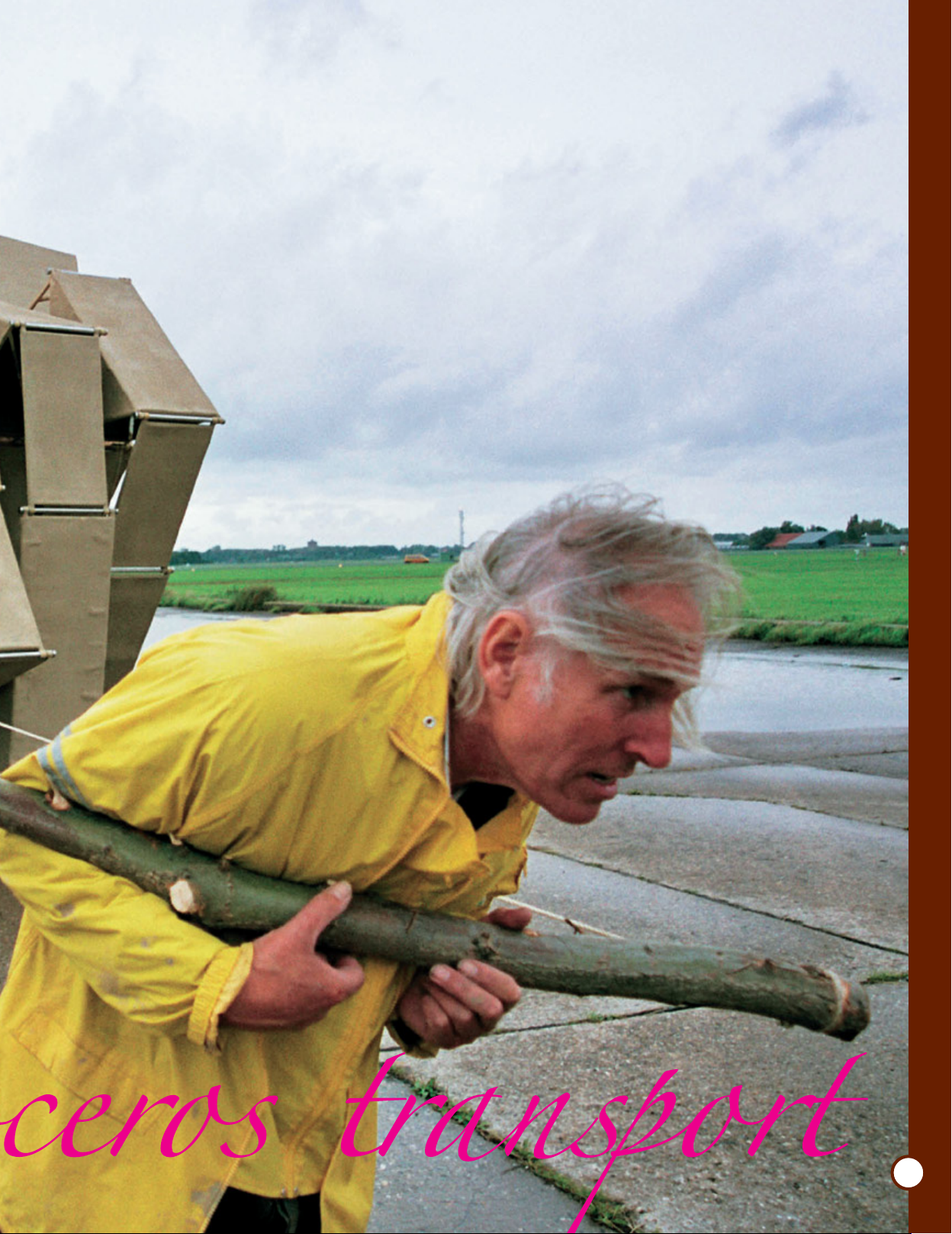
Jansen pulls the Rhinoceros Transport
to test its walking mechanism.
JR. SCIENTIST
2
Page 3
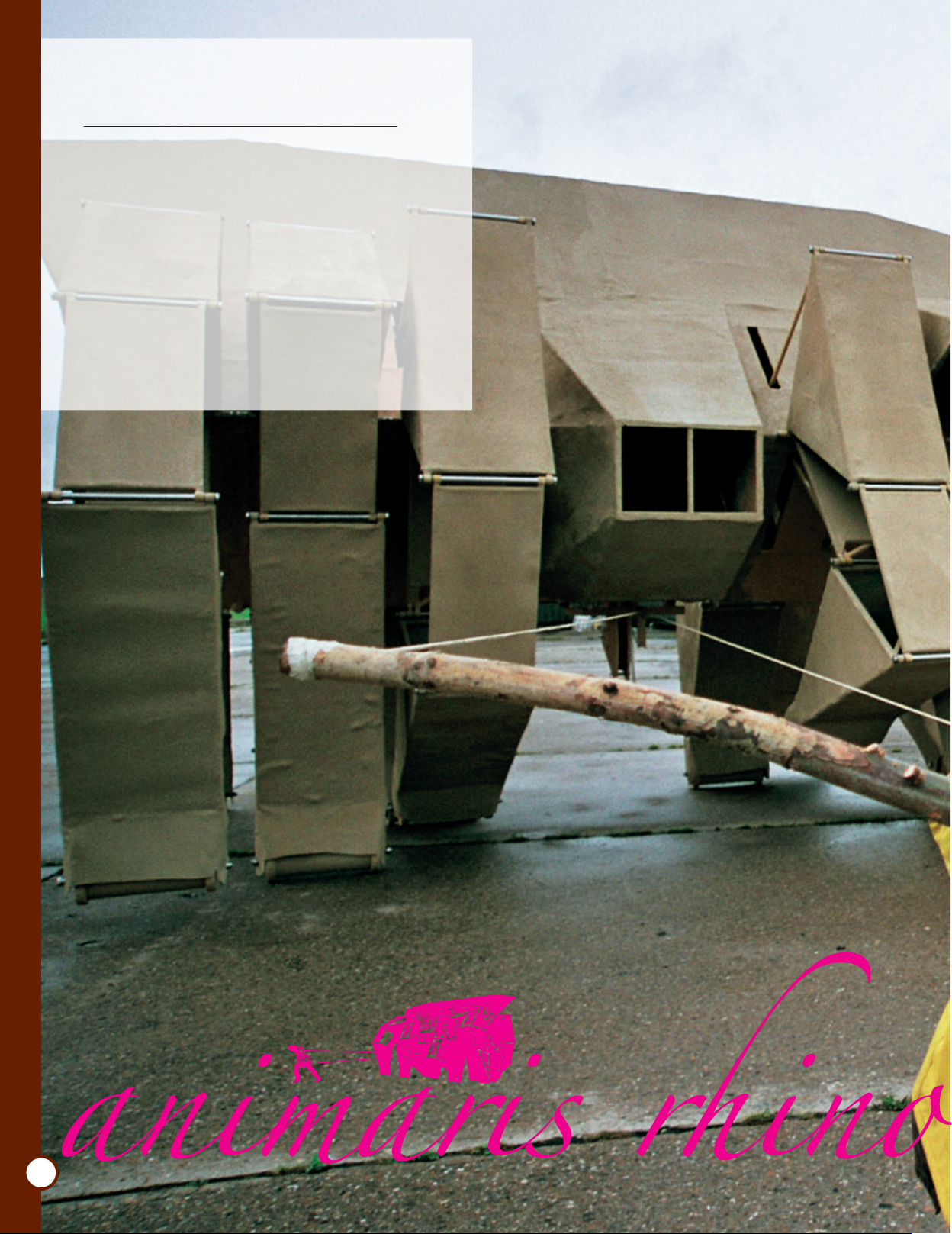
Giant Beest
"Animaris Rhinoceros Transport"
-The Secret of Its Birth
This kit was designed after "Animaris Rhinoceros Transport". It is the largest
Strandbeest in history with 6m in length, 5m in width, 4.7 m in height, and 3.2 t
in weight. The beest walks by the wind caught in the wing like panel attached
at the top. How did this beest come about? We are going to search the
secret of its birth.
Cooperation/ Theo Jansen [www.strandbeest.com] Media Force Ltd. [theojansen.net]
Photograph/Loek van der Klis [loek@loekvanderklis.nl]
Text/Gakken Editorial Team
Theo Jansen
Jansen was born in 1948, in
Scheveningen in the
Netherlands. He studied
physics at the Delft
University of Technology
and was involved in many
projects that involved both
art and technology. He has
been creating a series of
kinetic art, Strandbeests,
since 1990. Today, Jansen
is one of the internationally
recognized artists.
MINI RHINOCEROS
3
Page 4
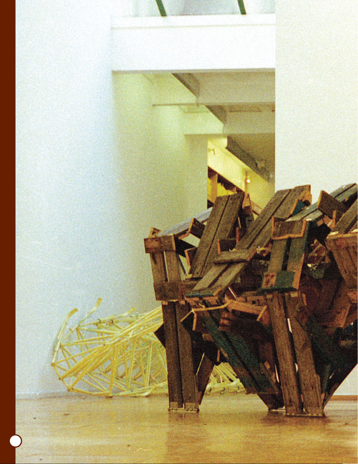
It all began from a
wooden pallet
Jansen started creating the Strandbeests in 1990. The
history of the beests is categorized in several periods.
From 1997 to 2001 is called the Lignatum (wood in
Dutch) period. Jansen experimented with wooden
pallets as the principal construction material.
The wooden pallets that Jansen utilized are those
common pallets for the forklifts that are often seen at a
warehouse or a manufacturing plant. He noticed the
pallets' sturdy structure that can withstand pressures
from all directions and substituted for the
plastics pipes.
At the time, Jansen was testing a
theory that the friction at the leg joints
can be minimized by changing the
overall length of the legs. The longer a
leg becomes, the smoother a leg
operates. However, longer legs made a
beest into a giant and the plastic pipes
tend to collapse as the beest becomes
bigger.
JR. SCIENTIST
4
Page 5
CG version of Animaris Rhinoceros Tabloi:
The height of this design is an advantage
by receiving stronger wind and
minimizing the joint friction. Height 4.5m,
length 6m, and width 4m.
CG version of the first generation
Rhinoceros, Animaris Rhinoceros Vulgaris
He needed to find out either a different structural designs or an
alternative materials. He was attracted to the wooden pallets.
Jansen calls this particular deviation "an affair". He was
Animaris Spissa Carta: This beest is
made of cardboard. Height 0.3m, length
0.4m, and width 0.4 m.
seduced by wood as a building
material instead of his long time
companion, plastic pipes.
The series of beests created in
this period had quite a different
and unique look among all the
beests in history. The heavy
and bulky structures are
associated with the image
of the rhinoceros. The
name "Animaris
Rhinoceros" was given
to this series.
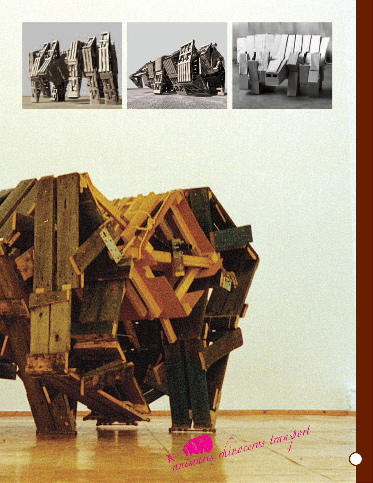
First a prototype was
developed using CG
(computer graphics)
technology, then the real
Animaris Rhinoceros
Lignatus was constructed
using wooden pallets.
Though this is made from a
new material, wood, Theo
Jensen's 13 holy numbers are
used throughout the
calculations of mobile parts of
the structure.
Thus, despite its unique
appearance, Animaris
Rhinoceros truly belongs in the
beest family. Later, the original
Rhinoceros Lignatus series
evolved into the Animaris
Rhinoceros Transport with steel
bone structures.
MINI RHINOCEROS
5
Page 6
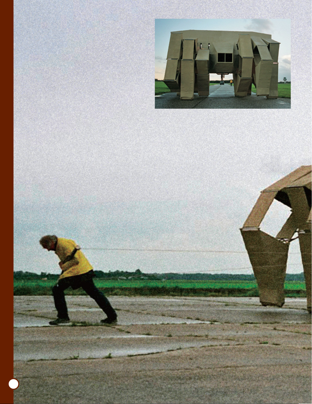
The Animaris Rhinoceros Transport was tried out
in 2004. This tryout version was developed as the
final model in the Rhinoceros family after Jansen's
affair with wood was over. Powder coated steel
was chosen for the skeletal structure due to its
sturdiness. The surface of the body is coated with
polyester. The wheeled feet can support the
massive weight while reducing friction with the
ground.
There is a space for people to ride inside. Jansen
calls this a "transportation vehicle in the tundra".
The tryout took place at north Leiden, A city in
the southern Netherlands. The usual tryout spot,
the beach, was not ideal for this massive structure
because there was a likelihood of getting stuck in
the sand. The long runway of the former
Valkenburg Airport was chosen because the vast
clear field and hard leveled ground would bring
the best wind condition for this experiment.
The Transport was taken out from a container to
the runway. Initially, Jansen himself pulled the
beest for a trial walk so that he could make sure
the joints functioned and checked for any
troubles. Everything worked fine! The wind
started to pick up. The massive feet started move.
The beest's feet moved lighter than expected.
The beest gained so much speed that some of the
junctions gave way!
Receiving the wind from behind on the
wing, the Rhinoceros walks effortlessly.
It was a complete success! The largest beest in
history, "Animaris Rhinoceros Transport" marked a
significant footstep in the history of evolution.
JR. SCIENTIST
6
Tryout on the runway of a former airport
Page 7
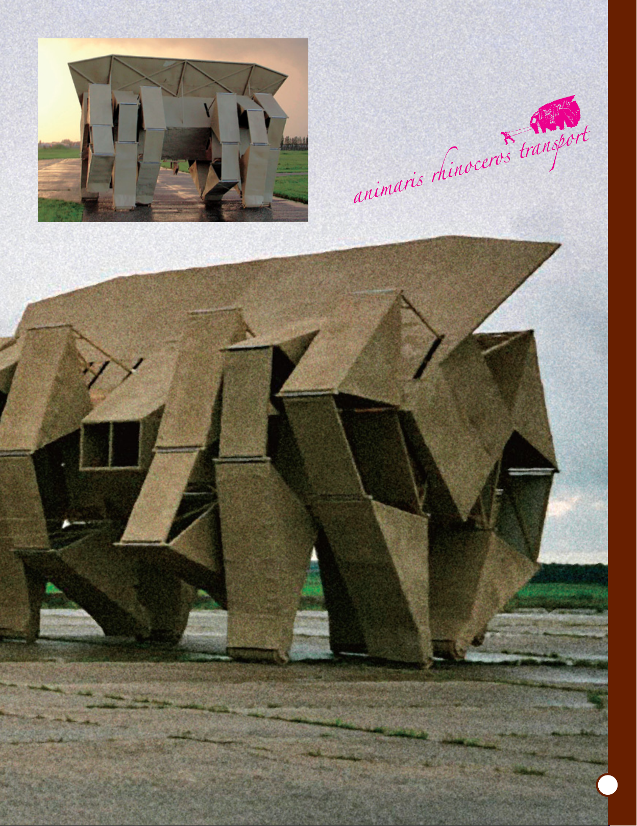
The mighty backside.
MINI RHINOCEROS
7
Page 8
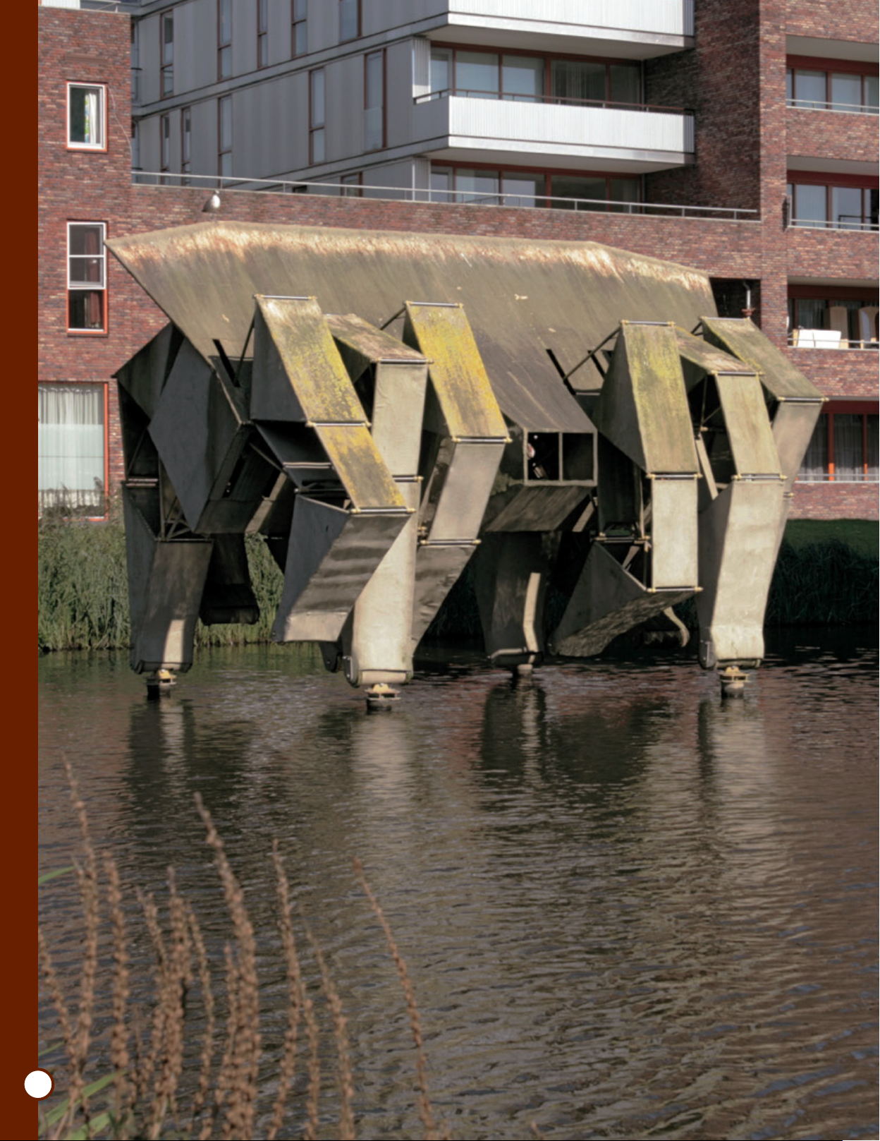
Currently, the Transport is
stationed in the canal for
display.
permanent exhibit
at a park
JR. SCIENTIST
8
and Now…
Page 9

The Transport is exhibited in the courtyard of
apartment complex developments in the suburb of
Amsterdam. It is stationed there without walking
any longer. It is a fossilized beest now. During the
opening event for the installation, the children had
a chance to climb in the beest; the news caught the
attention of many people.
The growth of moss on the
polyester surface reminds us of the
passing time. The magnificent
statue is still enjoyed by many
people in the neighborhood. Its
DNA is transferred and very much
alive in this "Mini Rhinoceros"
Opening event for the
Transport in Hassenfeldt,
suburb of Amsterdam.
Photographed from the backside. The growth
of moss shows that the time has passed.
Photographed from the side. It looks as if it
will start walking right at this moment.
MINI RHINOCEROS
9
Page 10

Witness the birth of the newest artificial life form, the strandbeest!
Netherlands
Scheveningen
Scheveningen is the birth place of
Theo Jansen and his creations, the
strandbeests. Most beests take
their first steps right here at
Scheveningen.
Amsterdam
Rotterdam
Germany
France
JR. SCIENTIST
10
Appearing at the coast of the Netherlands,
Animaris Gubernare
Page 11

In May 2011, the strandbeest,
Animaris Gubernare, first
appeared at the
Scheveningen coast in the
Netherlands. With a body
length of over 10m, this is
one of the largest
strandbeests. As usual, the
beest is made from various
plastic materials: yellow
tubes are used for the
skeletal structures and
nervous system, PET bottles
for the stomach, and vinyl
sheets for the wings. Will
the master of kinetic art,
Theo Jansen succeed in this
test walk?
Cooperation/Theo Jansen (www.strandbeest.com)
Media Force Ltd. (theojansen.net)
Photo/Loek van der Klis (Loek@Loekvanderklis.nl), Uros Kirn
Edit,Text/Gakken Editorial Team
MINI RHINOCEROS
11
Page 12

Sun shines through the
beautiful plastic skeletal
structure of a beest.
JR. SCIENTIST
12
Page 13

Jansen holds a PET bottle stomach of the beest.
The moment of birth
of the new beest
All the parts manufactured at Jansen's
workshop are brought to the beach as
units and assembled and tested on the
beach. Excess friction or air leakage
will prevent the beest from walking.
The beest is recognized as alive only
when it takes its first step on this
beach. The wind is picking up. The
wings on the back capture the wind
and they move gracefully. Each sway
of the wings charges the wind power
into the stomach of the beest made of
PET bottles.
The pressure inside the bottle
increases. Now everything is
ready. The compressed air in the
bottle is released to the structure.
The plastic tube pistons rotate
the cranks. We can hear the
crank operating. Its feet slowly
start moving and the support
sticks assist the stride of the
beest. A new artificial life form is
born. This is a divine creature full
of grace.
Jansen's beloved dog, Murphy
is pictured in the foreground.
The two life forms look as if
they are communicating with
each other.
MINI RHINOCEROS
13
Page 14

Nose
Four wing like pieces are arranged to
create aerodynamic flow.
This portion always points into the wind. Jansen calls this part the nose.
The nose prevents the beest from falling by a sideways gust.
A wing is also built on a plastic pipe
skeleton.
JR. SCIENTIST
14
Gubernare is a
governor of
the wind.
A prominent feature of this new beest is
the nose, the wind sensing part. The
beest always turns its nose into the wind.
The beest turns against the wind and
walks not only back and forth, but
diagonally. It governs its own motion, so
the name Gubernare (means govern in
Latin) was given. Now, another sense was
granted to the beest: the sense to detect
the wind's direction. Strandbeests are
evolving.
Tip of the leg
(Foot)
The pipes are shaped so that the foot rocks back and
forth. It is important to minimize the load on the feet.
These feet carry the massive weight of the beest. The feet
don't get buried into the sand either.
Page 15

Wings
Wings flutter in the
wind and feed air into
the stomach of the
beest. The wing
material is custom
made UV proof plastic
sheets. It is important
to protect the wings
from deterioration by
UV rays since the
beest belongs in the
outdoors.
The compressed air in the PET bottles expand
the wings.
Walking Stick
The walking sticks
act like ski poles.
A stick pushes
against the
ground and the
reaction force
pushes the body
back up. The
sticks help the
feet to minimize
the friction.
Jansen checks the wings' expansion function.
PET bottle stomachs
The stomachs are separated into two groups.
One group is located at the center of the body,
the other group is at the hind side. There are 94
bottles altogether.
MINI RHINOCEROS
Combined with the
other parts, the
sticks make the beest
walk back, forth, and
diagonally.
There are valves on the PET bottles. The bottle keeps
collecting the air until the valve opens.
15
Page 16

How to Assemble and Use the Supplement
Assembly time: Approximately 1.5 hours
Theo Jansen's
Mini Rhinoceros
Parts in the Kit
Lower triangles
(12)
12)
Single-action rods(lower,
12)
Lower triangle
covers (12)
Separate the parts from the plastic trees that they come attached to and arrange them as shown in
the picture.
Upper triangles
(12)
Frames (6)
Upper triangle covers
(12)
Right frame
(with gear)
Connecting rods
(inside,12)
Crankshafts (2)Single-action rods (upper,
Connecting rods
(outside,12)
Left frame
JR. SCIENTIST
16
Cogwheel (A)
Cogwheel (B) Cogwheel (C)
Metal shafts (2)
Rotating shaft (white)
Blades (6)
Things you will need
Scissors, utility knife, etc.
Cogwheel
shaft
CAUTION
Take necessary caution when handling parts with pointed edges. There is a risk of
injury.
Be careful when using the smaller parts so that you do not put them in your mouth
and accidentally swallow them. There is a risk of suffocation.
Keep this kit out of the reach of small children when not in use.
* Please read the instructions and cautions thoroughly before use.
* For your safety, be sure to follow the instructions in this manual. In addition, do not
use any parts that have become damaged or deformed during use.
Fasteners
(6, including two
spares)
Fan base (right) Fan base (left)
Please be sure to read the following instructions before
assembling this kit.
Leg tube
(Separate them to 13 for use. One is
kept as a spare.)
Flange
Tube (small)
Page 17

Assembling the Legs of
Mini Rhinoceros
1.
Separate the leg tube at the cut lines.
4.
Set the inside and outside connecting rods to
the upper triangle cover and attach the upper
triangle on it.
Upper
triangle
Cut lines are on both sides.
When the cut lines are not
apparent, gently stretch the leg
tube to the right and left.
2.
Insert the leg tubes into the lower triangles.
Insert all twelve leg tubes in the same way.
Leg tube
Leg tube
There are thirteen leg tubes.
Only the twelve of them are
used for assembly. One is for
spare.
Lower triangle
Connecting rod
(outside)
Upper triangle cover
5.
Connecting rod
(inside)
This completes one leg. Make a total of
twelve of these units.
Connecting rod (inside)
IMPORTANT
When attaching the connecting rods, make sure that they
are attached in the correct direction.
Mounting the Crankshafts
3.
Firmly push the leg
tube all the way to the
bottom.
Set firmly the inside and outside connecting rods
on the lower triangle, and then attach the lower
triangle cover on it.
Lower triangle cover
Connecting rod
(outside)
Connecting rod
(inside)
Lower
triangle
IMPORTANT
Set the connecting rods
in the direction so that
its hole is located at the
upper side.
The hole is located
at the upper side.
Connecting rods need to be set so
that "the circle mark used to push out
the part from die" is located inside and
the smooth surface is located outside.
on the Frames
Attach the crankshafts to the right and left frames. Snap
them into place, taking care to ensure that they are
attached in the correct direction.
There is a notch
on the tip.
Right frame
Crankshaft
It's a good chance to know that a crankshaft is made of crank axes for
rotation (with frames attached), crank pins moving in a circular motion
(with rods attached) and crank arms to connect them together.
IMPORTANT
The two crankshafts are exactly the
same, but they are to be oriented in
opposite directions when attached as
they will be linked together at the
end. Confirm that you have connected
the two crankshafts together as shown
in the picture. Pay attention to the
positions of the front and back sides of
the left and right frames.
Metal shaft is attached.
There is a protrusion
on the tip.
Left frame
Crankshaft
MINI RHINOCEROS
17
Page 18

Assembling the Right Frame
and Legs
Start working on the right frame first. Attach two
1.
legs to the protrusions on the right frame. Be sure to
check the orientation.
Lower triangle Lower triangle
4.
Attach the single-action rods (upper) to the left and
right upper triangles. Pay attention to the direction
of the notch.
Upper triangle
Attach the frame to the holes on the upper triangles
in the direction as shown in the figure.
2.
It may be
difficult to attach
the frame to the
upper triangle as
the crankshaft may
get in the way.
Right frame
Upper triangle
Insert the protrusions on the
right frame into the holes on the
upper triangles, as shown in the
figure.
Orient the frame with the
protrusion with the
indented tip side up when
attaching.
Indent
Frame
Upper
triangle
Notch Notch
Single-action rod (upper)
Push each of the single-action rods (upper) onto the connecting rods so
that they snap into place with the notch on the opposite end facing
inward.
Attach the single-action rod (upper) on the right to
the first crank pin of the crankshaft.
Single-action rod (upper)
5.
Crankshaft
Crank pin
Single-action rod
(upper)
Upper
triangle
JR. SCIENTIST
18
Attach the frame to the second crank axis of the
crankshaft so that it snaps into place.
3. 6.
Crankshaft
Frame
Single-action rod
(upper)
Snap together.
Attach the single-action rod (upper) on the left above
the single-action rod attached on Step 5.
Crankshaft
Upper
Snap
together.
Lower
IMPORTANT
The single-action rod on the left side
is to be attached above the singleaction rod on the right side. Be sure to
attach them correctly.
Page 19

From this step onward, the figures are drawn with the lower triangle (with leg tube)
facing out toward you.
Attach the single-action rods (lower) to the lower
triangles. Be sure to check the orientation.
7.
This is a picture of the
unit assembled
correctly up to this
point.
Lower
triangle
8.
9.
The notch is directed slightly
toward the inside.
There is a step.
Single-action rod
(Lower)
Smooth surface
Attach the single-action rod (lower) on the right side
to the first crank pin on the crankshaft. Attach it
between the two single-action rods (upper) that were
attached in Steps 5 and 6.
Single-action rod
(upper)
Attach the single-action rod (lower) on the left side
just above the single-action rod (lower) that was
attached in Step 8.
Single-action rod (Lower)
Single-action rod
(lower)
Single-action rod (upper)
Lower
triangle
The figures below are drawn with the upper triangle facing out
toward you once again.
Attach the two legs to the protrusions on the
10
11 .
IMPORTANT
Orient the frame with the protrusion with the indented tip side up when attaching.
frame in the same way as Step 1.
.
Attach in the same direction as the two legs that have
already been attached.
Attach the frame to the legs and fix it to the
axes of the crankshafts. Then, attach four
single-action rods in the same way as described
in Steps 4 to 9.
Make sure to attach in the right locations and
directions.
Frame
Indent
Single-action rod (lower)
Make sure that the two
single-action rods (lower) are
located between the two singleaction rods (upper).
It may be difficult to attach
the frame as the crankshaft may
get in the way.
MINI RHINOCEROS
19
Page 20

12
Attach two legs to the protrusions on the
frame as in Step 1.
.
Assembling the Left
Frame and Legs
Assemble the left frame and legs. Attach two legs to
1.
the protrusions on the left frame. Be sure to check the
orientation of the left frame.
13
Attach in the same
direction as the two legs that
have previously been
attached.
Attach the frame to the legs in the direction as
shown in the figure. Next, attach four single-
.
action rods in the same way as described in Steps
4 to 9.
IMPORTANT
Orient the frame with the protrusion with the
indented tip side up when attaching.
Frame
Indent
Lower triangle
Lower
triangle
Insert the protrusions on the left
frame into the holes on the upper
triangles, as shown in the figure.
Attach the frame to the legs in the direction as
2
shown in the figure. Make sure to attach the left
.
frame assembly in the opposite direction as the right
frame assembly.
Leg
Left frame
Lower triangle
Leg
IMPORTANT
Orient the frame with
the tip with a hole side
up when attaching.
Lower
triangle
JR. SCIENTIST
20
Six legs are
assembled with
the right frame.
It may be difficult to
attach the frame as
the crankshaft may
get in the way.
Attach the frame to the second crank axis of the
3
crankshaft so that it snaps into place.
.
Frame
Frame
Crankshaft
Insert up to here.
Page 21

Follow the assembly procedure of the right frame
4
from Step 4 onward except with the left frame
.
oriented in the direction opposite to that of the right
frame.
Follow the same procedures for attaching the singleaction
rods for the right frame assembly.
Frame
Six legs are
assembled with
the leftframe.
Insert the two metal shafts into the frame and
pass them through the entire body so that they
2
.
stick out on either side.
Shaft
IMPORTANT
Orient the frame with the tip with a hole side
up when attaching.
Shaft
Make sure that the shafts are protruding
a little from left and right ends of the frame.
Attach the fasteners to both ends of the
shafts.
3
.
Assembling the Body
Assemble the right frame and left frame units.
Line up the joint parts on the frames and
1
.
crankshafts.
Left frame unit
Right frame unit
Fastener
Fastener
4
Fastener
Fastener
Make sure the shaft ends are protruding by
approximately 4 mm from the tip of fasteners.
Attach the cogwheel shaft to the right frame. Line
up the pin on the cogwheel shaft with the hole on the
.
frame and insert it into the hole up to the first
frame. Then, turn the cogwheel shaft 90° so that it
clicks into place.
Right frame
Frame
IMPORTANT
After assembling them together, try to rotate the crankshaft. The frames are attached
together correctly if the six legs move at different timings. If the legs of the left and
right frames move in the same way, turn the crankshaft joint part by 180° and
connect them again.
Cogwheel shaft
Turn the cogwheel
shaft 90° after
inserting it all the
way in.
MINI RHINOCEROS
21
Page 22

5
Attach the cogwheels (B) and (C) to the right frame.
Be sure to check the orientation.
.
Gear
Cogwheel (B)
Attach the cogwheel (B)
to the right frame so
that the teeth on the
outside cogwheel engage
with the teeth on the
gear on the right frame.
Cogwheel (C)
2
After inserting all six blades in the same way,
attach the fan base (left) on the opposite side. This
.
completes the sirrocco fan.
6
Attach it to the tip
of the crankshaft.
Right frame
Attach the cogwheel (A) to the cogwheel shaft. Snap
it into place, taking care to ensure that it is attached
.
in the correct direction.
Cogwheel shaft
Cogwheel (A)
3
Right
frame
Fan base (left)
Orient the fan base (left) with the
protrusion facing down, and insert the
blades into the grooves in the same way
as above..
Attach the sirrocco fan to the body.
.
Left frame
JR. SCIENTIST
22
Assembling the Sirrocco Fan
Attach the blades to the fan base (right).
1
.
Orient the fan
base with the
protrusion side
up when
attaching.
Fan base (right)
Large
protrusion
IMPORTANT
There are two protrusions on the tip of the
blade. Insert the blade so that its smaller
protrusion is located outside.
Blade
Small
protrusion
Attach the fan to the left frame first, and then line up the
protrusion on the fan base (right) with the cogwheel axis on the
right frame to attach the fan.
Completed
Page 23

Getting the Mini Rhinoceros Walk
1
Using wind to make it move
.
The sirrocco fan rotates in the same direction as the wind either at
its back or in its face. The Mini Rhinoceros starts to walk when the
sirrocco fan rotates.
When wind is blown on
the Mini Rhinoceros in the
direction shown by the
arrows, the Mini Rhinoceros
starts to walk toward the
right. The walking direction
is always the same no
matter the direction in
which the wind blows.
Walk towards this
direction.
2
Using the rotating shaft to make it move by hand
.
Use the tube (small) to connect the rotating shaft and flange
together.
Remove the sirrocco fan to reduce weight of the load and insert the
rotating shaft into the crankshaft that does not have a gear (left
frame). When you turn the rotating shaft, the Mini Rhinoceros
starts to walk.
Rotating shaft
Tube
Insert it into the crankshaft
Flange
You can wave a round paper fan or a folding fan toward it or use an
electric fan to blow air at it. It is recommended that you use the cool setting
if using a hair dryer. (Do not use hot air as it may change the shape of the
blades.)
Q&A
Q: The crankshaft gets hard to turn at one spot in
each revolution.
A: Confirm the assembling order of the single-action rods.
Especially check the order of the upper single action rods.
Q: I tried the solution suggested above, but it didn't help.
A: Disassemble the right frame unit and left frame unit. Find
the causes of trouble by removing the single-action rods from
the frame unit on the side that moves more slowly.
Q: The Mini Rhinoceros does not move right.
A: Refer to page 21 and check the movement of the left and right
frame units. When the leg movement of the left and right
frame units are synchronized, reassemble the frame units
after rotating the joint part of the crankshafts 180°. Confirm
that the six legs on a unit move differently.
If it moves sluggishly, remove the cogwheel (A)
and cogwheel (B) and try again.
Q: The sirrocco fan rotates slowly.
A: Confirm that the cogwheel shaft and cogwheel (A) are
engaged properly.
The cogwheel (A) should snap into place. If there is rattling,
remove the cogwheel (A) and try to reattach so that it snaps
into place. Check the notch on the tip of the cogwheel shaft. If
it is oriented vertically, the cogwheel shaft and cogwheel (A)
should be attached together properly.
Q: The rotating shaft is hard to turn when rotated by hand.
A: Try to make the Mini Rhinoceros walk with the sirrocco fan
removed.
MINI RHINOCEROS
23
Page 24

P38-GK022-81001002
 Loading...