

Page 1
®
D
ENG
F
NL
IT
ES
DA
Montage- und Betriebsanleitung Schiebeschlitten
Assembly and Operation Manual
Sliding Carriage
Instructions de service relatives au chariot coulissant
Montage en gebruiksaanwijzing Afkortgeleider
Istruzioni per l'uso ed il montaggio della slitta di
spinta
Instrucciones de montaje y uso - Carro deslizante
Betjeningsvejledning Tapslæde
TF 900/TF 904
D
Achtung! Lesen Sie diese Anleitung vor der Installation und Inbetriebnahme aufmerksam durch.
ENG
Attention! Carefully read through these instructions prior to installation and commissioning.
F
Attention! Prière de lire attentivement la présente notice avant l'installation et la mise en service.
NL
Attentie! Lees deze instructies voor de installatie en ingebruikname aandachtig door.
IT
Attenzione! Prima dell'installazione e della messa in esercizio, leggete attentamente e completamente queste istruzioni.
ES
Atención! Lea atentamente estas instrucciones antes de la instalación y puesta en marcha.
DA
Bemærk! Læs denne vejledning opmærksomt igennem inden installationen og idrifttagningen.
115 160 0154 / D/ENG/F/NL/IT/ES/DA / 4000 / 2.0
Page 2

Contents
1 Scope of Application
2 Specifications
3 Product Liability/Warranty
4 Safety Information
5 Installation
6 Operation
7 Care and Maintenance
8 Spare Parts List
1 Scope of Application
This Sliding Carriage is intented for use with the Elekta Beckum Spindle Moulder models TF900/TF904. It is used
for working across the endgrain of timber having a square or rectangular crossection.
- Please observe all relevant safety regulations for the use of spindle moulders applicable in your area.
When in industrial use in the U.K. use of this accessory falls under the 1974 Woodworking Regulations. In the
interest of health & safety of the machine user we recommend you study and follow these regulations.
We would also draw your attention to the booklet "Woodworking Machines Regulations 1974-Guidance on
Regulations" ref. L4 /ISBN 0118855921) published by HSMO.
ENG
2 Specifications
Table size: 280 x 525 mm
Carriage travel: 700 mm
Fence: adjustable 45° through 90°
Graduation: 1°
Carriage guides: 4 rollers, on ball bearings
Max. allowable workpiece weight: 20 kg
Mounting: quick-action locks
Workpiece clamping: quick-action clamp
3 Product Liability/Warranty
This product carries a 12 month manufacturer warranty under the prevailing legal provisions, which may vary from
country to country. The warranty period begins with the date of the original purchase by the end user. Proof of
purchase should be retained and must be presented in the event of a warranty claim. This warranty excludes and
does not cover defects, malfunctions and failures caused by natural wear, overload, unreasonable use or failure
to provide reasonable and necessary maintenance.
In case of a defect notify your dealer or Elektra Beckum distributor, who will decide how to handle your claim.
Warranty claims can only be taken care of by your Elektra Beckum dealer or authorized service centre.
This product or any of its parts should not be altered or changed from standard specifications. The user of this
product shall have the sole responsibility for any malfunction which results from improper use or unauthorized
modification from standard specifications, faulty maintenance, damage or improper repair by anyone other than
qualified person approved by Eleketra Beckum or its representatives.
4 Safety Instructions
Feeding the workpiece with a sliding carriage is considered semi-mechanical feed. The cutterheads and moulding
tools used must be approved for mechanical feed. Always perform such moulding operation with the cutterhead
running at counterrotation, i.e. the cutterhead is turning against the direction of feed of the workpiece. Always have
the workpiece firmly secured to the sliding carriage's table with the clamps provided.
Page 3
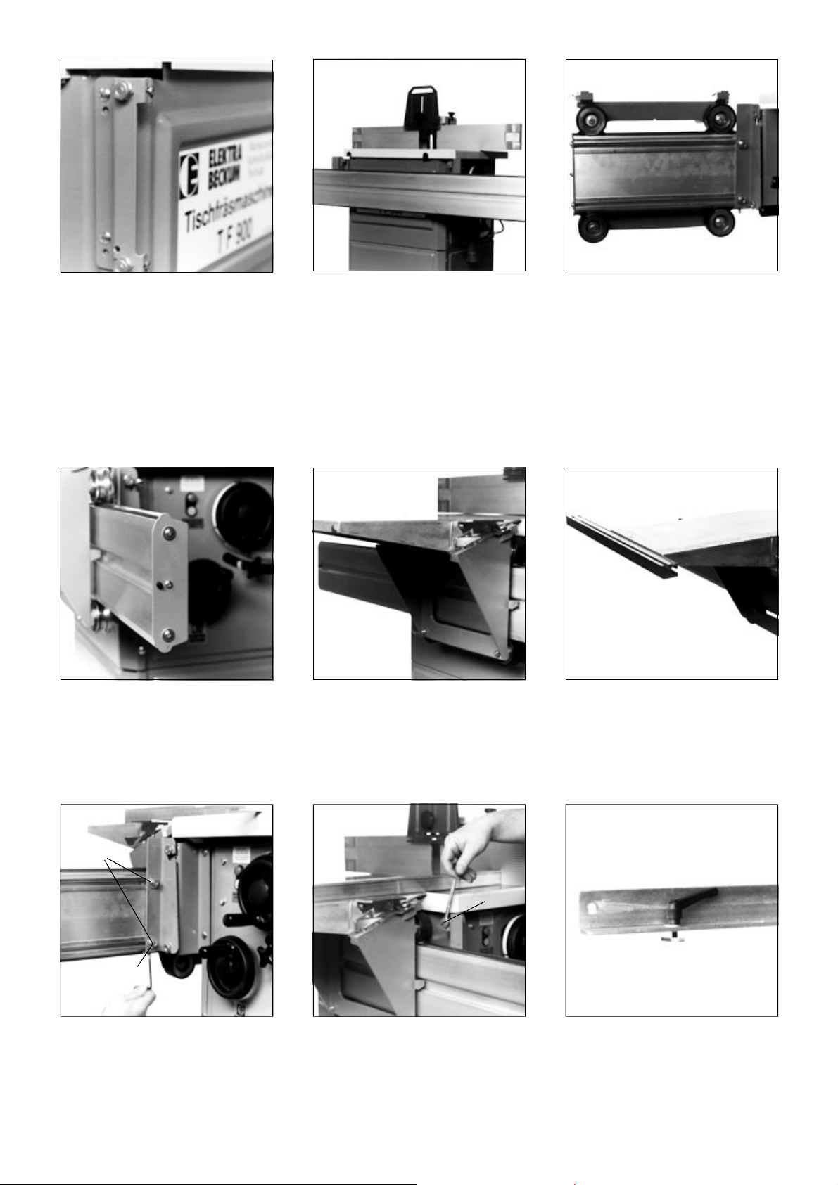
5 Installation
Fit the two crosshead plates (370/371) to
the machine housing.
Use 4 each
cup square neck bolt M 6x20
flange nut M 6
Reinstall backstop plate. Place sliding carriage table onto traversing
Hook roller carriage extrusion (358) with
both extrusion brackets (319 + 320) onto the
crosshead plates. If it is a tight fit remove
some paint from the slots in the extrusion
brackets.
Secure roller carriage extrusion by fixing the
rear extrusion bracket (319) to the crosshead
plate (371), to prevent unhooking.
Use 1 each
hexagen head bolt M 6x16
hexagon nut M 6
saddle and secure with the lock levers.
Loosely fit two cup square neck screws M
6x20 with washer Ø6.4, spring washer Ø6
and hexagon nut M6 to the two holes in the
front of the carriage table.
Remove the front backstop plate (360) and
slide traversing saddle onto the roller carriage extrusion.
Slide link bracket extrusion on the heads of
the just fitted cup square neck screws. At this
stage do not tighten the screws.
A
B
The carriage table should be set approx.
0.5 mm higher than the machine table. Set
with setting screws B. Loosen screw
holding rear extrusion bracket (319/371
and 320/370) to bracket before turning
setting screw B and tighten after setting.
Make trial cut to verify proper setting. After
setting is completed, tighten all 4 nuts
(408) M8 (A).
C
Alignment:
Set roller carriage extrusion parallel to the
machine table with both front and rear setting screws C. It does not matter if the
carriage table is higher or lower than the
machine table.
After successful parallel alignment tighten
the counter nuts on all 4 setting screws B.
Den Klemmhebel mit Unterlegscheibe durch
den Schlitz der Kulissenschiene führen und
den Stellgleiter aufschrauben.
Page 4

Fit slide washer into the groove of the link bracket extrusion. Insert pivot bolt and secure with
starknob screw.
Put cup square neck screws M 6x20 into the
slot of the fence extrusion an install the first
stop plate with a nyloc nut M 6. Bolt fence
extrusion to link bracket angle bar with 2
each cup square neck screws M 6x29, washers Ø 6 mm and 6 mm starknobs. Install
second stop plate.
Attach link bracket extrusion end plate (357)
with two pan head tapping screws to the link
bracket extrusion. Set fence square with the
machine's fence and set the link bracket
extrusion to the zero mark by moving it as
required.
- Exact setting is done with the setting screw.
6 Operation
Install support rod (375) to clamping plate
with hexagon nut M 12. Fit clamping plate to
the fence extrusion end.
Hardware:
2 ea. hexagon head screw M 6x35
2 ea. washer Ø 6
2 ea. starknob M 6 female.
Place clamping arm, with spring fitted in
groove, onto support rod and tighten ratchet
lever to hold in position.
Short work is held on the clamping plate
attached to the fence.
To work long stock the fence can be extended. Move the flipstop to the fence extension
extrusion before extending the fence.
The pivot bolt is replaced by the clamping
arm support provided, which is locked in
position with the starknob screw.
After removal of the clamping plate long
workpieces are placed directly on the sliding
table and held with the clamping arm mounted
as shown at right.
Page 5

7 Care and Maintenance
Regularly apply a light coat of oil to the guide bars. All grooves in the aluminium extrusions should be kept greased.
The deep grooved roller bearing of the traversing saddle are factory lubricated for life and require no maintenance.
8 Spare Parts List Sliding Carriage TF 900/TF 904
Pos. Description Size mm Stock-no.
301 Link bracket extrusion 600 139 320 1394
302 Angle scale 553 114 220 1247
303 Planing bed 287x525 139 020 6760
304 Fence extrusion 1410 139 320 4296
305 Ratchet lever M 8x20 700 6043 407
308 Lock lever, right 149 201 9425
309 Lock lever, left 149 201 9433
310 Traversing saddle 139 020 1237
311 Setting bracket 139 201 7573
313 Guide rail, left 149 201 9794
314 Guide rail, right 149 201 9719
315 Roller, c/w bearing Ø 65x28 201 020 0140
319 Extrusion bracket, rear 139 220 1315
320 Extrusion bracket, front 139 220 1307
323 Double collar nut SW 19x40 139 520 1286
324 Setting bolt SW 19x34 139 520 1448
325 Starknob M 6 700 002 5458
326 Cam bush, lower SW 30x25 139 520 1278
327 Roller bush, upper Ø 30x25 139 520 1260
329 Sliding washer M 8 Fl 16x5x60 149 202 4500
330 PVC roller cover 239 120 1377
331 Fence end plate 239 120 1628
332 Link bracket angle bar 740 148 540 0792
333 Clamp bracket 25x25x100 148 240 0821
334 Pivot bolt Ø 20x35 148 540 0830
335 Starknob screw M 6x16 700 105 9887
336 Serrated lock washer Ø 6.4 630 408 4047
340 Fence extension 140 139 320 1645
341 Fence extension extrusion 1520 139 320 1610
343 Starknob screw M 6x16 700 105 9887
344 Flipstop 201 020 0388
345 Flipstop guide plate Bl 0.88x16x70 139 220 1587
346 Knurled nut, Meplag M 6 624 2018 000
349 Stop plate Bl. 2x52x44 149 2097 752
350 Plug Ø 14x14 239 1203 906
351 End plate, fence extension 239 120 3760
357 End plate, link bracket extrusion 239 120 5801
358 Roller carriage extrusion 1500 139 320 5900
359 Guide bar 1500, round Ø 20x1499 148 211 3253
360 Backstop plate 139 220 5965
365 Scale 1410 1410 114 220 4700
366 Scale 140 140 114 220 4718
367 Scale 1350 1350 114 220 4726
370 Crosshead plate, right 138 210 0820
371 Crosshead plate, left 138 210 0839
Pos. Description Size mm Stock-no.
372 Flange nut M 6 620 911 4230
373 Clamping plate 138 011 0381
374 Glide piece 239 120 2772
375 Support rod 148 211 0521
380 Starknob screw M 8x28 700 101 7777
400 Pan head tapping screw St 2.9x9.5 617 203 9632
401 Pan head tapping screw St 4.8x16 617 200 1830
402 Hex. socket set screw,
flat point M 8x20 616 102 9309
403 Cup square neck screw M 8x20 611 001 7942
404 Washer Ø 8.4 630 500 2486
405 Hexagon nyloc nut M 8 620 200 2305
406 Hexagon head screw M 6x35 610 300 4916
407 Hexagon nut M 6 620 000 2219
408 Cup square neck screw M 6x20 611 000 0608
409 Hexagon nyloc nut M 6 620 200 2291
410 Washer Ø 6.4 630 001 6365
411 Hexagon head screw M 8x45 610 200 1085
412 Cap nut, self-locking M 8 620 807 3395
413 Countersunk head screw St 4.8x22 617 406 3948
414 Hexagon head screw M 6x40 610 3001 151
415 Split washer B 6 630 100 0276
421 Hexagon head screw M 6x16 610 301 5675
422 Cross rec. head drilling screw Ø 3.5x13 614 402 7270
424 Washer Ø 3.2 630 505 2335
425 Cup square neck screw M 6x16 611 000 0594
427 Cup square neck screw M 6x35 611 002 9436
428 Hexagon socket head
cap screw M 6x16 612 705 9193
429 Hexagon nut M 12 620 001 7992
430 Washer A 13 630 001 6705
640 Lock lever 138 040 0819
641 Lock bolt 148 540 0857
642 Pressure spring 705 100 5770
643 Circlip for shafts 6x0.7 640 007 1061
644 Starlock with cap Ø 8 701 612 3379
645 Clamping arm 138 040 0800
646 Tension spring 0.9x6x40.5 705 240 0877
647 Clamping arm bolt Ø 12 M 6x45 148 540 3732
648 Washer A 6.4 galv. 630 001 6365
649 Ratchet lever, female M 6 700 607 2385
650 Clamping arm support Ø 20x237 148 540 0849
651 Clamping pad Ø 35x14 705 740 0867
652 Bolt A 8x35 663 212 3360
Page 6

Winkelaanslagprofiel pos. 304
Vinkelanslag Pos. 304
Profilato di arresto angolare Pos. 304
Winkelanschlagprofil Pos. 304
Doorsnede A
Sezione A
Ausschnitt A /
Udsnit A /
Beachten Sie bei der Montage bitte den
Fixierpunkt "0"
Let u bij montage a.u.b. op afstelpunt "0"
Bemærk 0-punktet ved monteringen
Durante il montaggio tener presente il punto
di fissaggio "0“
Coulisseprofiel
Binario a glifo
Kulissenschine /
Vinkelskinne /
Stellschraube M6x40 Pos.414
Fixierpunkt "0"
Klemmhebel M8x20
Klemhevel M8x20
Kippgreb M8x20
Afstelpunt "0"
Leva di fissaggio
Stelschroef M6x40 pos. 414
Indstillingskrue M6x40 Pos. 414
Vite di registro
0-punkt
Punto di fissaggio "0"
Page 7

13-217 445, Fax: +40-13-214 505
-
Dilex d.o.o.,
Orginceva ut. 17, SLO-51113 Ljublijana
Remtech Spol. S.R.O.,
Vinice 293, SK-90021 Svaty Jur
Tel.: +42-1-744 971 981, Fax: +42-1-744 971 291
Agent Trade, S. C., S.R.L.,
Aleea Bran Nr. 2, BL. 92, P., Ap. 47,
RO- 751552 Bucuresli 4
Metabo s.r.o.,
Kralovicka 544, CZ-25001 Brandys nad Labem
Tel.: +42-202-804 458, Fax: +42-202-804 456,
e-mail: Miranda@metabo.cz,
Internet: http://www.metabo.cz
Tel.: +40
Tel.: +386-61-168 16 20, Fax: +386-61-168 16 16
EB_Adr1B.fm
c
Bolas - Máquinas e Ferramentas de Qualidade, S.A.,
Rua 8, Lotes 8, 10, 12, P.O. Box 53,
P-7001 Évora-Codex
P
s
Metabo Danmark A/S,
Tel.: +351-66-74 93 00, Fax: +351-66-74 93 09,
e-mail: bolas@mail.telepac.pt
K
R
Marielundvej 48 C, DK-2730 Herlev
Tel.: +44-84-13 55, Fax: +44-84-86 04,
e-mail: brasmus@post10.tele.dk
Profilma-Import A/S,
N
O
HDF-Paulsson AB,
Box 525, Svaravaregatan 5, S-30180 Halmstad
Tel.: +46-35-154 400, Fax: +46-35-121 780
Nofa OY, P.O.Box 28,
Hannuksentie 1, FIN-02270 Espoo
Postboks 536 Nanset, Sophus Buggesvei 48,
N-3252 Larvik
Tlf.: +47-33-114 777, Fax: +47-33-114 108
S
Tel.: +358-9-804 851, Fax: +358-9-809 485
J
91-578 47 72
-
28,
GdyĖska
SzczeciĖski
z o.o.J.V., ul.
EB Nefro KFT,
EB- Polska,
Spółka
PL-73110 Stargard
p
Futo U. 70, HU-3508 Miskolc
Tel.: +48-91-578 47 72, Fax: +48
h
Extra Industrial Goods,
Tel.: +36-46-362 264; +36-46-366 363,
+36-30-450 618, Fax: +36-46-362 761
a
ITA Ltd.,
Balakirevskij Pereulok 19, str. 1, RUS-Moscow
Tel.: +7-95-737 93 11; +7-95-737 93 12,
+7-95-737 93 13, Fax: +7-95-737 93 14,
Rr. Fadil Rada 88, AL-Tirana
Tel.: +355-42-330 62, Fax: +355-42-330 63
AS Mecro,
Peterburi tee 44, EST-11415 Tallinn
Tel.: +372-6-201 101, Fax: +372-6-201 112
e
r
e-mail: ita1@online.ru
Elektra Beckum AG,
D
Metabo UK Ltd., 25 Majestic Road, GB-SO 16 OYT
Tel.: +44-2380-732 000, Fax: +44-2380-747 500
Daimlerstraße 1, D-49716 Meppen
Tel.: +49-1803-333 456, Fax: +49-1803-333 457
A
Lurem MACHINES à BOIS,
G
F
S.A. Ferunion N.V., 19-23, Rue de L‘Escaut /
Scheldestraat 19-23, B-1080 Bruxelles/Brussel
Tél.: +32-2-427 71 10, Fax: +32-2-425 37 21,
e-meil: general@ferunion.be
Metabo Nederland b. v.,
Keulschevaart 8, NL-3621 MX Breukelen,
Zone Industriell/BP 1, F-617000 Domfront
Tel.: +33-2-333 757 00, Fax: +33-2-333 720 70
B
Postbus 180, NL-3620 AD Breukelen,
H
Metabo Kistool AG,
Badener Str. 816, CH-8010 Zürich
Tel.: +41-1-437 82 80, Fax: +41-1-437 82 77,
e-mail: metkis@swissonline.ch
Fischknecht, Markus Schweisstechnik,
Marktgasse 6, 9050 Appenzell
Tel.: +41-71-787 14 05, +41-79-696 36 44,
Fax: +41-78-782 07
Carlo Stechel & Figli S.R.L.,
Tel.: +31-3462-642 44, Fax: +31-3462-635 54,
e-mail: marianne@metabo.nl
C
Via Buozzi 22, I-20097 San Donato Milanese (MI)
I
Herramientas Metabo, S.A.,
Polígono Ind. N°6, Parcela 16,
E-28935 Móstoles (Madrid)
Tel.: +34-91-616 57 67, Fax: +34-91-616 43 55,
e-mail: metabo-madrid@accesosis.es
Kestra S.A. Soldadura,
Polg. Ind. La Ferreria, C.Del Treball, No. 19,
E- 08110 Montcada I Reixac,
Tel.: +39-02-556 001 11, Fax: +39-02-556 003 22,
e-mail: a.casano@stechel.it
Tel.: +34-935-750 030, Fax: +34-935-753 394
E
 Loading...