

Page 1

®
ENG
F
NO
FIN
SV
Operating Instructions Spindle Moulder
Instructions de service Fraiseuse de table
Bruksanvisning Bordfres
Käyttöohje pöytäjyrsinkone
Handledning bänkfräsmaskin
TF 100 M
ENG
Attention! Carefully read through these instructions prior to installation and commissioning.
F
Attention! Prière de lire attentivement la présente notice avant l'installation et la mise en service.
NO
Se opp! Vær så vennlig å først gjennomlese nøyaktig denne veiledningen før installasjonen og idriftsettelsen.
FIN
Huomio! Lue tämä ohje huolellisesti läpi ennen asennusta ja käyttöönottoa.
SV
115 160 0294 / ENG/F/NO/FIN/SV / 3000 - 3.0
Observera! Var god och läs noga igenom denna handledning före installering och idrifttagande.
Page 2

ENG
Contents
1 Specifications
2 User Responsibility
3 Standard Delivery
4 Optional Accessories
5 Final Assembly
6 Installation
7 Commissioning
7.1 1-Phase Power Supply
7.2 3-Phase Power Supply
7.3 Direction Of Rotation
7.4 Switch
7.5 Overload Protection
7.6 No-Voltage Release
7.7 Dust Collection
7.8 Dust Collector Automatic Start
8 Safety Information
9 Workpiece Dimensions
10 Scope Of Application
11 Tool Dimensions/Cutting Speeds
12 Jigs And Push Blocks
13 Controls
13.1 Definitions
13.2 Mounting A Tool
13.3 Spindle Speed Setting/Changing
13.4 Tool Height Setting
13.5 Fence And Fence Plate Setting
13.6 Cutter Guard Setting
14 Operation
14.1 Tools
14.2 Stock Prechecking
14.3 Moulding Strips
14.4 Moulding Boards
14.5 Making Tenons
14.6 Set-In Work
15 Care And Maintenance
16 Electrical Wiring Diagrams
17 Spare Parts List
1 Specifications TF 100 M 2.2 WN TF 100 M 2.8 DN
Table top 523 x 423 mm 523 x 423 mm
Workpiece support area 150-210 x 600 mm 150-210 x 600 mm
Working height from floor 850 mm 850 mm
Table opening Ø 150 mm 150 mm
Table rings 2 2
Fence travel 30 mm 30 mm
Dust extraction outlet Ø 100 mm 100 mm
Max. tool diameter 150 mm 150 mm
Max. tool height 60 mm 60 mm
Spindle diameter 30 mm 30 mm
Spacing collar Ø 50 mm 50 mm
Spindle vertical adjustment 100 mm 100 mm
Spindle speeds 4000/6000/7500 min
Motor input capacity P
Motor output capacity P
1
2
2.2 kW S6 - 40% 2.8 kW S6 - 40%
1.1 kW S6 - 100% 1.4 kW S6 - 100 %
Operating voltage 220-240 V 1~50 Hz 380-415 V 3~50 Hz
-1
4000/6000/7500 min
-1
Noise Emission
The noise emission levels shown below have been established by measuring methods according to:
DIN 45 635, part 1651.
The A-sound power levels (LWA) were rounded to full dB(A).
1. TF 100 operating under no load
A-sound pressure level L
A-sound power level L
WA
pA
77 dB(A) 77 dB(A)
86 dB(A) 86 dB(A)
2. TF 100 operating under load
A-sound pressure level L
A-sound power level L
WA
pA
82 dB(A) 82 dB(A)
91 dB(A) 77 dB(A)
2 User Responsibility
This machine will perform in conformity with the description contained in the instructions provided. This machine
must be checked periodically. Defective equipment (including power cables) should not be used. Parts that are
broken, missing, plainly worn, distorted or contaminated, should be replaced immediately. Should such repair or
replacement become necessary, it is recommended that such repairs are carried out by qualified persons
approved by Elektra Beckum or its representatives.
2
Page 3
This machine or any of its parts should not be altered or changed from standard specifications. The user of this
machine shall have the sole responsibility for any malfunction which results from improper use or unauthorized
modification from standard specifications, faulty maintenance, damage or improper repair by anyone other than
qualified persons approved by Elektra Beckum or its representatives.
Elektra Beckum reserves the right to change specifications and design without prior notice and without incurring
obligation of any kind.
Equipment referred to as available or optional may be at extra cost.
3 Standard Accessories
Spacing collars: 1 pc. 25 mm, 1 pc. 16 mm,
2 pcs. 10 mm, 2 pcs. 8 mm,
2 pcs. 5 mm
Spindle nut: M 30x2
Fence
Fence plates
SUVA style safety cutter guard
Tool set
Instructions
4 Optional Accessories
Table Extension TF 100 Stock-no. 0914003598
Sliding Carriage TF 100 Stock-no. 0914015600
Moulding Tools see separate catalogue
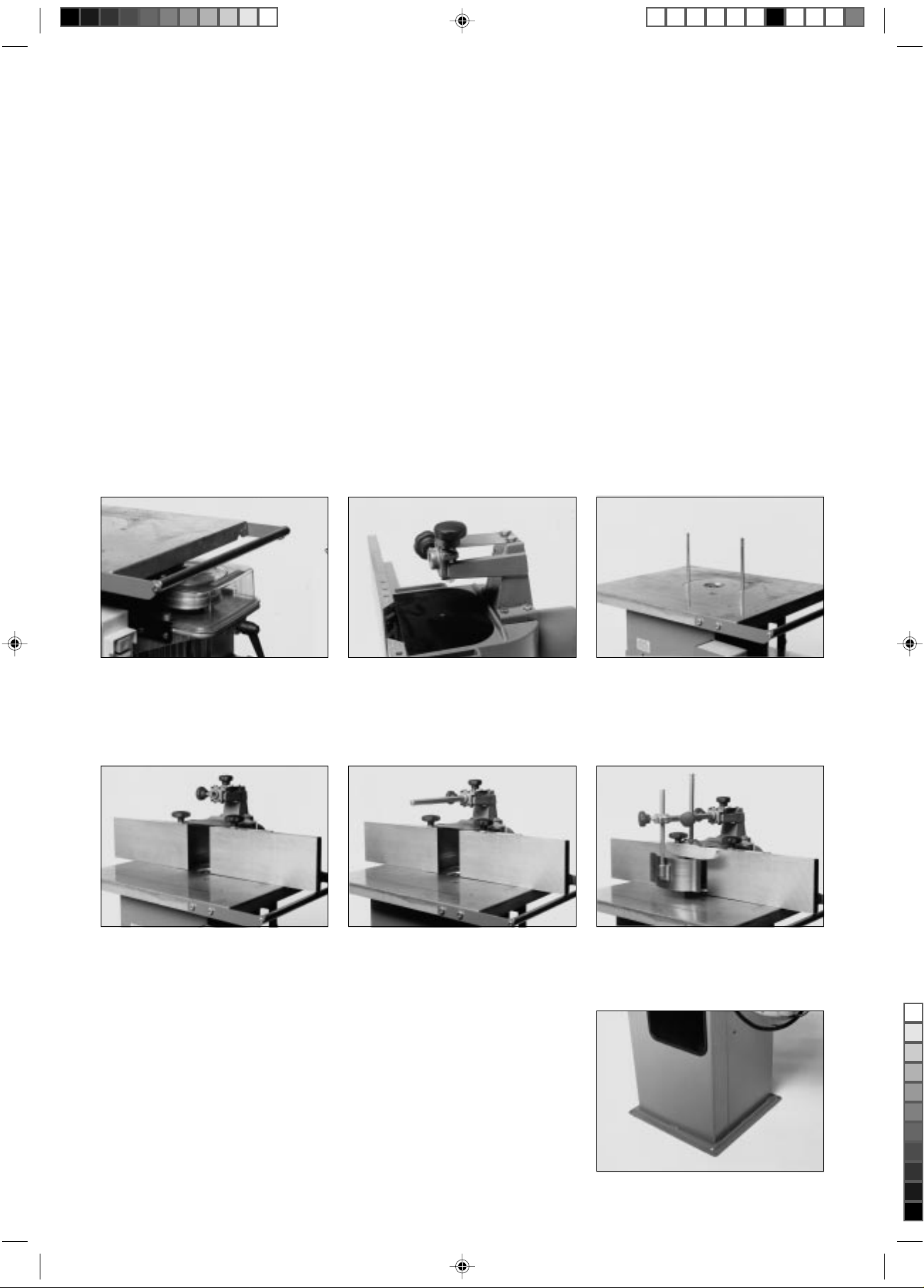
5 Final Assembly
Set table extension level with the table. Install cutter guard carrier on the fence.
Use 4 each
- hexagon head screw M 6x25
- hex. nut M 6 self-locking
Place fence on table and screw
starknobs onto stud bolts.
Slide hexagon bar into fence carrier
and lock with starknob screw.
6 Installation
Important!
This spindle moulder model TF 100 M must be anchored to the floor for
stability. A machine not anchored to the floor may fall over while in
operation.
Use suitable means for anchoring, e.g. anchoring bolts or expansion
anchors Ø 8 mm.
Screw both stud bolts into the tapped
bore holes of the table.
Install holddown shoe and spring on
hexagon bar.
3
Page 4
7 Commissioning
7.1 1-Phase Power Supply
This machine must be connected to an earthed outlet and operated on a residual current device (RCD) of 30 mA
capacity. Supply voltage required 230V ±5% 50 Hz. Protect circuit with a fuse 16 A time-lag. A supply line lead
cross section of min. 3 x 2.5 mm2 is required.
7.2 3-Phase Power Supply
A 5-wire (L1-L2-L3-N-Earth) supply system is required. Connect with the 16A CEE industrial type plug to an
earthed outlet equipped with a residual current device (RCD) of 30 mA capacity. Supply voltage required 400V
±5% 50 Hz. Protect circuit with 3 fuses 16 A time-lag. A supply line lead cross section of min. 5 x 1.5 mm2 is
required.
7.3 Direction Of Rotation
For machines with single-phase motor the direction of rotation is factory set. On machines with a three-phase
motor the direction of rotation must be checked after connection to the power supply. Start motor briefly. The
spindle, when viewed from the top, must turn counter-clockwise. To change the direction of rotation interchange
2 of the current conduction leads (black and/or brown). Do not connect the yellow-green earth lead to any of
the current conducting leads.
Note:
With a wrong direction of rotation there is danger of accident. Check direction of rotation carefully.
Have phases interchanged only by a qualified electrician!
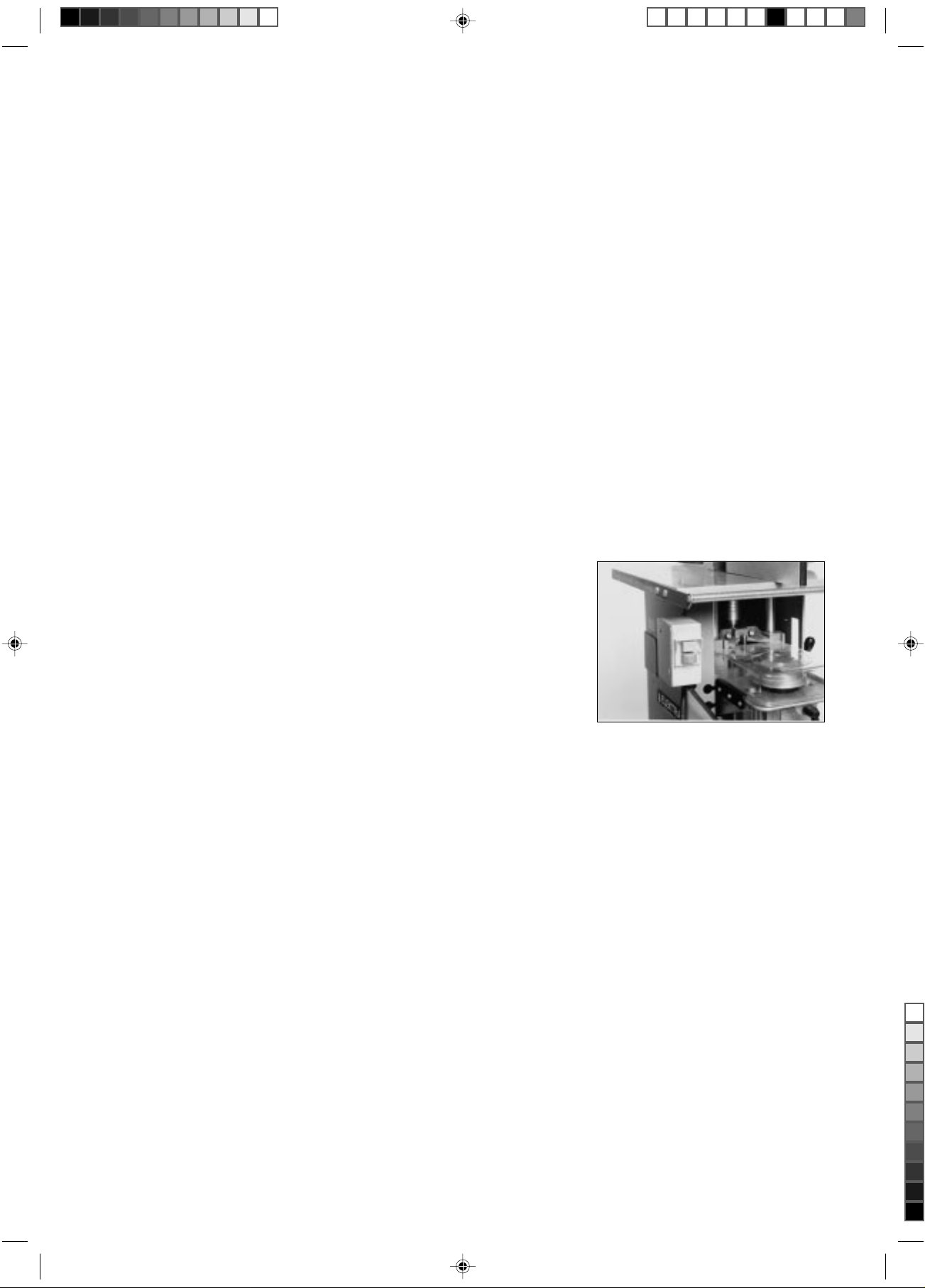
7.4 Switch
This spindle moulder is started by actuating the green push-button and
stopped by actuating the red button.
7.5 Overload Protection
In case of an overload the build-in motor protection relay switches the power off. Let motor cool off for approx.
10 minutes before starting again.
7.6 No-Voltage Release
The switch is equipped with a no-volt release solenoid (magnetic switch) to prevent start-up after a power failure.
It the machine is not connected to the power supply the switch does not engage. In the event of a power failure
the machine has to be restarted by switching ON again.
7.7 Dust Collection
This spindle moulder must be connected to a dust collector.
- The fine dust of beech or oak is classified as cancer-causing.
The dust collector this spindle moulder is to be connected to must provide for a minimum air flow rate of
16 m/sec at the machine's dust extraction outlet.
The dust extraction outlet's nominal diameter is 100 mm.
7.8 Dust Collector Automatic Start
The electrical installation must provide for automatic starting of the dust collector when the spindle moulder is
switched on, and for a 20 second switch-off delay after the spindle moulder is switched off.
4
Page 5
8 Safety Information
- Always follow the instructions in this manual.
- Use only tools approved for manual feed (BG-Test or similar).
- Never exceed the max. permissible tool speed.
- Follow the specific instructions supplied with the tool by the tool maker.
- Do not use tools of larger diameter than specified for this machine.
- Do not work stock with smaller or larger dimensions than specified in this manual.
- Always disconnect from power before servicing.
- Always let the spindle come to a complete stop before removing any obstructions.
- Fence, fence plates and cutter guard have to be set as required for the job on hand.
- Always feed strips and other small workpieces with a pushstick or pushblock.
- Select a suitable spindle speed (see section 11.0 of this manual).
- Persons under the age of 16 should not operate this machine.
- Ensure you know how to switch off the machine in an emergency.
- Always wear eye protection.
9 Workpiece Dimensions
- Workpieces shorter than 200 mm must not be worked on this spindle moulder unless a suitable feeding jig is
used for support.
- Support workpieces longer than 1000 mm with table extensions (optional accessory) or roller stands to keep
them from falling off the machine's table.
- The maximum workpiece width (for boards) should not exceed 500 mm.
10 Scope Of Application
- The Spindle Moulder model TF 100 M is designed for moulding workpieces of timber and/or timber derived
products, e.g. chip or particle board, fibre boards and plywood, either plain or laminated/faced with plastics.
- Moulding on endgrain, e.g. making tenons, requires a sliding carriage (optional accessory) for firm guiding.
- Set-in work should only be carried out with a table extension attached to one or both sides of the machine's table.
- Moulding of contoured workpieces is not permitted with this spindle moulder.
- Climb cutting operations are not permitted with this spindle moulder.
11 Tool Dimensions/Cutting Speeds
In order to reduce the risk of kickback the cutting speed of the tool used must be greater than 35 m/s.
- Moulding tools cannot safely be used at the lowest speed setting of 4000 min-1. This speed is intended for use
with brushes, wobble saws and similar tools.
- For a spindle speed of 6000 min-1 the tool must have a minimum diameter of 115 mm.
- For a spindle speed of 7500 min-1 the minimum tool diameter is 90 mm.
- At both spindle speeds suitable for moulding (6000 and 7500 min-1) the max. permissible tool diameter is
150 mm.
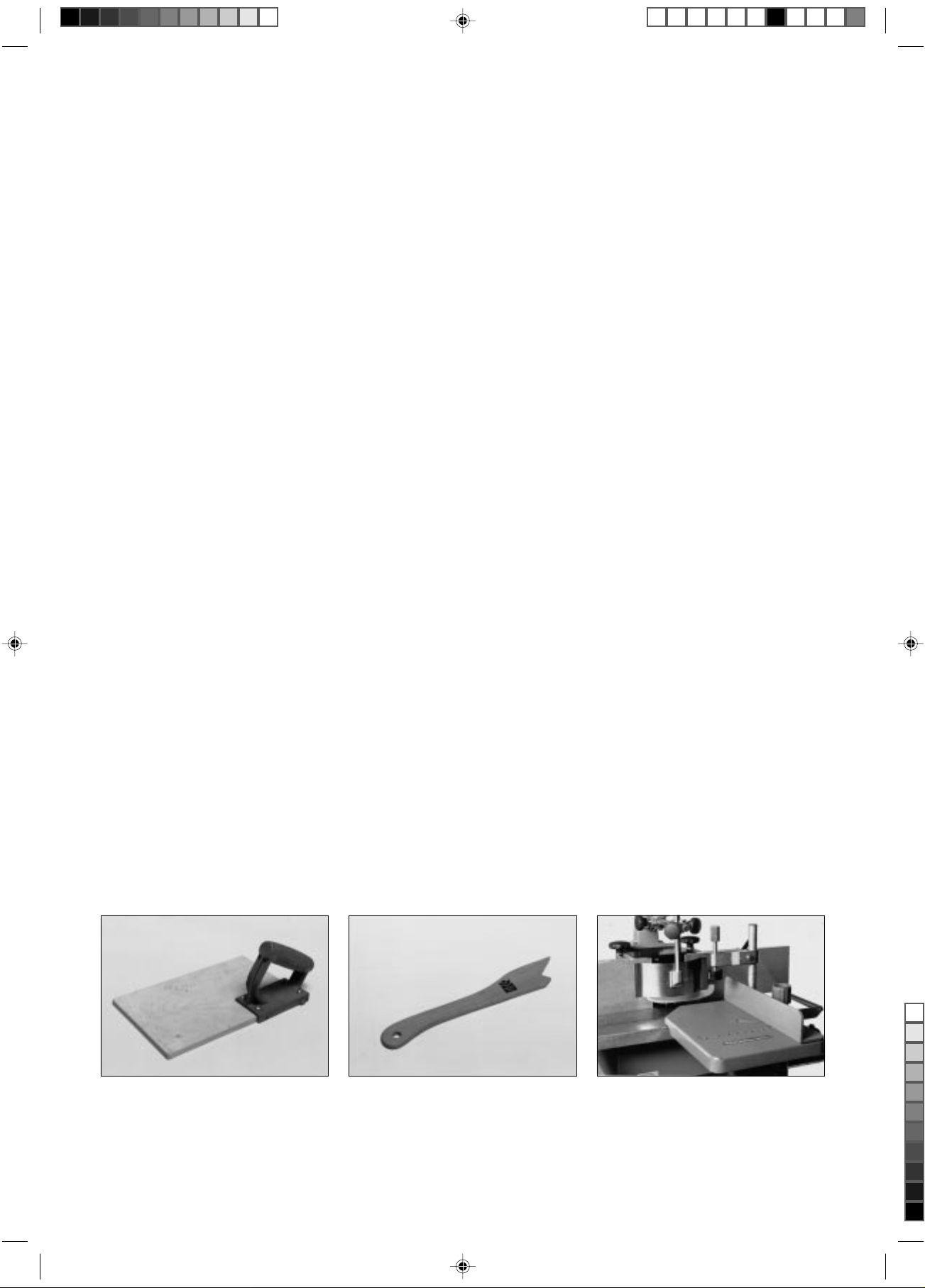
12 Jigs And Push Blocks
A pushblock is used to feed strips
held down by the safety cutter guard.
It should be made from 8-10 mm thick
plywood.
A pushstick is used to feed stock
which is held down only by the cutter
guard's pressure shoe.
5
Mould across end grain only with the
workpiece firmly supported in the sliding carriage. Very high risk of kickback and personal injury if no sliding
carriage is used.
Page 6

An auxiliary (or false) fence bridges
the gap between the two fence plates
to provide firm support and guiding for
small workpieces. Retracting the
fence, with the tool running, cuts
through the auxiliary fence.
Strips shorter than 200 mm must be held in user-made feeding jigs for
moulding.
13 Controls
13.1 Definitions
3
2
1
1 Spindle
2 Spacing collars
3 Spindle nut
4 Main frame
5 Handwheel for spindle vertical adjustment
9
8
7
6
5
4
6 Starting switch
7 Table
8 Fence plates
9 Pressure shoe
10 Fence
11 Spindle lock
10
11
13.2 Mounting A Tool
For mounting or removing a tool it is
recommended to remove the fence
from the table.
The tool is held by the spacing collars.
A rough height positioning on the
spindle is done by placing spacing
collars under the tool as required.
6
Place tool on spindle (mind direction
of rotation) and spacing collars on top
right up to the spindle thread. Then
screw on the spindle nut.
Page 7

13.3 Spindle Speed Setting/Changing
Remove the plastic cover to have
access.
13.4 Tool Height Setting
If the tool is only partially used and
needs to be lowered below the table,
remove the table rings before mounting it on the spindle.
Loosen the ratchet lever and place
belt on the desired step of the pulleys.
Available speeds are:
top = 4000 min
centre = 6000 min
lower = 7500 min
-1
-1
-1
Spindle vertical adjustment is
achieved by turning the handwheel
inside the main frame. Turn
- clockwise to raise
- counter-clockwise to lower
Tighten the belt and replace the plastic guard.
After a spindle height adjustment lock
in position by engaging the spindle
lock lever.
Caution!
Switch machine off and let tool come to a complete stop before making any adjustments.
13.5 Fence And Fence Plate Setting
AA
Loosen both starknobs (A) to move
the fence forward or backwards.
Loosen the starknobs (B) to reposition the fence plates.
BB
Caution!
Switch machine off and let tool come
to a complete stop before making any
adjustments.
7
Page 8

13.6 Cutter Guard Setting
C
D
E
Loosen starknob (C) and set holddown
shoe onto the workpiece.
Caution!
Switch machine off and let tool come to a complete stop before making any adjustments.
Adjust downward pressure with starknob (D).
After loosening starknob (E) set spring
guide against the workpiece.
14 Operation
14.1 Tools
This spindle moulder model TF 100 M must only be operated with tools having chip limitors for reduced kickback
and approved for manual feed, e.g. BG-TEST tools or equivalent.
14.2 Stock Prechecking
- Grown timber should be planed prior to any moulding operation.
- Do not work stock that is warped, bend or otherwise does not rest fully over its full length on the table and/or
against the fence plates.
14.3 Moulding Strips
- Mount tool as per section 13.2.
- Set/check spindle speed as per
section 13.3.
- Adjust spindle and fence as per
sections 13.4 and 13.5.
- Adjust cutter guard as per section
13.6 to accommodate the
workpiece.
- Start machine and feed the workpiece with a steady motion slowly
against the rotating tool.
14.4 Moulding Boards
- Mount tool as per section 13.2.
- Set/check spindle speed as per
section 13.3.
- Adjust spindle and fence as per
sections 13.4 and 13.5.
Caution!
Always feed with a pushstick if the workpiece width is less than 120 mm.
- Remove the cutter guard's pressure spring.
- Set holddlown shoe as described
in section 13.6.
Important!
Always use a pushblock to feed the
work when near the end.
- Start machine and feed the workpiece with a steady motion slowly
against the rotating tool.
8
Page 9

14.5 Making Tenons
Tenons and grooves in end grain must only be made with the workpiece firmly held and guided by the sliding
carriage TF 100, available as optional accessory.
To complete the tenon, turn workpiece over by 180° and make another
pass.
Place workpiece on the sliding carriage's table and secure with the clamping arm. Lower the holddown shoe
as much as possible to cover the
space between the fence plates above
Start machine. Feed work slowly and
with a steady motion against the rotating tool. When the pass is completed
pull the sliding carriage back to its
starting position.
the tool.
14.5 Set-In Work
Install table extension according to
the instructions provided. Set tool,
fence and guard as required.
Set the backstop as required. Start machine. Place workpiece on
15 Care And Maintenance
Always disconnect from power before servicing.
Danger of severe personal injury if machine is started unintentionally.
- Lubricate all moving parts regularly with a few drops of motor oil.
- Clean table and fence plates regularly, keep resin-free.
the table and against the backstop,
then push forward against the fence
into the rotating tool.
16 Electrical Wiring Diagrams
11.5 A
43 33 23 13 a
0 I
44 34 24 14 b
bl br gnge
Ha
U2
U1
Z1
Hi
Links
Z2
TF 100 M 1~230 V TF 100 M 3~400 V
230 V
L
N
PE
5.0 A
0 I
43 33 23 13 a
44
34 24 14
bl
br SW1
Links
400 V
b
gnge
L1
L2
L3
N
PE
9
Page 10

17 Spare Parts List TF 100 M
Pos. Description Dimension DIN Stock-no.
1 Table 139 001 7029
2 Guide bar 138 515 4697
3 Connecting bracket 149 202 4712
4 Guide frame 139 001 6901
5 Motor bracket 139 201 6941
6 Clamping piece-spindle lock 139 201 6950
7 Spindle lock shaft 139 501 6446
8 Grip handle 139 501 6969
9 Eye bolt M 12x80 444 614 101 6693
10 Threaded spindle 139 501 6470
11 Spacer bush 644 262 9070
12 Handwheel 101 412 9932
13 Spindle Ø30 mm 138 561 0005
14 3-step pulley, small 4Jx63 724 007 6521
15 Grooved ball bearing 6005 RS 710 001 6812
16 Bearing shell, upper 139 501 6888
17 Bearing shell, lower 139 501 6896
18 Grooved ball bearing 6204 RS 710 001 6820
19 Poly-V-belt 711 PS 4 723 307 2502
20 U-bolt M8 D8 615 901 6658
21 Spacing collar 25 Ø30x50x25 8837 148 509 9790
22 Spacing collar 10 Ø30x50x10 8837 148 509 9774
23 Spacing collar 8 Ø30x50x8 8837 148 509 9766
24 Spacing collar 5 Ø30x50x5 8837 148 509 9758
25 Spacing collar 16 Ø30x50x16 8837 148 509 9782
26 Spindle nut M 30x2 SW41 101 413 5215
27 3-step pulley, large 4Jx112 724 007 6513
28 Bracket-table extension 148 221 4610
29 Rod-table extension 148 521 4620
30 Pulley cover slide bracket, left 139 101 6840
31 Pulley cover slide bracket, right 139 100 6101
32 Pulley cover 139 100 6080
33 Main frame TF 100 101 421 4689
34 Table ring, large Ø170.2x15 139 001 7037
35 Table ring, small Ø111.5x15 139 001 7045
36 Fence 139 001 7053
37 Fence slide cover 139 100 6098
38 Fence plate 139 302 8919
40 Starknob M8 700 001 7730
41 Stud bolt M 8x160 663 101 7019
42 O-ring 46.3 x 2 763 201 9730
45 Thumb screw M 8x30 615 007 9800
7000 n.s. Cone bush for spindle 138 560 9775
n.s. = not shown in drawing
10
Page 11

U.K. Supplement to Operating Instructions for Elektra Beckum
TF 100 M Spindle Moulder
Please note the following supplementary information associated with this machine:
U.K. Legislation and Codes of Practice
When used industrially within the U.K. this machine falls under the scope of:
- Woodworking Machines Regulations 1974
- Use and Provision of Work Equipment Regulations 1992
We strongly advise you study and follow these regulations.
Section 7.1 1-Phase Power Supply
230 V motor. Although the motors supplied with this machine will run safely on a 13A domestic ring main, on
starting the machine a high current of very short duration is drawn, which could cause your 13A fuse to blow. If
this persists we recommend to have the machine connected to a 16A separate radial circuit. Ensure a suitably
sized fuse matching the motor is used.
This work should be undertaken only by a qualified electrician!
Wiring Instructions
Warning: This appliance must be earthed!
If the plug, fitted to the power cable supplied with the machine, has to be changed or replaced, connect the mains lead
conductors in accordance with the following colour code.
Single-phase motors (110/115/220/230/240 volts):
Yellow/green - Earth
Blue - Neutral
Brown - Live
Three-phase motors (220/380/400/415 volts):
Machines with a 3-phase motor are connected to power mains using a 5-pin industrial appliance-inlet/connector
according to
VDE 0623/BS 4343/IEC 309.
4-wire mains lead Yellow/green - Earth
Brown - Phase (L1)
Black - Phase (L2)
Blue - Phase (L3)
5-wire mains lead Yellow/green - Earth
Brown - Phase (L1)
Black - Phase (L2)
Black - Phase (L3)
Blue - Neutral
IF IN DOUBT - CONSULT A QUALIFIED ELECTRICIAN!
114950
Page 12

Page 13

Page 14

 Loading...