

Page 1

D
Betriebsanleitung
Separater Drahtvorschub
ENG
Operating Instructions
Separate Wire Feed Unit
Manual de instrucciones
Unidad de avance de alambre
separada
SDV 250 RC
SDV 250 E
Achtung! Lesen Sie die Betriebsanleitung vor der Installation und Inbetriebnahme des seperaten
Drahtvorschubes aufmerksam durch.
Important! Read and understand these instructions before installation and initial operation
of this Separate Wire Feed Unit.
¡Atención! Lea atentamente el Manual de instrucciones antes de la instalación y la puesta en marcha de la
unidad de avance de alambre separada.
115 110 1506 / D/GB / 1103 - 1.4
Page 2

Produkthaftung/Garantie
Nicht aufgeführte Arbeiten und Einsatzmöglichkeiten bedürfen der schriftlichen Genehmigung der Metabowerke
GmbH, Business Unit Elektra-beckum, Postfach 13 52, D-49703 Meppen.
Den Kaufbeleg bitte aufbewahren! Ein Anspruch auf Garantieleistungen besteht nur gegen Vorlage des Kaufbelegs. Die
Adresse Ihrer nächstgelegenen Werkvertretung finden Sie auf der hinteren Umschlagseite.
Bitte melden Sie sich mit Garantieansprüchen bei Ihrem Fachhändler.
Garantiearbeiten werden grundsätzlich durch uns oder von uns autorisierten Servicestellen durchgeführt.
Außerhalb der Garantiezeit können Sie Reparaturen durch entsprechende Fachfirmen ausführen lassen.
Bitte Reparaturrechnungen verwahren!
Inhalt
1 Anwendungsbereich
1.1 Systemzusammenstellungsmöglichkeiten
1.2 Technische Daten
2 Beschreibung
2.1 Bedienung- und Anschlußelemente des
SDV 250 RC
2.2 Bedienung- und Anschlußelemente des
SDV 250 E
3 Inbetriebnahme
3.1 Transport
3.2 Montage Drahtrolle
4 Störungsbeseitigung
5 Ersatzteilliste
6 Schaltplan
D
1 Anwendungsbereiche
Mit den separaten Drahtvorschüben hat man die Möglichkeit den Aktionsradius und die Flexibilität am Arbeitsplatz zu erweitern.
Die separaten Drahtvorschübe sind geeignet zum Verschweißen von Fe-Metallen und Aluminium gemäß der
Spezifikation der Schweißstromquelle.
1.1 Systemzusammenstellungsmöglichkeiten
SDV 250 E SDV 250 RC SDV 250 E-T SDV 250 RC-T
MIG/MAG 350 E –
MIG/MAG 300 SEC
MIG/MAG 350 SEC
MIG/MAG 400 SEC/W
MIG/MAG 500 SEC/W
MIG/MAG 300 SEC/X
MIG/MAG 350 SEC/X
MIG/MAG 400 SEC/WX
MIG/MAG 500 SEC/WX
SEK - W
SEK - WX
SEM - W
SEM - WX
1
1
1
1
1
1
1
1
1
1
1
1
W- Wasserkühlung
x-ohne internen Drahtvorschub
1
- Einsatz nur mittels Adapter (Bestell-Nr. 090 201 1285)
1.2 Technische Daten
SDV 250 E (-T) SDV 250 RC (-T)
Betriebsspannung Motor 28 V 28 V
Arbeitsspannung Steuerung - 9 V
Schaltstufen stufenlos stufenlos
Schutzart Kleinspannung Kleinspannung
Gewicht 605x270x410 605x270x410
Maße 26,5 kg 27,0 kg
Page 3
2 Beschreibung
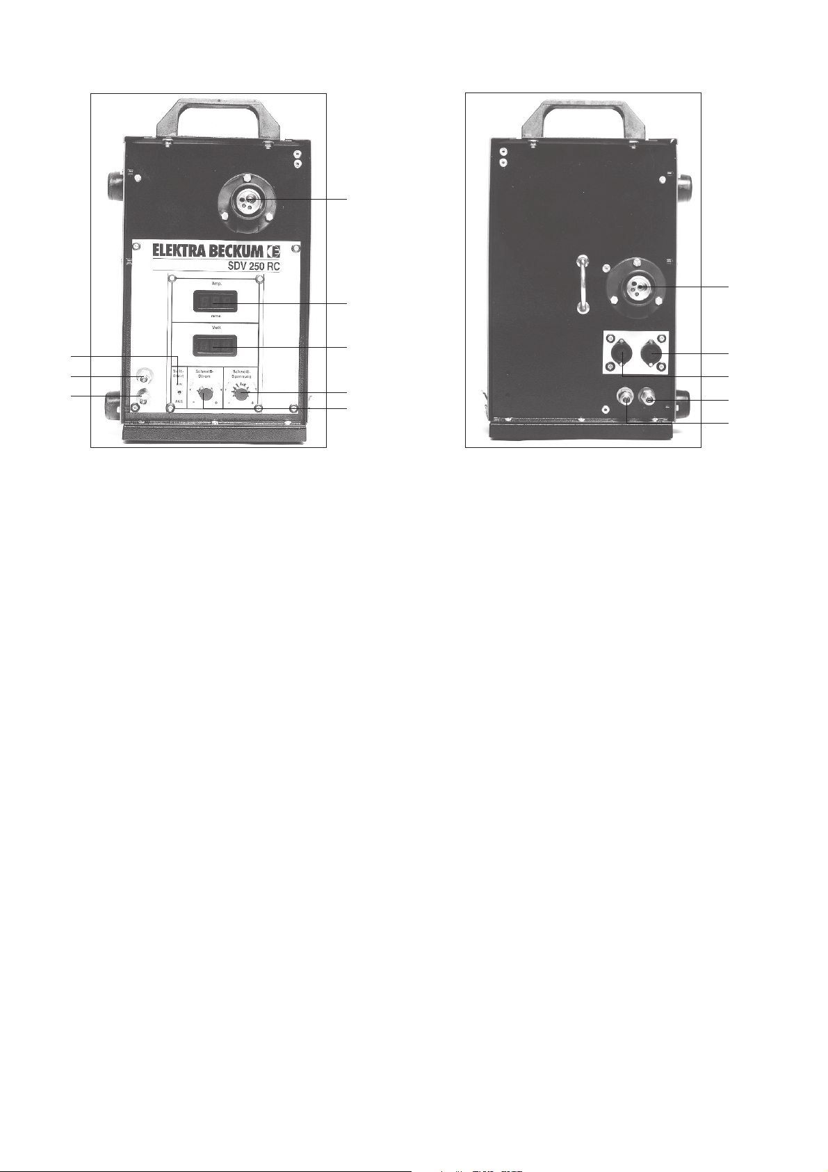
2.1 Bedienungs- und Anschlußelemente des SDV 250 RC
1
2
11
6
7
8
3
4
5
Bild 1
Front- u. Rückansicht
1 Zentralanschluß
2 Digitale Schweißstromanzeige (A) und momentane Drahtvorschubgeschwindigkeit m/min.
Im eingeschalteten Zustand zeigt das Schweißgerät die eingestellte momentane Drahtvorschubgeschwindigkeit in m/min. Beim Beginn des Schweißprozesses springt die Digitalanzeige um und
zeigt den eingeschalteten Schweißstrom (A) an.
3 Digitale Schweißspannungsanzeige V
4 Feinkorrektur der Schweißspannungsanzeige
Hiermit besteht die Möglichkeit, den automatisch errechneten optimalen Drahtvorschub zu beeinflußen. Es
kann die Einbrandtiefe nach + und - (Lang- oder Kurz-Lichtbogen) korrigiert werden und vor allem die
Feinabstimmung bei verschiedenen Positionsschweißung oder entsprechender Materialspezifikation. Die
eingestellte Schweißspannungsanzeige wird digital (3) angezeigt.
9
10
12
13
5 Stufenlose Schweißstromeinstellung
Hiermit wird stufenlos der Schweißstrom von minimal bis maximal eingestellt. Entsprechend der Einstellung des Drahtsortenwahlschalters (Pos. 14 - Schweißgerät) wird automatisch der Drahtvorschub durch
den Leistungssteller immer im optimalen Bereich gewährleistet. Feinkorrektur ist durch Pos. 4 möglich
(Lang- oder Kurzlichtbogen).
6 Softstartautomatik EIN/AUS
Solange kein Kurzschluß stattfindet, wird der Zusatzwerkstoff sehr langsam gefördert, um einen zu langen
Drahtauslauf am Brennerkopf zu verhindern. Wenn gezündet wird, läuft automatisch entsprechend des
eingestellten Schweißstroms die entsprechende Drahtgeschindigkeit. Beim Wechseln des Zusatzwerkstoffes (Drahtrolle) sollte die Softstartautomatik auf "AUS" gestellt sein, ebenfalls beim Punktschweißen.
7+8/
12+13 Kühlwasseranschluß
9 Anschluß Steuerleitung - Platine
10 Anschluß Steuerleitung - Motor
11 Zentralanschluß - Zwischenschlauchpaket
Page 4
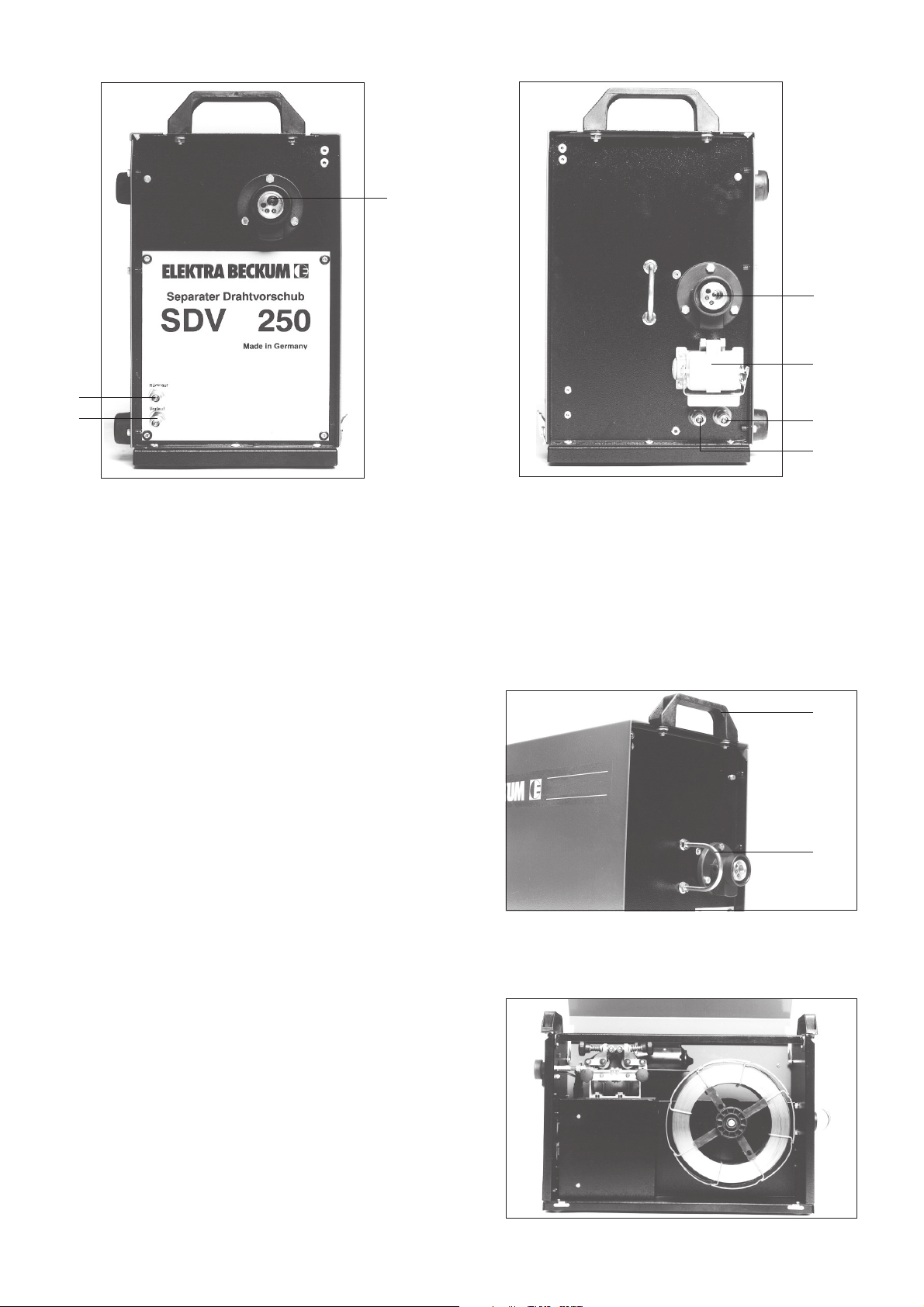
2.2 Bedienungs- und Anschlußelemente des SDV 250 E
1
2
3
1 Zentralanschluß
5
4
6
7
Bild 2
Front- u. Rückansicht
2/3/6/7 Kühlwasseranschluß
4 Anschluß Steuerleitung - Motor
5 Zentralanschluß - Zwischenschlauchpaket
3 Inbetriebnahme
3.1 Transport
Der Separate Drahtvorschub kann mit einem Aufnahmewagen ausgerüstet werden, welcher drehbar am
Schweißgerät angebracht werden kann.
Zusätzliche Transportgriffe (1) und Kranhalteöse (2)
sichert vielseitige Transportmöglichkeiten zu.
1
2
Bild 3
Ansicht - Transporteinrichtungen
3.2 Montage Drahtrolle
Die Schweißdrahtrolle so auf den Spulendorn setzen,
daß das Drahtende nach links, also entgegengesetzt
des Uhrzeigersinnes abläuft.
Auf den Spulendorn befindet sich eine Bremse die
durch eine Imbusschraube eingestellt werden kann.
Die Bremse sollte so eingestellt werden, daß beim
Schweißprozeßende die Drahtrolle nicht nachläuft, um
somit ein Lockern der Drahtspulung zu verhindern.
Bild 4
Gesamtansicht Drahtvorschubeinheit
Page 5
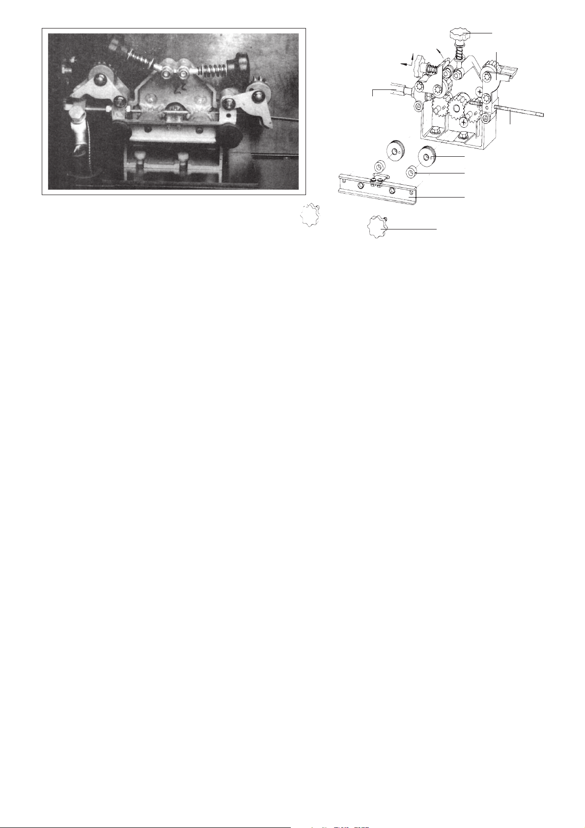
Brenneranschluß
Sterngriff
Rollenhalter
Führungs-
spirale
Drahtführungsrolle
Distanzring
Bild 5 - Geöffneter Drahtvorschub mit Explosionszeichnung
Achsenhalter
Sterngriffschraube
Andruckrollen mittels Sterngriffe lösen und aufklappen. Die Drahtführungsrollen sind werkseitig für die Verwendung von 1,2/1,6 mm Ø Schweißdraht eingerichtet. (Bei Einsatz von 0,8/1,0 Schweißdraht müssen die Drahtführungsrollen abgenommen und gedreht werden.) Den entgrateten Draht durch die Führungsspirale, über die
hintere Vorschubrolle, durch das Führungsrohr und über die vordere Vorschubrolle in den Zentralanschluß führen.
Andruckrollen zuklappen und mit den Sterngriffen spannen. Achten Sie bitte darauf, daß der Anpreßdruck der
vorderen Andruckrolle ein wenig stärker eingestellt wird als an der hinteren Andruckrolle. Bei Nichtbeachtung ist
kein optimaler Drahtvorschub gewährleistet.
Gasdüse am Brennerhals durch Rechtsdrehen und Stromdüse durch Linksdrehung abschrauben und Hauptschalter ( Pos.17 - Schweißgerät) einschalten. Brennerschalter bei geringem Drahtvorschub solange betätigen,
bis ein Drahtaustritt von ca. 2 cm vorhanden ist.
Gas- und Stromdüse in entgegengesetzter Drehrichtung wieder fest anschrauben.
Beachten Sie bitte, daß die Geräte serienmäßig für die Verwendung eines Schweißdrahtes von 1,2 mm
Durchmesser ausgelegt sind. Bei Benutzung eines anderen Durchmessers müssen die Stromdüse und die
Führungsspirale entsprechend ausgewechselt werden.
Page 6

4 Störungsbeseitigung
Störung Beseitigung
- Unregelmäßiger Drahtvorschub
- Spröde oder poröse Schweißnaht - Anschlüsse überprüfen
Störungsursache
- Falscher Anpressdruck am Rollenvorschub
- Drahtführung am Vorschub-Motor
nicht in einer Linie
- Führungsspirale verstopft, oder für
Drahtstärke nicht passend
- Schlecht gespulter Draht oder
Draht-Kreuzungen
- Verrosteter Draht oder schlechte
Qualität
- Zu stark angezogene Dornbremse
- Vorschubrollen verschmutzt oder
abgenutzt bzw. nicht passend für
Drahtstärke
- Gasschlauchanschlüsse undicht
- Leere Gasflaschen
- Gashahn geschlossen
- Druckminderer defekt
- Gasdüse am Brenner oder
Schlauchpaket verstopft
- Zugluft an der Schweißstelle
- Schlechte Drahtqualität, oder
- Ungeeignetes Schutzgas
- Richtigen Druck einstellen
- Vorschubrolle und Drahtführung in
Linie bringen
- Überprüfen, evtl. wechseln
- Drahtrolle tauschen
- Drahtrolle tauschen, Führungsspirale
reinigen bzw. tauschen
- Dornbremse lösen
- Vorschubrolle reinigen bzw. wechseln
- Gasflasche tauschen
- Gashahn offnen
- Druckminderer überprüfen
- Gasdüse reinigen und Brenner einsprühen
- Paket ausblasen
- Schweißstelle abschirmen
- Rost, Fett oder Lackschicht entfernen
- Neuer Schweißdraht, geeignetes
Schutzgas verwenden, z.B. Mischgas
- Ständiger Gasaustritt - Magnetventil defekt
- Fremdkörper im Magnetventil
- Kein Drahtvorschub - Brennerschalter oder Steuerleitung
im Brennerpaket defekt
- Steuerplatine defekt
- Kein Schweißstrom bei normal
funktionierendem Drahtvorschub
- Beim Berühren des Werkstückes
mit der Gasdüse entsteht Lichtbogen
- Brenner wird zu heiß - Stromdüse zu groß oder lose
- Massekabel gibt keinen richtigen
Kontakt
- Kurzsschluß zwischen Strom- und
Gasdüse
- Wasserkreislauf gestört
- Magnetventil reinigen bzw. tauschen
im Schweißgerät
- Brennschalter und Steuerleitung überprüfen
- Steuerplatine tauschen
- Massekabel auf richtigen Kontakt prüfen (Schweißgerät)
- Gasdüse und Brennerhals reinigen
und mit Pistolensspray einsprühen
- Passende Stromdüse für Drahtstärke
einsetzen, Düse festschrauben
- Pumpe defekt, Kühlwasser nachfüllen (Schweißgerät)
Page 7
Ersatzteilliste
Artikel-Nr. Bezeichnung SDV SDV SDV SDV
250 E 250 RC 250 E-T 250 RC-T
824 103 3466 Durchführungstülle ●●
634 106 2550 Kunststoffrosette ●●●●
771 015 1002 Schnellkupplung mit Mutter und Schlauchtülle ●●●●
785 001 2088 Gewebedruckschlauch RD. 6 mm ●●●●
781 111 6402 Schlauchschelle ●●●●
821 514 1358 Einbaukupplung 4-polig
821 510 1330 Sockelgehäuse mit Buchseneinsatz ●●
615 901 6658 Bügelschraube M8 ●●●●
132 703 3430 Zentralanschluß ●●●●
132 708 6010 Kapillarrohr für Drahtdurchmesser bis 1,6 mm ●●●●
132 110 1522 Isolierscheibe Rd. 20x6 ●●●●
132 110 1530 Isolierscheibe Rd. 20x4 ●●●●
810 614 4215 Platine für Fernregelung ●
801 109 2064 Vorschubmotor ●●
132 500 0259 Stirnrad mit Nabe (Stahl) ●●
132 100 0378 Stirnrad ohne Nabe (Kunststoff) ●●●●
132 500 9752 Stirnrad ohne Nabe (Stahl) ●●●●
132 500 0232 Drahtführungsrolle gehärtet ●●●●
132 001 6670 Rollenhalter ●●●●
132 500 0240 Drahtandruckrolle gehärtet ●●●●
824 107 0868 Durchführungstülle ●●●●
132 107 3880 Spulendorn komplett ●●●●
801 119 4509 Vorschubmotor ●●
132 541 9578 Stirnrad mit Nabe ●●
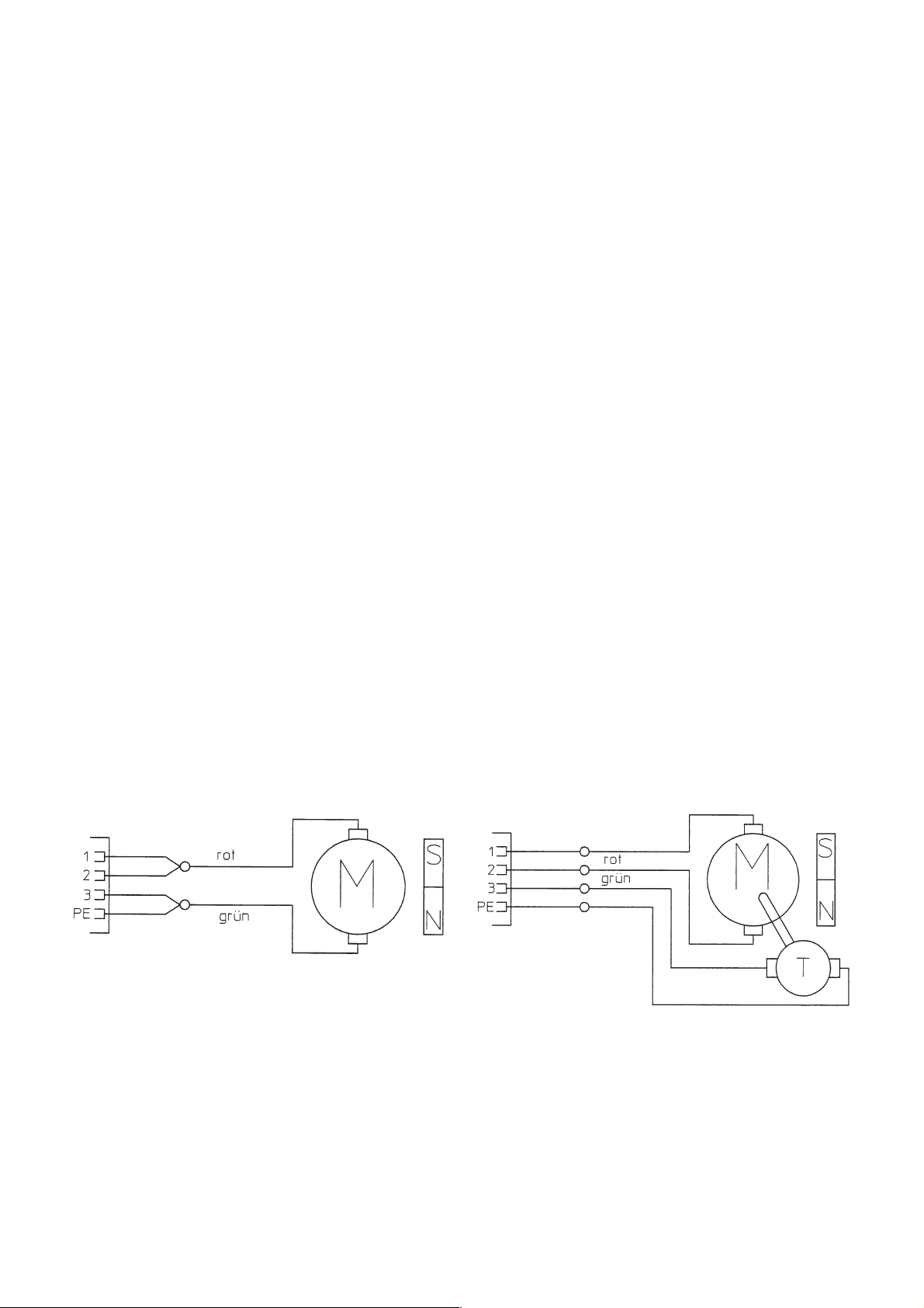
Schaltpläne
SDV 250 E
DRAHTVORSCHUBMOTOR
SDV 250 E - T
DRAHTVORSCHUBMOTOR
Page 8
SDV 250 RC
SDV 250 RC - T
DRAHTVORSCHUBMOTOR
DRAHTVORSCHUBMOTOR
Page 9

User Responsibility
Any other use requires the written consent of Metabo GmbH, Business Unit Elektra Beckum, P.O.Box 1352, D49703 Meppen, Germany. Retain proof of purchase! You are only entitled to claim warranty against proof of
purchase. Please see back cover for manufacturer representative's address nearest you.This machine will perform
in conformity with the description contained in the instructions provided. This machine must be checked
periodically. Defective equipment (including service leads) should not be used. Parts that are broken, missing,
plainly worn, distorted or contaminated, should be replaced immediately. Should such repair or replacement
become necessary, it is recommended that such repairs are carried out by qualified persons approved by the
equipment manufacturer or its representative. This machine or any of its parts should not be altered or changed
from standard specifications. The user of this machine shall have the sole responsibility for any malfunction which
results from improper repair by anyone other than qualified persons approved by the equipment manufacturer or
its representatives.
Contents
1 Scope Of Application
1.1 System Component Combinations
1.2 Specifications
2 Description
2.1 SDV 250 RC Controls
2.2 SDV 250 E Controls
3 General Instructions For Start-Up
3.1 Transportation
3.2 Installing The Wire Spool
4 Trouble Shooting
5 Trouble Shooting
5 Spare Parts List
6 Wiring Diagram
ENG
1 Scope Of Application
A Separate Wire Feed Unit offers a greater range of action and more flexibility in welding operations over a
welding power source with intregated wire feed only, as the maximum length of the torch leads is rather limited
for many welding operations.
The ELEKTRA BECKUM Separate Wire Feed Units are suitable for welding ferrous metals and aluminium as
specified for the welding power source.
1.1 System Component Combinations
SDV 250 E SDV 250 RC SDV 250 E-T SDV 250 RC-T
MIG/MAG 350 E –
MIG/MAG 300 SEC
MIG/MAG 350 SEC
MIG/MAG 400 SEC/W
MIG/MAG 500 SEC/W
MIG/MAG 300 SEC/X
MIG/MAG 350 SEC/X
MIG/MAG 400 SEC/WX
MIG/MAG 500 SEC/WX
SEK - W
SEK - WX
SEM - W
SEM - WX
1
1
1
1
1
1
1
1
1
1
1
1
W- water cooled torch
x-machine without intregated wire feed
1
- requires adaptor to operate (stock-no. 090 201 1285)
1.2 Technical Specifications
SDV 250 E (-T) SDV 250 RC (-T)
Voltage motor 28 V 28 V
Voltage electronic controls - 9 V
Range setting stepless stepless
Protection class extra-low voltage extra-low voltage
Dimensions 605x270x410 605x270x410
Weight 26.5 kg 27.0 kg
Page 10

2Description
2.1 SDV 250 RC Controls
1
11
2
6
7
8
3
4
5
1 Euro-Connector for MIG Welding Gun Leads
2 Digital Welding Current Display (A) and actual Wire Feed Speed m/min.
While the welding power source is switched on the current wire feed speed is displayed in meters per
minute. When starting the welding operation, the display changes to show the selected welding current in
amps.
3 Digital Welding Voltage Display (V)
4 Welding Voltage Fine Tuning
Adjusts the automatically set welding voltage. The weld penetration can be corrected to both + and - (long
or short arc), but more important the welding characteristics can be fine tuned for different welding positions
or material specifications. The currently selected welding voltage is displayed in the digital display [3].
9
10
12
13
Pic. 1
Front and rear view
5 Stepless Welding Current Setting
Sets the welding current steplessly from minimum to maximum. According to the setting of the electrode
wire selector [14] of the welding power source the machine's electronic controls keep the wire feed speed
within an optimal range. If required the wire feed speed can be adjusted with potentiometer [4].
6 Automatic Soft Start ON/OFF
While the arc has not yet ignited the filler material is fed very slowly to prevent excessive wire runout at the
torch. When the arc starts the wire feed speed is automatically increased as required by the selected
welding current. When changing the electrode wire or operating in spotweld mode, the automatic soft start
should be set of OFF.
7/8 &
12/13 Torch Coolant Couplings
9 Socket for Electronic Control Leads
10 Socket for Motor Leads
11 Euro-Connector for Torch Lead Extension
Page 11

2.2 SDV 250 E Controls
1
2
3
1 Euro-Connector for MIG Welding Gun Leads
5
4
6
7
Pic. 2
Front and rear view
2/3/6/7 Torch Coolant Couplings
4 Socket for Motor Leads
5 Euro-Connector for Torch Lead Extension
3 General Instructions for Start-Up
3.1 Transportation
The Separate Wire Feed Unit can be fitted with a
rotating mount to install it on top of the welding
machine. Handles [1] and jack rings [2] provide for
easy transportation.
1
2
Pic. 3
View of transport facilities
3.2 Installing the Wire Spool
Place wire spool onto spool carrier so that wire runs
off clockwise.
The spool carrier is equipped with a brake, which can
be adjusted by means of a hex. socket head screw. Set
brake so that wire spool does not idle after wire feed is
switched off, to prevent the wire from coming loose and
falling off the spool.
Pic. 4
View of wire feed unit
Page 12

Torch coupling
Starknob screw
Gear bracket
Spiral guide tube
Feed roller
Spacer
Pic. 5 - Opened wire feed and exploded view drawing
Shaft bracket
Loosen starknob screws and open gear brackets. The feed rollers are factory installed for use with 1.2/1.4 mm wire
(for 0.8/1.0 mm wire the feed rollers have to be reversed on the shaft). Insert wire into spiral guide tube, place over
feed roller into guide tube of shaft bracket, then across the second feed roller into the Euro-connector. Close gear
brackets and tighten starknob screws, giving sligthly more pressure to the feed roller feeding into the Euroconnector
to ensure a smooth wire feed.
Remove gas shroud by turning clockwise and contact tip by turning counter-clockwise. Set Mains Switch ([17] of
welding power source) to ON and activate the torch's trigger switch until the wire portrudes approximately
2 cms from the torch. Re-install contact tip and gas shroud.
Please not that all models are factory-set for use with 1.2 mm electrode wire. If wire of a different diameter is used
the contact tip and steel liner have to be changed to match the wire diameter.
Page 13

4 Fault Remedy
Fault Remedy
- Irregular wire feed
- Brittle or porous welding seam - Check fittings
- Constant gas flow - Magnetic valve defective or dirty - Check, clean or replace
Cause
- Incorrect tension of tension roller
- Pilot groove of feed roller and intake
nozzle not aligned
- Liner clogged or not correct size for
wire
- Wire spooled irregularly, rusty or of
inferior quality
- Wire spool carrier brake too tight
- Feed rollers dirty of worn, groove
not matching wire size
- Gas line fittings not tight
- Gas cylinder empty
- Gas cylinder valve closed
- Pressure regulator not working
- Magnetic valve not working
- Gas shroud or line in lead ass'y
clogged
- Air draft at welding seam
- Workpiece not clean
- Wire of inferior quality or unsuitable
gas
- Adjust tension
- Align
- Check and/or change
- Change spool, clean or change liner
- Loosen
- Clean or replace
- Replace cylinder
- Open valve
- Check
- Check power at solenoid
- Clean shroud and spray, blow out gas
line
- Protect from gas or increase gas flow
- Remove rust, grease, paint
- Change wire, use suitable gas
- No wire feed - Trigger switch or leads in lead ass'y
defective
- PCB defective
- Fine-wire fuse of PCB defective
- No welding current with normal
working wire feed
- Arcing when gas shroud
touches workpiece
- Torch becomes excessively hot
- Mains contactor defective
- Power control unit defective
- Earth cable not conducting
- Short-circuit between contact tip
and gas shroud
- Contact tip loose or too large for
wire diameter
- Low coolant level
- Defective coolant pump
- Check, replace if necessary
- Replace
- Replace with fuse 2 A time-lag
- Check, replace
- Check, replace
- Correct
- Clean shroud, treat with anti-clogging
spray or nozzle dip
- Tighten tip, replace with correct size
tip
- Top off coolant
- Repair or replace
Page 14

5 Spare Parts List
Stock-no. Description SDV SDV SDV SDV
250 E 250 RC 250 E-T 250 RC-T
824 103 3466 Wire protecting sleeve ●●
634 106 2550 Plastic anchor plate ●●●●
771 015 1002 Quick coupling with nut & hose sterm ●●●●
785 001 2088 Nylon braided hose Ø 6 mm ●●●●
781 111 6402 Hose clamp ●●●●
821 514 1358 Panel coupling, 4-pole
821 510 1330 Base housing with receptacle ●●
615 901 6658 U-Bolt M8 ●●●●
132 703 3430 Euro-connector ●●●●
132 708 6010 Capillary Tube up to Ø 1.6 mm ●●●●
132 110 1522 Insulating washer Ø 20 x 6 ●●●●
132 110 1530 Insulating washer Ø 20 x 4 ●●●●
810 614 4215 Remonte Control PCB ●
801 109 2064 Wire feed motor ●●
132 500 0259 Drive cog with hub, steel ●●
132 100 0378 Drive cog w/o hub, plastic ●●●●
132 500 9752 Drive cog w/o hub, steel ●●●●
132 500 0232 Feed roller, hardened ●●●●
132 001 6670 Gear bracket ●●●●
132 500 0240 Pressure roller, hardened ●●●●
824 107 0868 Wire protecting sleeve ●●●●
132 107 3880 Spool carrier ass'y ●●●●
801 119 4509 Wire feed motor ●●
132 541 9578 Spur-wheel ●●
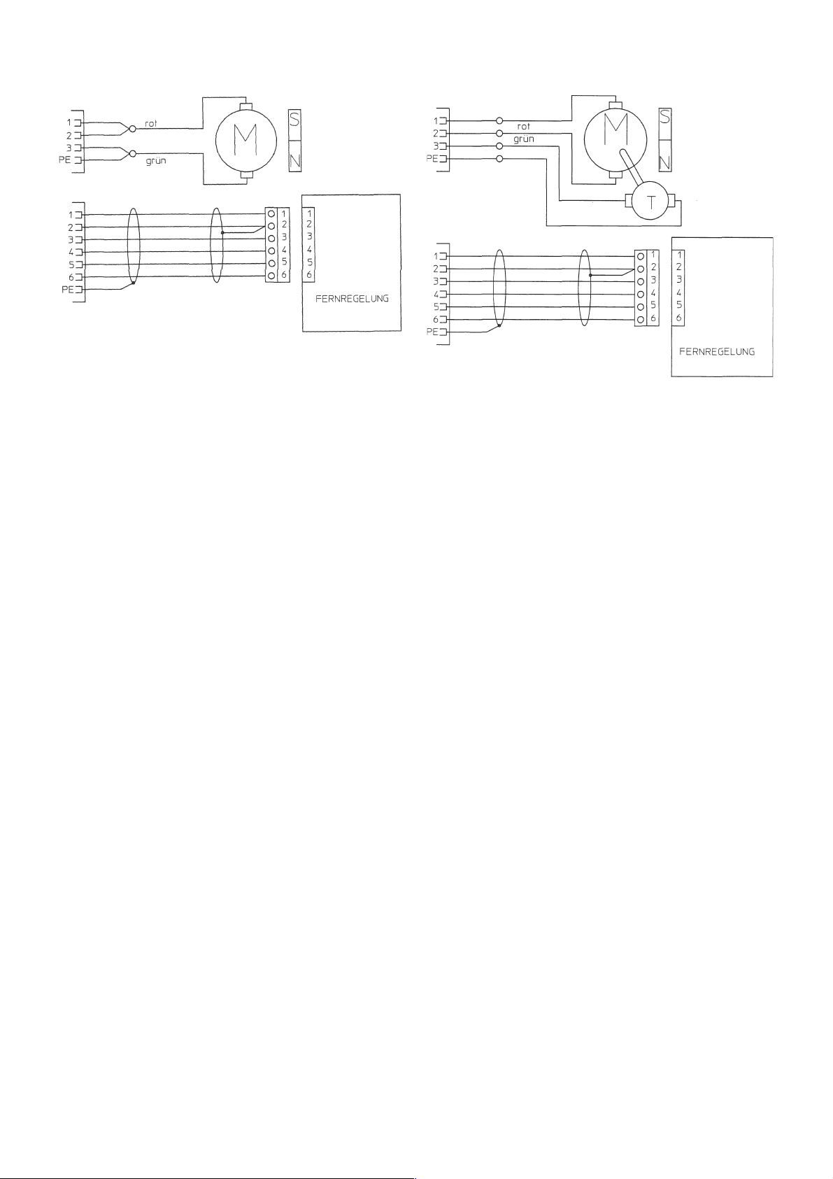
6 Wiring Diagram
red
green
SDV 250 E
Wire feed motor
SDV 250 E - T
Wire feed motor
red
green
Page 15

SDV 250 RC
SDV 250 RC - T
Wire feed motor
red
green
Wire feed motor
red
green
Control lead
Control lead
Page 16

ES
Responsabilidad de producto/garantía
Los trabajos y las posibilidades de aplicación no especificados precisan una autorización escrita de la empresa
Metabowerke GmbH, Business Unit Elektra-beckum, Postfach 13 52, D-49703 Meppen.
¡Conserve el comprobante de compra! Solo tendrá derecho a la prestación de garantía mediante presentación del comprobante
de compra. La dirección de la representación más cercana a Ud. podrá verla en la última página de cubierta.
Póngase en contacto con su proveedor en caso de derecho de garantía.
En principio, los trabajos bajo garantía serán llevados a cabo por nuestra empresa, o bien por los servicios técnicos
que autoricemos para ello.
Una vez fuera del período de garantía, puede permitir que las reparaciones sean realizadas por las empresas
especializadas que corresponda.
¡Guarde las facturas de reparación!
Indice
1 Campo de aplicación
1.1 Combinaciones posibles del sistema
1.2 Especificaciones técnicas
2 Descripción
2.1 Elementos de mando y conexión del
SDV 250 RC
3 Puesta en servicio
3.1 Transporte
3.2 Montaje del rodillo de alambre
4 Reparación de averías
5 Lista de repuestos
6 Esquema de contactos
2.2 Elementos de mando y conexión del
SDV 250 E
1 Ambitos de aplicación
Con las unidades de avance de alambre separadas se tiene la posibilidad de ampliar el radio de acción y la
flexibilidad del puesto de trabajo.
Las unidades de avance de alambre separadas son ideales para soldar metales ferrosos y aluminio conforme a
la especificación de la fuente de corriente para soldadura.
1.1 Combinaciones posibles del sistema
SDV 250 E SDV 250 RC SDV 250 E-T SDV 250 RC-T
MIG/MAG 350 E –
MIG/MAG 300 SEC
MIG/MAG 350 SEC
MIG/MAG 400 SEC/W
MIG/MAG 500 SEC/W
MIG/MAG 300 SEC/X
MIG/MAG 350 SEC/X
MIG/MAG 400 SEC/WX
MIG/MAG 500 SEC/WX
SEK - W
SEK - WX
SEM - W
SEM - WX
1
1
1
1
1
1
1
1
1
1
1
1
W- refrigeración de agua
x-sin avance de alambre interno
1
- Empleo solo con el adaptador (N° de pedido 090 201 1285)
1.2 Especificaciones técnicas
SDV 250 E (-T) SDV 250 RC (-T)
Tensión de servicio, motor 28 V 28 V
Tensión de trabajo, mando - 9 V
Escalones de conmutación sin escalonamientos sin escalonamientos
Tipo de protección baja tensión baja tensión
Peso 605x270x410 605x270x410
Medidas 26,5 kg 27,0 kg
Page 17

2 Descripción
2.1 Elementos de mando y conexión del SDV 250 RC
1
2
11
6
7
8
3
4
5
Fig. 1
Vista de frente y de fondo
1 Conexión central
2 Indicación digital de corriente de soldadura (A) y velocidad momentánea de avance de alambre m/
min.
En estado conectado muestra la soldadora la velodidad momentánea ajustada para el avance de alambre
en m/min. Al comenzar el proceso de soldadura salta la indicación digital y muestra la corriente de
soldadura conectada (A).
3 Indicación digital de tensión de soldadura V
4 Corrección en precisión de la indicación de tensión de soldadura
Con ello existe la posibilidad de influir en el avance de alambre calculado automáticamente de forma
óptima. Puede corregirse la profundidad de penetración en + y - (arco de soldadura largo o corto) y, sobre
todo, el ajuste fino de las diferentes posiciones de soldadura o de las especificaciones de material
correspondientes. La indicación de tensión de soldadura ajustada es mostrada digitalmente (3).
9
10
12
13
5 Ajuste sin escalonamientos de la corriente de soldadura
Aquí se ajusta sin escalonamientos la corriente de soldadura desde el máximo hasta el mínimo. De acuerdo
a la posición del interruptor del avance de alambre (Pos. 14 - soldadora) se garantiza el avance automático
del alambre por medio del regulador de potencia siempre en el sector óptimo. Es posible realizar una
corrección fina mediante la posición 4 (arco de soldadura largo o corto).
6 Automático de arranque suave CON./DES.
Mientras no tenga lugar algún cortocircuito es requerido muy lentamente el material de aportación, para
evitar un derrame largo de alambre en la cabeza del soplete. Al encender corre automáticamente la
velodidad del alambre correspondientemente a la corriente de soldadura ajustada. Al cambiar el material
de aporte (rollo de alambre), el automático de arranque suave debe estar ajustado en "DES.", igualmente
en la soldadura por puntos.
7+8/
12+13 Conexión de agua de refrigeración
9 Conexión conductor de mando - Platina
10 Conexión conductor de mando - Motor
11 Conexión central - Paquete de manguera intermedia
Page 18

2.2 Elementos de mando y conexión del SDV 250 E
1
2
3
1 Conexión central
5
4
6
7
Fig. 2
Vista de frente y de fondo
2/3/6/7 Conexión de agua de refrigeración
4 Conexión conductor de mando - Motor
5 Conexión central - Paquete de manguera intermedia
3 Puesta en servicio
3.1 Transporte
La unidad de avance de alambre separada puede
equiparse con un carro de asiento que pueda ser
colocado en la soldadora en forma giratoria.
Empuñaduras adicionales de transporte (1) y ojales
para sujeción en grúa (2) garantizan múltiples
posibilidades de transporte.
1
2
Fig. 3
Vista - Dispositivos de transporte
3.2 Montaje del rodillo de alambre
Orientar el rodillo de alambre de soldadura con respecto
al espigón de la bobina de forma tal que el extremo de
alambre corra hacia la izquierda, o sea, en sentido
contrario al reloj.
Sobre el mandril hay un freno que puede fijarse mediante
un tornillo Allen. El freno debería estar ajustado de tal
manera que al finalizar el proceso de soldadura, el
rodillo de alambre no marche en inercia, evitando de
este modo que se afloje el bobinado del alambre.
Fig. 4
Vista general, unidad de avance de alambre
Page 19

Empuñadura
estrellada
Sujetador de
rodillo
Conexión de
soplete
Rodillo guía de
alambre
Anillo
distanciador
Fig 5 - Avance de alambre abierto con representación en explosión
Sujetador de
ejes
Tornillo de empuñadura
estrellada
Suelte los rodillos de alimentación mediante empuñaduras en estrella y ábralos. Los rodillos guía del alambre han
sido diseñados de fábrica para la utilización de alambre de soldadura de 1,2/1,6 mm Ø. (Al emplear alambre de
soldadura de 0,8/1,0 deben quitarse y voltearse los rodillos guía de alambre.) Conduzca el cable desbarbado
mediante la espiral guía por encima del rodillo de alambre trasero, a través del tubo guía y por encima del rodillo
de avance delantero, hasta la conexión central. Cierre los rodillos de alimentación y ténselos con las empuñaduras
en estrella. Asegúrese de que la presión de aplicación del rodillo de alimentación delantero esté ajustada un poco
más fuerte que en el rodillo de alimentación trasero. En caso de desacatamiento no estará garantizado un avance
óptimo del alambre.
Desenroscar la boquilla de gas en el cuello del soplete mediante giro a la derecha y desenroscar la boquilla de
corriente mediante giro a la izquierda y conectar el interruptor principal ( Pos.17 - soldadora). Accione el interruptor
del soplete con poco avance de alambre hasta conseguir una salida de alambre de aprox. 2 cm.
Atornille de nuevo con firmeza la tobera de gas y de corriente girando en dirección opuesta.
Tenga en cuenta que los aparatos han sido diseñados de serie para la utilización de un alambre de soldadura de
1,2 mm de diámetro. En caso de utilizar otro diámetro, la tobera de corriente y la espiral guía deberán cambiarse
según convenga.
Page 20

4 Reparación de averías
Avería Reparación
- Alimentación de alambre irregular
- Costura de soldadura quebradiza
o porosa
Causa de la avería
- Presión de contacto errónea en el
avance de alambre.
- La guía de alambre y el motor de
avance no están alineados.
- Espiral guía obstruida o bien
inapropiada para el diámetro del
alambre.
- Alambre mal enrollado o hay cruces
de alambres.
- Alambre oxidado o de mala calidad
- Freno de mandril muy apretado.
- Rodillos de avance sucios o
desgastados, o bien inapropiados
para el diámetro del alambre.
- Fugas en las conexiones de la
manguera de gas.
- Botellas de gas vacías.
- Llave de gas cerrada.
- Reductor de presión defectuoso.
- Tobera de gas del soplete o
juego de tubos obstruido.
- Corriente de aire en la zona de
soldadura.
- Alambre de mala calidad, o bien
- gas inerte inadecuado.
- Ajustar la presión correcta.
- Alinear entre sí el rodillo de avance y la
guía del alambre.
- Controlarla y cambiarla si es necesario.
- Cambiar el rollo de alambre.
- Cambiar el rollo de alambre, limpiar o
cambiar la espiral de guía.
- Aflojar el freno de mandril.
- Limpiar o cambiar el rodillo de avance.
- Controlar las conexiones.
- Cambiar la botella de gas.
- Abrir el grifo del gas
- Controlar el reductor de presión.
- Limpiar la boquilla del gas y rociar el
soplete
- Limpiar a soplos el juego.
- Proteger el punto de soldadura
- Eliminar capa de óxido, grasa o laca.
- Nuevo alambre de soldadura, utilizar
un gas inerte adecuado, p. ej. gas
mixto
- Permanente salida de gas
- La alimentación de alambre no
funciona
- Falta la corriente de soldadura
mientras funciona con normalidad
la alimentación de alambre
- Al tocar la pieza de trabajo con la
tobera de gas se forma un arco
voltaico.
- El soplete se calienta
demasiado
- Válvula electromagnética
defectuosa.
- Cuerpo ajeno en la válvula
electromagnética.
- Interruptor del soplete o cable de
mando del juego de soplete
defectuosos.
- Tarjeta de mando defectuosa
- El cable de toma de tierra no
establece contacto.
- Cortocircuito entre la tobera de
corriente y la tobera de gas
- Tobera de corriente muy grande o
suelta.
- Circuito de agua perturbado
- Limpiar o cambiar la válvula magnética
en la soldadora
- Controlar el nterruptor del soplete y el
conductor de mando
- Cambiar panel de mando.
- Controlar el contacto correcto del cable
a masa (soldadora)
- Limpiar la boquilla de gas y el cuello
del soplete y rociarlos con esperay de
pistola
- Instalar tobera de corriente adecuada
para el diámetro de alambre, apretar
el conducto.
- Bomba defectuoso, recargar agua de
refrigeración (soldadora)
Page 21

Lista de repuestos
Artículo N° Designación SDV SDV SDV SDV
250 E 250 RC 250 E-T 250 RC-T
824 103 3466 Boquilla de paso ●●
634 106 2550 Roseta de plástico ●●●●
771 015 1002 Acoplamiento rápido con tuerca y
boquilla de manguera ●●●●
785 001 2088 Manguera de presión industrial RD. 6 mm ●●●●
781 111 6402 Abrazadera de manguera ●●●●
821 514 1358 Acoplamiento incorporable de 4 polos
821 510 1330 Caja de zócalo con extensión de casquillo ●●
615 901 6658 Argolla M8 ●●●●
132 703 3430 Conexión central ●●●●
132 708 6010 Tubo capilar para diámetro de alambre
hasta 1,6 mm ●●●●
132 110 1522 Arandela aislante Rd. 20x6 ●●●●
132 110 1530 Arandela aislante Rd. 20x4 ●●●●
810 614 4215 Platina para regulación a distancia ●
801 109 2064 Motor de avance ●●
132 500 0259 Rueda dentada cilíndrica con cubo (acero) ●●
132 100 0378 Rueda dentada cilíndrica sin cubo (sintético) ●●●●
132 500 9752 Rueda dentada cilíndrica sin cubo (acero) ●●●●
132 500 0232 Rodillo guía de alambre templado ●●●●
132 001 6670 Portarrodillo ●●●●
132 500 0240 Rodillo presión de alambre templado ●●●●
824 107 0868 Boquilla de paso ●●●●
132 107 3880 Espigón de bobina completo ●●●●
801 119 4509 Motor de avance ●●
132 541 9578 Rueda dentada cilíndrica con cubo ●●
Esquemas de conexiones
SDV 250 E
MOTOR AVANCE DE
ALAMBRE
SDV 250 E - T
MOTOR AVANCE DE
ALAMBRE
Page 22

SDV 250 RC
SDV 250 RC - T
MOTOR AVANCE DE ALAMBRE
MOTOR AVANCE DE ALAMBRE
Page 23

Page 24

Apartado 53; 7000-171 Evora Codex; (+351) 266 - 74 93 00; (+351) 266 - 74 93 09;
bolas@mail.telepac.pt
Portugal; BOLAS-Maq. e Ferramentas de Qualidade, S.A.; Rua B, Lotes 8-10-12;
Puerto Rico; J.J. Trading; PMB 409 P.O. Box 4956 Caguas; ; Puerto Rico 00726-4956;
AJAC
(+1) 787 - 739 9693; (+1) 787 - 739 1177; jochi@coqui.net
ganesh@gulfincon.com
Zona 9-A; Panamá; (+507) 2 23 77 05; (+507) 2 69 18 66; germante@cableonda.net
STREET; MEADOWDALE - Germiston; Johannesburg; (+27) 11 - 372 - 96 00;
(+27) 11 - 453-41 63; ebotha@metabo.co.za
Domingo; (+1) 809 - 531 50 80; (+1) 809 - 531 53 38;
jgarcia@agroindustrialferretera.com
(+40) 1 - 3 46 31 31; (+40) 1 - 3 46 31 51; agent@dial.kappa.ro
(+7) 095 - 198 43 14/198 17 13; (+7) 095 - 198 43 14; metabo_service@mail.ru
(+41 ) 52 - 3 54 34 44; (+41) 52 - 3 54 34 45; service@metabo.ch
(+22) 1 - 823.67.14; (+22) 1 - 823.67.14;
Number One Building; Singapore 408563; (+65) 67 48 28 66; (+65) 67 45 38 72;
sales@homely.com.sg
(+421) 33 - 641 2522; (+421) 704 - 6 41 25 22; metabo@stamet.sk
(+386) 61 - 1 68 16 16; metabo@dilex.si
263-1 Ipchung-Dong, Chung-Gu; Seoul; (+82) 2 - 22 76 09 14/5; (+82) 2 - 2 78 62 62;
kwlee@metabokorea.co.kr
P.O. Box 214 / 130 Front Street; Colombo 11; (+94) 1 - 2 81 71 / 72 / 73;
(+94) 1 - 50 11 83; hunters@eureka.lk
Santa Lucia; (+1)758 - 452-99 14; (+1)758 - 452-99 15; eurotools@candw.Lc
P.O. Box 169 / Code 113; ; Muscat; (+968) 7 71 09 83; (+968) 7 71 57 55;
ssbbm@omantel.net.om
(+46) 36 - 16 07 54; mwidell@metabo.dk
(+963) 21 - 2 11 62 45; taoutelco@net.sy
(+886) 2 - 28 11 08 08; (+886) 2 - 28 16 98 38; t900530@ms9.tisnet.net.tw
Pomprab Bangkok 10100; (+66) 2 - 3 28 11 89; (+66) 2 - 3 28 13 04; vinai@ssm.co.th
(+216) 1 - 25 83 92; (+216) 1 - 35 18 45; equipement-moderne@planet.tn
(+90) 212 - 2 56 49 50; (+90) 212 - 2 38 98 26; elalet@burla.com
03 151 Kiev; (+380) 44 - 2 45 94 34; (+380) 44 - 2 45 96 57; comserv@ukrnet.net
(+971) 6 - 533 05 51 ; (+971) 6 - 533 73 68; sedana@emirates.net.ae
Brandywine Industrial Park; West Chester, PA 19380; (+1) 610 - 4 36 59 00;
(+1) 610 - 4 36 90 72; info@metabousa.com
(+598) 2 - 92 26 06; (+598) 2 - 92 12 69; goldfarb@montevideo.com.uy
Caracas 1071; (+58) 212 - 2 37 30 22; (+58) 212 - 2 39 23 65;
masmuss@olycopia.com
Tan Binh District; Ho Chi Minh City; (+84) 8 - 811 74 54; (+84) 8 - 811 63 38;
TVTLinh@hcm.fpt.vn
(+38) 12 15 28 56; (+38) 12 15 24 57; woby@Eunet.yu
Qatar; Gulf Incon; P.O.Box 4076; ; Doha; (+974) 4 68 35 11; (+974) 4 68 40 65;
Rep. de Panamá; German-Tec (Panamá) S.A.; Via Argentina 46-70; Apartado 342,
Republic of South Africa; Metabo Power Tools SA (Pty.) Ltd.; 165 Van DER BIJL
Republica Dominicana; Agroindustrial Ferretera S.A.; Av. Luperon No. 42; ; Santo
Rumania; S.C. Agent Trade S.R.L.; Splaiul Unirii 235-237; ; 74299 Bucuresti 3;
Russia; OOO ITA-Strojinkom; Uliza Alabjana 3; ; 125057 Moskau;
Schweiz; Metabo (Schweiz) AG; Lindauerstr. 17; ; 8317 Tagelswangen;
Senegal; Ets. M.Y.S.; 12, Rue Tolbiac; B. P. 2389; Dakar;
Singapore; HOMELY HARDWARE PTE LTD; No. 1 Ubi Crescent #01-01;
Slovakia; STAMET Bratislava spol. s.r.o.; M.R. Stefanika 28; ; 90201 Pezinok;
Slovenia; Dilex d.o.o.; Ogrinceva 17; ; 1000 Ljubljana; (+386) 61 - 1 68 16 20;
South Corea; Metabo-Korea Co. Ltd.; Room No. 101, Daesung Building;
Sri Lanka; Hunter + Company Ltd.; General Hardware Importers ;
St. Lucia; Eurotools Int`l Ltd; P.O.Box RB 2484; Rodney Bay, Gros Islet, West Indies;
Sultanate of Oman; Suhail & Saud Bahwan Building Materials L.L.C.;
Sverige; Metabo Sverige AB; Skiffervägen 6; ; 553 03 Jönköping; (+46) 36 - 10 06 60;
Syria; Bachar & Elias Taoutel; Boite Postal 325; ; Aleppo; (+963) 21 - 2 11 80 30;
Taiwan; Taiwan Overseas Trade Co. Ltd.; No. 103 Chung King N. Road Sec. 4; ; Taipei;
Thailand; SSM - Sri Siam Mongkol Co., Ltd; 1570-1576 Krung Kasem RD.; ;
Tunesia; L´Equipment Moderne; 86, Ave. de Carthage; ; 1000 Tunis;
Turkey; Burla A.S.; Voyvoda Cad. 61-65; ; 80003 Karaköy-Istanbul;
Ukraine; Comservice; Ukraian-Russian Joint Venture 2; Narodnogo Opolcheniaya;
United Arab Emirates; Sedana Trading Co; P.O. Box 1919; ; Sharjah;
United States of America; Metabo Corporation; 1231 Wilson Drive / P.O.Box 2287;
Uruguay; Goldfarb S. A.; Rio Negro 1617; P.O. Box 11100; Montevideo;
Venezuela; OLY-COPIA C.A.; 3 ra Transversal Los Ruices ; Edificio Principal II, Piso 4;
Vietnam; HUU HONG MACHINERY CO., LTD.; 157-159 Xuan Hong Street, Ward 12;
(+263) 4 - 77 52 56-9; (+263) 4 - 77 06 95; costa@field.icon.co.zw
Yugoslavia; WHM WOBY HAUS MARKT; Brace Ribnikara 55; ; 21000 Novi Sad;
Zimbabwe; Field Technical Sales; 45 Kelvin Road North; Graniteside; Harare;
Ambethan Road, Kharabwadi; Chakan, Tal.: Khed, Dist.-Pune(Pin410 501);
India; Metabo Power Tools PVT Ltd.; Plot No. 40, WMDC Industrial Complex;
Country; Company; Address 1; Address 2; City; Phone; Fax; E-mail
Albania; Extra Industrial Goods; Rl. Fadil Rada 88; ; Tirana; (+355) 42 - 3 30 62;
(+91) 213 - 55 22 03; (+91) 213 - 55 21 61
Indonesia; P.T. Kawan Lama Sejahtera pt; Gedung Kawan Lama Jl. Puri Kencana No. 1;
(+355) 42 - 3 30 62; abeqiri@t-online.de
Algerie; Haddad Equipement Professionel; 98 A, Site du Lycée; ; 16012 Rouiba;
Meruya - Kembangan; Jakarta 11610; (+62) 21 - 5 82 82 82;
(+213) 21 - 85 49 05; (+213) 21 - 85 57 72; heprouiba@hotmail.com
(+62) 21 - 5 82 55 88; kawanlama@kawanlama.com
Argentina; Metabo Argentia S.A.; Teniente Gral. Richieri 4773; ; 1702 - Ciudadela -
Iran; Kalavaran Co. Ltd.; P.O.Box: 11365 - 4653; ; Tehran;
Buenos Aires; (+54) 11 - 44 88 - 9180; (+54) 11 - 44 88 - 39 89; info@metabo.com.ar
(+98)21 - 67 00 862/67 01 383; (+98)21 - 67 09 427; kalavaran@kalavaran.com
Australia; Metabo Pty. Ltd; 10 Dalmore Drive; ; Scoresby, Melbourne, Vic. 3179;
Israel; Proter + Cohn Ltd; Technical Supply P.O.Box 33215 / 3; Haatzmaut Road;
(+61) 3 - 97 65 01 99; (+61) 3 - 97 65 01 89; sales@metabo.com.au
33033 Haifa; (+972) 4 - 8 64 04 69; (+972) 4 - 8 67 18 03; dubovsky@matav.net.il
Italia; Carlo Stechel & Figli S.rl; Via Buozzi, 22; ; 20 097 San Donato Milanese (MI);
P.O. Box 5262; Manama; (+973) 71 36 15 / 71 41 74; (+973) 71 26 12;
Bahrain; Bokhammas Establishment; Bldg. 334 Block 321 Old Exhibition Road;
(+39) 02 - 52 77 71; (+39) 02 - 55 60 03 22; cstechel@stechel.it
Japan; Metabo Japan Co., Ltd.; 5-1024-3, Baigou, Ohme-city; ; Tokyo 198-0063;
bokhamas@batelco.com.bh
Bangladesh; East Bengal Impex; 175, Nawabpur Road (4th floor); ; Dhaka; ;
(+81) 4 - 28 77 05 06; (+81) 4 - 28 77 05 07
Jordan; Newport Trading Agency; P.O.Box 6166 / 151 Hashimi Str.; City Center;
(+880) 2 - 9 56 94 77 / 9 55 04 00;
Belarus; Rosinstrument LTD. INTL. DEPT.; PR-T Skkoriny 107-11; P.O.Box 67; 220023
Amman 111 18; (+962) 6 - 465 56 80; (+962) 6 - 464 54 39; jsakkab@nta.com.jo
Minsk; (+375) 17 263 99 94; (+375) 17 263 99 94; metabo@rosinstrument.com
Kenya; Agriquip Agencies (E.A.) Ltd.; Lusaka Rd.; P.O.Box 30 612; Nairobi;
Belgique; Metabo Belgium; ´t Hofveld 3 - 5; ; 1702 Groot Bijgaarden;
(+254) 2 - 54 02 70 / - 73; (+254) 2 - 54 00 56; pravack@wananchi.com
Kingdom of Saudi Arabia; Saudi Industrial Tools Corporation; Madinah Road, Kilo 9;
(+32) 2 - 4 67 32 10; (+32) 2 - 4 66 75 28; general@metabo.be
Bolivia; Agencias Generales S.A.; Casilla de Correo 530 Avda. San Martin S-0253; ;
P.O.Box 11429; Jeddah 21453; (+96) 62 - 6 82 04 58; (+96) 62 - 6 91 12 67;
Cochabamba; (+591) 4 - 425 10 62 ; (+591) 4 - 425 10 61; agsa@supernet.com.bo
sitaco@sitaco.com.sa
Bosnia and Herzegovina; Agrarkombinat; Majevicka 1; ; Banja Luka;
Kuwait; Naser Moh. Al-Sayer ; Gen. Trading & Contracting Co.; P.O. Box 663 SAFAT;
(+387) 51 - 302 718; (+387) 51 - 785 708; agrokombinat@blic.net
13007 State of Kuwait; (+965) 47 47 137; (+965) 47 47 945;
Brazil; Metabo do Brasil Ltda.; Rua Guicurus 306 - Vila Conceicao; ;
Alsayer_electro@hotmail.com
Diadema - Sao Paulo - Cep 09911-630; (+55) 11 - 40 51 - 25 11;
Latvia; SIA WESS Instrumenti un Tehnika Ltd.; Ganibu dambis 34 a; ; 1005, Riga;
(+55) 11 - 4056 - 4152; metabo@metabo.com.br
(+371) 7 38 23 53; (+371) 7 34 94 72; imants.wessinst@apollo.lv
Latvia; Stoller Sia; Krasta 42; ; 1003, Riga; (+371) 7 24 55 61;
(+359) 2 - 9 78 58 90; (+359) 2 - 9 78 86 04; service@kirov.net
Bulgariia; KIROV Ltd.; Gara Iskar; Porutschik-Nedeltscho-Bontschev-Str.10; 1582 Sofia;
(+371) 7 24 55 62; stoller@stoller.lv
Lebanon; SPAN s.a.r.l.; Tools & Equipment Division; P.O. Box 90 - 1218; Beirut;
Ontario, L4Z 1 W6; (+1) 905 - 755 06 08; (+1) 905 - 755 06 11; info@metabo.ca
Canada; Metabo Canada Inc.; 190 Britannia Road East; Unit No. 12; Mississauga,
(+961) 1- 888 288; (+961) 1 - 902 690; span2@cyberia.net.lb
Ceska Republica; Metabo s.r.o; Kralovicka 544; ; 250 01 Brandys nad Labem;
Lithuania; Technikonas; Savanoriu 286; ; 3042 Kaunas; (+370) 37 - 31 15 53;
(+420) 202 - 80 44 55; (+420) 202 - 80 44 56; mlanda@metabo.cz
(+370) 37 - 31 10 21; Robertas@technikonas.lt
Macedonia; MAKWELD D.O.O.; Ilindenska 138; ; 1000 Skopje; (+389) 2 - 363 180;
(+56) 2 - 6 99 04 85; empresa@nordchil.cl
Chile; Nordchil S.A.; San Diego 895; ; Santiago de Chile; (+56) 2 - 6 72 29 11;
(+389) 2 - 364 746; MAKWELD@mt.net.mk
Magyarorszag; INNOSERVICE-METABO Márkaszerviz Kft.; 1101 Bp. Köbányai út.
Bogota; (+57) 1 - 346 28 99; (+57) 1 - 346 29 16; allesch@compuserve.com
Colombia; EUROTOOLS Ltda.; Avenida Caracas No. 74-25; Edificio Ferricentros-4 Piso;
47./b.; ; 1475 Budapest; (+36) 12 - 60 67 12; (+36) 12 - 60 14 23;
Costa Rica; Capris S.A.; Frente la Imprenta Nacional, La Uruca; P.O. Box 7-2400;
innoservice@mail.datanet.hu
San José; (+506) 2 32 91 11; (+506) 2 32 93 53; webmaster@capris.co.cr
56100 Kuala Lumpur; (+60) 3 - 92002966 / 92003966; (+60) 3 - 92007599;
Malaysia; Finetools SDN BHD; No. 7 Jalan 1/92C; Batu 3 1/4 Jalan Cheras;
(+385) 1 - 24 06 000; info@crom-zagreb.hr
Croatia; CROM d.o.o.; Obrtnicka 2; ; 10000 Zagreb; (+385) 1 - 24 06 246;
finetools@pd.jaring.my
Malta; G + T Imports Limited; Metabo Shop, Birkirkara By-Pass; ; Iklin BZN 11;
1641 Lefkosia, Cyprus; (+357) 22 - 34 95 77; (+357) 22 - 34 93 94;
Cyprus; Med Marketing Ltd. (eurotools); P.O. Box 27017; 17, Digenis Akritas Ave;
(+356) 21 - 43 54 24; (+356) 21 - 41 73 58; gtimports@mail.global.net.mt
condam@spidernet.com.cy
(+222) 525 14 09; staf@staf.mr
Mauritanie; S.T.A.F; B.P.: 40246; ; Nouakchott; (+222) 525 33 85;
(+45) 43 - 31 34 01; scarstensen@metabo.dk
Danmark; Metabo Danmark A/S; Helgeshoj Allé 12; ; 2630 Tastrup; (+45) 43 - 31 34 00;
(+230) 2 10 74 57; dema@intnet.mu
Mauritius; Dema - Supplies Ltd.; 2A Deschartres Street; ; Port Louis; (+230) 2 12 64 05;
0180 - 3 00 04 16; 0180 - 300 04 17; tmueller@metabo.de
Deutschland; Metabowerke GmbH ; Walter-Rauch-Str. 1; ; 72622 Nuertingen;
Mexico; Uniservicio Ferretero S.A de C.V.; Matamoros No. 237 Col. la Joya ;
Ecuador; Maquinarias Henriquez C.A.; P.O.Box 09 - 01 - 43 61; ; Guayaquil;
Del. Talpan; C.P. 14090 México, D.F.; (+52) 5 - 555 737 233; (+52) 5 - 555 737 244;
(+593) 4 - 25 43 00; (+593) 4 - 25 49 39; mhca@impsat.net.ec
info@metabo.com.mx
Moldova; BRISAR-COM S.R.L.; str. Sciusev, 78; ; 2012 Chisinau; (+373) 2 - 22 24 50;
(+372) 620 11 12; mecro@mecro.ee
Eestlane; A/S MECRO; Peterburi tee 44; ; 11415 Tallinn; (+372) 620 11 11;
(+373) 2 - 27 77 87; Alexey@orest.mldnet.com
Morocco; Sté Yyes Rouger; 20 Bd. Ibn Tachfine; ; 20300 Casablanca;
(Cairo); (+20) 2 - 3 03 02 51 / 3 47 89 17; (+20) 2 - 3 02 58 96;
Egypt; Modern Machines + Materials Co.; 18 Geziret El Arab. St.; ; Mohandseen Giza
(+212) 2 31 25 06; (+212) 2 - 31 24 62
El Salvador; Metabo S.A. de C.V.; Colonia Santa Clara, Pasaje C No. 20;
Nederland; Metabo Nederland b.v.; Postbus 180; ; 3620 AD Breukelen;
Cuscatancingo; San Salvador; (+503) 2 - 38 47 65; (+503) 2 86 52 36;
(+31) 3462 - 6 42 44; (+31) 3462 - 6 35 54; verkoop@metabo.nl
metabo1@telesal.net
New Caledonia; Ets. Szemmelveisz; 3, Rue Fernand Forest; Boite Postale 668;
Espana; Herramientas Metabo S.A.; Polígono Ind. Prado del Espino; C/Forjadores, 12;
98845 Nouméa; (+687) 27 20 02; (+687) 27 30 94; szemmelveisz@canl.nc
New Zealand; Tooline Ltd.; 49 A Sonter Road; P.O. Box 797; Christchurch;
28660 Boadilla del Monte (Madrid); (+34) 91 - 6 32 47 40; (+34) 91 - 6 32 41 47;
wbuhrle@metabo.es
(+64) 3 - 36 55 931; (+64) 3 - 36 55 932; martin@tooline.co.nz
Nigeria; Mathani Brothers Ltd.; 60 Park View North Action; ; London W3 OPT;
(+251) 1- 52 68 19; (+251) 1-53 53 85; sutco@telecom.net.et
Ethiopia; SUTCO Pvt. Ltd. Co.; W. 19 K. 50 HN new, Wollo Sefer; ; Addis Ababa;
(+44) 20 - 8992 5727; (+44) 20 - 8992 5335; bestline@infoweb.abs.net
Finland; Wihuri Oy Autola; P.O. Box 58 Manttaalitie 9; ; 01511 Vantaa;
(+234) 1 - 774 1305; (+234) 1 - 774 1305; bestline@infoweb.abs.net
Nigeria; Bestline Nigeria Ltd.; 15, Hospital Road; Olodi Apapa; Lagos ;
Norway; Metabo Norge AS; Postboks 1296; ; 3205 Sandefjord; (+47) 33 - 44 55 55;
(+358) 9 - 41 58 15; (+358) 9 - 41 58 22 07; mauri.rahkonen@autola.wihuri.fi
(+33) 1 - 30 64 55 30; (+33) 1 - 30 44 37 68; Metabo.fr@wanadoo.fr
France; Metabo S.A.; Z.A.C. 2, Avenue des Ormeaux; ; 78180 Montigny-le-Bretonneux;
(+47) 33 - 44 55 50; psteingrimsen@metabo.no
Pakistan; Mercantile Company; Mercantile House 44-Brandreth Road; ; Lahore;
P.O. Box 1783; Accra; (+233) 21 - 66 39 94; (+233) 21 - 78 02 90;
Ghana; Emmnock Powercom Ltd.; Knutsford. Avenue opp. Morocco House;
(+92) 42 - 7 66 11 88/7 63 06 81; (+92) 42 - 7 66 45 89/7 63 45 95;
mrcanco@brain.net.pk
(+595) 981 - 43 15 13; (+595) 21 - 33 36 77; taguato@conexion.com.py
(+51) 14 - 4 22 86 31; (+51) 14 - 442 41 30; kaufmann@terra.com.pe
(+63) 2 - 3 63 01 59; (+63) 2 - 3 61 48 41; nancytanyu@speedsurf.pacific.net.ph
(+48) 91 - 5 78 11 95; (+48) 91 - 5 78 07 76; serwis@metabo.pl
Paraguai; Taguato S.A.; Avda.Gra.Santos No. 1948/Tte. Garay; ; Asuncion;
Peru; Sucesion Carlos Kaufmann; Juan de Arona 760, Of.102 ; ; San Isidro ;
Philippines; Mach Tools Inc.; 185 A & B del Monte Avenue; ; Manresa, Quezon City;
emmnockpowercom@hotmail.com
Southampton / SO 16 OYT; (+44) 2380 - 73 20 00; (+44) 2380 - 74 75 00;
info@metabo.co.uk
01009; (+502) 3 32 47 24; (+502) 3 32 47 81; almpalma@amigo.net.gt
Great Britain; Metabo (UK) Ltd.; 25 Majestic Road ; Nursling Industrial Estate;
Guatemala; Almacen la Palma S.A.; 2a Calle 4-38, Zona 9; ; Guatemala Ciudad,
Hellas; Fedon N. Economides + Co.; Prigiponison Street 27; ; 11363 Athens;
(+689) 41 24 00; ets-dieumegard@mail.pf
Polska; Metabo Polska Sp. z o.o.; Gdynska 28; ; 73-110 Stargard Szczecinski;
Polynésie francaise; Ets Dieumégard Import; BP 14 132 Arue; ; Tahiti; (+689) 42 32 38;
(+30) 1 - 8 21 60 83 / 8 84 29 66; (+30) 1 - 8 82 56 00; fedon@compulink.gr
Sha Wan Road; Kowloon / Hong Kong; (+852) 29 26 22 00; (+852) 28 82 19 78;
rileytam@mail.jebsen.com.hk
(+354) 57 57 605; fossberg@fossberg.is
Hong Kong; Jebsen & Co. Ltd. ; 9/F, Jebsen Motor Group Building; 924-926 Cheung
Iceland; Fossberg Ltd; Sudurlandsbraut 14; ; 108 Reykjavik; (+354) 57 57 600;
 Loading...