

Page 1
Op er at ing In struc tions
R
RE-2
User Guide
Page 2

Ta ble of Con tents
Quick Set-Up ......................................................1
Sys tem De scrip tion .................................................1
De tailed Com po nents De scrip tion .....................................2
Re ceiver Setup and Op er a tion ......................................2
Re ceiver Push-But ton Ref er ence Sheet ...............................3
Handheld Trans mit ter ............................................4
Bodypack Trans mit ter ............................................6
Ap proval In for ma tion ...............................................6
Dis play Screens and Func tions ........................................7
Re ceiver Main Op er at ing Screen....................................7
Re ceiver Con trols and Func tions....................................7
Trans mit ter Dis plays and Con trols ..................................7
Trans mit ter On/Off Lock-out.......................................8
Guide lines and Rec om men da tions for Best Per for mance ..................8
Trou ble Shoot ing Guide .............................................9
Tech ni cal Spec i fi ca tions.............................................11
Ac ces so ries and Parts ..............................................12
Fac tory Ser vice/War ranty (Lim ited) .................................13
-i-
Page 3

Sec tion 1 - Quick Set-Up
Quick Set-up: Re ceiver
1.
Do not con nect the re ceiver to any other equip --
ment yet.
2.
Con nect the two an ten nas to the re ceiver.
3. Plug the power sup ply into the back of the re --
ceiver and into an out let
4. Press the POWER switch. Dis play will light up.
5. Press and hold the SET but ton un til
ClearScanTM shows and starts flash ing on the
right side of the screen.
6. When ClearScan stops flash ing, the re ceiver will
au to mat i cally set it self and dis play the clear est
group and chan nel.
7. If you are us ing a gui tar, turn off the re ceiver.
Press and hold SET while you turn the re ceiver
on. A gui tar sym bol will ap pear in the dis play to
in di cate in stru ment mode.
8. Turn the re ceiver off and con nect the mixer or
other au dio sys tem to the re ceiver XLR Con nec --
tor or the ¼ inch Line Level Jack.
9. Set the au dio mixer or other sys tem in put level
to min i mum.
10. Press the Power switch but ton in again.
Re ceiver “Quick Set-up” is com plete.
Quick set-up: Trans mit ter
1. With the Power Switch on the trans mit ter OFF, in --
stall a fresh al ka line bat tery into the trans mit ter.
2. Place the trans mit ter Power Switch to the ON
po si tion.
3. The Red Bat tery Low Light near the dis play
will flash on and then off. The dis play will also
come on and dis play a group and chan nel.
4. Press the SET but ton once and the Group num --
ber will flash.
Sec tion 2 - Sys tem De scrip tion
The RE-2 Wire less Mi cro phone sys tem com bines
fre quency agil ity and ease of use like no other. The
RE-2 trans mit ters and re ceiv ers op er ate over a 24
MHz band width in the UHF por tion of the Ra dio
Fre quency spec trum.
Sys tem Fea tures In clude:
• Ad vanced ClearScan tech nol ogy for se lect ing the
clear est avail able chan nels in intermodulation
free groups.
• Com pletely pro gram ma ble in 25 kHz steps for
over 950 pos si ble fre quen cies.
• LCD Dis plays for ease of view ing-Group,
Chan nel, Fre quency, Bat tery Sta tus, Di ver sity
Ac tiv ity, Au dio Me ter and RF Me ter.
• Pat ented Phase Di ver sity Sys tem
• Ad just able Un bal anced Line Level 1/4 inch
out put jack
• Bal anced XLR out put jack for fixed
Mi cro phone Level or ad just able Line Level
5. Use the up and down ar rows to change the
Group num ber to match the Group num ber dis --
played on the re ceiver. Press SET and the Chan --
nel Num ber will flash.
6. Use the up and down ar row but tons to change
the Chan nel to match the re ceiver. Press Set and
noth ing will be flash ing. The chan nel is now
set.
7. If you are us ing a bodypack trans mit ter, plug the
mi cro phone into the trans mit ter con nec tor. If us --
ing a gui tar, turn the trans mit ter off and wait un --
til dis play is blank. Hold SET down and turn the
trans mit ter on. A gui tar sym bol should ap pear
on the dis play. Plug the cord into the trans mit ter
and gui tar.
Trans mit ter “Quick Set-up” is com plete.
Quick set-up: Sys tem Op er a tion
1. With the trans mit ter and re ceiver on, mon i tor
the dis play screen. Note that the RF (1-100) Bar
graph should in di cate near the 100 mark. The
AF Bar should show very lit tle, if any, in di ca --
tion un til you talk or sing into the mi cro phone.
While talk ing or sing ing in the loud est voice
used in per for mance, adjust the trans mit ter gain
con trol if nec es sary to cause the AF Bar Graph
to peak near -6 to -3 but not over +3 for best
per for mance.
2. Set the mixer/amp gain.
3. Talk or sing into the mi cro phone or play the gui --
tar at a nor mal vol ume. You should hear au dio
com ing out of the sys tem.
4. If us ing the un bal anced 1/4" out put, you may
have to ad just the gain (via the con trol next to
the con nec tor on the back panel) to match the
level found when sing ing or play ing with a
wired con nec tion.
"Quick Set-up" is now com plete.
Please en joy your RE-2 sys tem.
The high qual ity au dio cir cuitry and ad vanced Ra --
dio Fre quency (RF) sig nal pro cess ing of fer broad --
cast qual ity sig nal-to-noise and au dio clar ity.
• Front Panel Power ON/OFF Switch
• Front Panel Soft ware Con trol of Squelch
set tings
• Dou ble Squelch (Am pli tude and Tone)
sys tem pre vents false squelch
• Lock out fea ture to pre vent ac ci den tal
chan nel changes
• "Smart" bat tery fea ture in the trans mit ter
means there is no wrong ori en ta tion
• Power Lock On fea ture pre vents
ac ci den tal turn off
• Bat tery level dis played at the re ceiver
-1-
Page 4
Sec tion 3 - De tailed Com po nents De scrip tion
Antenna
High
Z
Line
Level
Mic Line
Telex Communications, Inc. Made in U.S.A.
12-15V
AC/DC
++
--
U.S. Patent No. 6,256,484
Balanced
Audio
RE-2
BAND BBAND B
Tested to Comply
with FCC Standards
CANADA XXXXXX
S.N. 8A
88
55
44 66 77
set
R
2
power
Antenna
High
Z
Line
Level
Mic Line
Telex Communications, Inc. Made in U.S.A.
12-15V
AC/DC
++
--
U.S. Patent No. 6,256,48
Balanced
Audio
RE-2
BAND BBAND B
Tested to Comply
with FCC Standards
CANADA XXXXXX
S.N. 8A
90
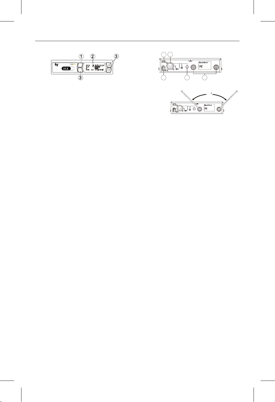
RE-2 Re ceiver Con trols, Con nec tors, and In di ca tors
Power ON/OFF
1.
Graph i cal Dis play
2.
a.
b.
c.
d.
e.
f.
g.
Re ceiver Setup and Op er a tion
Place the re ceiver and an ten nas where there is a
1.
clear line of sight to the area where the trans mit --
ter will be used. Ro tate the an ten nas to sep a rate
them by 90 de grees.
2. Con nect the power sup ply cord to the re ceiver.
Plug the power sup ply into an AC out let. Turn
the re ceiver on and con firm that it is ON by
check ing the main dis play screen.
Cau tion: Please make sure the AC power sup ply
is the cor rect volt age for your lo cal re quire ments
be fore it is plugged into the wall.
3. Man ual Chan nel Change. Press the SET but --
ton and the Group num ber will start to flash.
The Up and DOWN but tons al low you to scroll
through the fac tory set group. When the group
you de sire is dis played, press SET to se lect that
group and the Chan nel Num ber will start flash --
ing. Scroll to the de sired chan nel and press SET
to se lect. The num bers will stop flash ing and the
new group and chan nel are in stalled.
4. Fre quency As sign ment (Out side of pre set
Groups and Chan nels), press SET and UP at
the same time and the group and chan nel will go
blank and the Fre quency will start flash ing. Use
UP/DOWN to scroll in 25 KHz steps to the de --
sired fre quency. Press SET and the fre quency
will be se lected and stop flash ing. Press Set and
UP at the same time to re turn to group and chan --
nel op er a tion. Hint: hold ing in the Up or Down
key will in crease the speed of the scroll. Just re --
lease and press again for fine con trol
5. Ad vanced ClearScan: This fea ture au to mates
the pro cess of find ing a clear group of
inter-mod u la tion free chan nels and the clear est
chan nels within those groups.
Fig ure 1 - RE-2 Front Panel
Chan nel Dis play
Fre quency
Bat tery Strength
In di ca tor
Di ver sity In di ca tor
RF Strength of
Sig nal In di ca tor
Au dio Level In di ca tor
Gui tar Mode In di ca tor
Dis play Con trol But tons (Set/Up/Down)
3.
Power Con nec tor
4.
XLR BalancedMic/Line Level
5.
Au dio Out put Line Level Ad just able
Un bal anced Line Level Au dio Out put
6.
Con nec tor with Level Ad just ment
TNC An tenna In put Con nec tors
7.
Power Cord Re tainer
8.
-2-
Fig ure 2 - RE-2 Back Panel
Proper An tenna Orientation
a.
ClearScan for Groups: From the main dis --
play screen, push SET once and the Group
Num ber will flash. While Group is flash ing,
press and hold SET un til ClearScan ap pears,
re lease the set key. When the scan is com --
pleted, the dis play will show the group with
the most clear chan nels and the Chan nel num --
ber will in di cate how many clear chan nels are
in that group. Use the UP/DOWN keys and to
view other groups and press SET to se lect a
group. The Group will be set and the Chan nel
will start to flash. Se lect a chan nel man u ally
or use ClearScan for Chan nels.
b.
ClearScan for Chan nels: To scan for the
clear est chan nel in a group, press and hold set
while the Chan nel is flash ing un til ClearScan
ap pears, re lease the SET but ton. When the
scan is com plete, the dis play will show the
clear est avail able chan nel. Use UP/DOWN to
scroll through the other avail able chan nels
rank from clear est to least clear (but still avail --
able for use, ClearScan will not dis play any
chan nel that can't be used). Press SET to se --
lect the chan nel.
c.
Auto ClearScan: This func tion will find the
clear est group and chan nel with the press of
just one but ton. With noth ing flash ing, press
and hold the SET but ton un til ClearScan ap --
pears on the right side of the screen. When the
scan is com plete, the re ceiver will be set to the
clear est chan nel in the clear est group.
d.
ClearScan Band: While in the Fre quency
Mode, this func tion will scan the en tire band
look ing for the clear est fre quency, re gard less
of groups and chan nels. In Fre quency Mode,
press Set once and the fre quency will flash,
press and hold set until ClearScan ap pears on
the right side of the dis play. The scan will
con tinue un til you press Set again so you can
scan a lo ca tion over night, 24 hrs, a week, or a
few sec onds. When you press Set again, the
scan will stop and the clear est fre quency will
be dis played. You can scroll through the 8
clear est fre quen cies us ing the Up and Down
but tons. Press Set to ac cept the fre quency dis --
played.
Page 5
NOTE: Groups 9 and above are set up to work
with the other US fre quency band (A and B). If
you are us ing a mix of Band A and Band B, scroll
down to these groups and use the clear est group.
6. Change Lock-Out: By press ing and hold ing the
UP and DOWN ar row keys to gether for 3 sec --
onds, the SET key is dis abled.To re ac ti vate the
SET key, sim ply press and hold the UP and
DOWN keys again for 3 sec onds. This fea ture
can be use ful when the re ceiver is in a lo ca tion
where un au tho rized per son nel have ac cess to
the re ceiver.
For set up, make sure the mixer or amplifier in --
7.
put used for the RE-2 is muted or turned down
to a min i mum level.
Plug an au dio ca ble (not sup plied) into the 3 pin
8.
XLR or 1/4 inch out put of the RE-2.
a. NOTE: The XLR con nec tor is the pre --
ferred con nec tion since the out put is bal --
anced and will be more im mune to noise
for lon ger runs of ca ble al though ei ther
can be used with good re sults. If the 1/4
inch con nec tor is used, ad just the out put
level on the back panel to 12 o'clock (mid --
way in the range) to start and ad just later if
nec es sary.
Now re fer ahead to trans mit ter setup and re turn
to step 9 when that is com pleted.
With the trans mit ter on, speak into the mi cro --
9.
phone or play the guitar. Turn up the level on
the mixer or am pli fier un til you are able to hear
the de sired sig nal. If no au dio is pres ent, re peat
setup and re fer to the trou ble shoot ing sec tion.
NOTE: If the 1/4 inch out put is used, it may be
nec es sary to ad just the re ceiver out put un til the
vol ume level from the wire less sys tem ap prox i --
mates the level of an equiv a lent wired mi cro --
phone/in stru ment.
10. Squelch Ad just ment - The squelch set ting can
be used to max i mize range or im mu nity to
noise. Press and hold Up for 3 sec onds. The cur --
rent squelch set ting will be dis played. Ad just
the squelch us ing the UP/DOWN keys. Max i --
mum squelch (9) max i mizes noise im mu nity but
lim its the range. Min i mum squelch (1) will max i --
mize the range but al low more noise to break
through the squelch. Press SET to save the new
squelch set ting.
Re ceiver Push-But ton Ref er ence Sheet
Dis play Sta tus But ton Func tion Ac ti vated Edit Ac cept
Noth ing Flash ing Press and hold SET Auto ClearScan n/a n/a
Noth ing Flash ing SET Edit Group -Group will flash SET
Group Flash ing Press and hold SET ClearScan Group - list clear groups in or der SET
Group Flash ing SET Edit Chan nel - Chan nel will flash SET
Chan nel Flash ing Press and hold SET ClearScan Chan nel - list clear chan nels in or der SET
Noth ing Flash ing Press and hold Up Edit Squelch Set ting SET
Noth ing Flash ing Press and hold Up & Down Edit Lock - Se cure will ap pear n/a n/a
Edit Lock On Press and hold Up & Down Re turn to Ac cess Mode n/a n/a
Power Off Press and hold SET Tog gle be tween Gui tar and Voice mode n/a n/a
Noth ing Flash ing Press SET and Up Tog gle to Fre quency Mode - Freq will flash SET
Fre quency Flash ing Press and hold SET ClearScan Band - Clear Scan will flash n/a SET
ClearScan Band Run ning Press SET End ClearScan Band af ter next full scan n/a n/a
ClearScan Band Re sults n/a Clear est fre quen cies listed SET
Fre quency Mode Press SET and Up Re turn to Group and Chan nel Mode n/a n/a
Noth ing Flash ing Press and hold Down Dis play Soft ware Re vi sion n/a n/a
-3-
Page 6

Handheld Trans mit ter HTU-2
755050
11
22
33
77
99
SET
4
5 6
8
3
1
2
Fig ure 3
Handheld Trans mit ter
HTU-2 Con trols,
Con nec tors, and In di ca tors
Fig ure 4
Trans mitt er
1. Main Dis play - LCD
(Chan nel, Fre quency or Bat tery Level In di ca tion)
2. Bat tery Low LED - Lights when bat tery is low
3. Power On/Off Switch
4. Set Switch
Handheld Trans mit ter Setup
and Op er a tion
1. In sert Bat tery. Re move the bat tery com part --
ment cover by un screw ing it com pletely. In sert a
9V bat tery, ter mi nal end first into the bat tery
com part ment.
NOTE: The HTU-2 unique de sign al lows the
bat tery to be in serted and used re gard less of the
pos i tive and neg a tive ter mi nal po si tion.
2. With bat tery com part ment still open, turn the
unit so you can see the dis play and the con trol
panel. Turn the unit on by slid ing the power
switch for ward to the on po si tion. The bat tery
low LED will light for a sec ond and the dis play
will show the Group and Chan nel num bers.
3. Change the group and chan nel num bers to
match those dis played on the re ceiver by press --
ing SET. The Group num ber will flash and can
be changed with the UP/DOWN keys. Once the
de sired group num ber is show ing, press SET to
se lect and the Chan nel num ber will flash. Se lect
the Chan nel and press SET again. The flash ing
will stop and the chan nel is now set.
4. Other Screens: Press SET and DOWN at the
same time to dis play the bat tery level. Press
SET and DOWN again to dis play fre quency.
Press them one more time to re turn to Group
and Chan nel.
5. Chan nel/Fre quency Up Switch
6. Chan nel/Fre quency Down Switch
7. Mi cro phone Gain
8. 9V Bat tery Holder
9. Bat tery Cover - Screw type.
5. Fre quency Edit Mode - Press SET from the
fre quency dis play screen to en ter fre quency edit
mode. Press the Up and Down to ad just fre --
quency in 25 kHz in cre ments. Hold ing the Up or
Down but tons down will auto step the fre quency;
slowly at first, then quickly. You can also en ter
fre quency edit mode by press ing SET and UP at
the same time from ei ther the Group and Chan --
nel or Bat tery sta tus dis play screens. Press ing
SET and UP at the same time from the Fre --
quency dis play screen will en ter Group and
Chan nel edit mode.
6. Power Lock Out - Press SET, UP, and DOWN
at the same time and hold 3 sec onds to lock the
power switch on. To turn the unit off, place the
power switch in the OFF po si tion and push SET,
UP, or DOWN. To re move the lock, press SET,
UP, and DOWN again at the same time and hold
3 sec onds. A one-time only ON-LOCK mode
can also be en tered by quickly cy cling the
power switch three times.
7. Set Key Lock-Out, by press ing and hold ing the
UP and DOWN ar row keys to gether for 3 sec --
onds, the SET key is dis abled. To re ac ti vate the
SET key sim ply press and hold the UP and
DOWN keys again for 3 sec onds.
-4-
Page 7

8. Ver ify re cep tion. With the trans mit ter and re --
SETSET
6
9
5
4
2
3
755050755050
GPGP CHCH
1
8
5
755050755050
GPGP CHCH
RR
ceiver on and match ing Group and Chan nel, the
main re ceiver dis play should be in di cat ing a RF
sig nal on the bar graph. Speak into the mi cro --
phone and the Au dio Me ter bar graph should in --
di cate au dio sig nal pres ence. If the level me ters
do not show re cep tion, make sure the chan nels
are match ing and re fer to the trou ble shoot ing
sec tion.
9. Ad just ment of the trans mit ter au dio gain - If
nec es sary The trans mit ter au dio gain is fac tory
set at the mid dle of the range, which should be
suit able for most ap pli ca tions. For loud or soft
speak ers/sing ers, a gain ad just ment may be nec --
es sary. Have the speaker or singer use the mi --
cro phone in a nor mal per for mance level voice.
The Au dio Me ter in the main re ceiver dis play
screen should show peaks around the -3dB
level. If the me ter peaks all the way to the right
or well be low the -3dB level, ad just the trans --
mit ter au dio gain.
Bodypack Trans mit ter - BPU-2
To ad just the trans mit ter gain, gently in sert the
pro vided screw driver (or other 3/32 - 2.5 mm
screw driver) into the ad just ment hole above the
dis play screen. Turn lightly un til the screw --
driver tip goes into the ad just ment level con trol
Gently turn coun ter clock wise un til the con trol
stops (the mi cro phone out put is at min i mum but
not off). Slowly turn the gain con trol up (clock --
wise) while speak ing/sing ing into the mi cro --
phone and au di om e ter shows peaks around -3
dB.
NOTE: Op er at ing with the trans mit ter au dio
gain set as high as pos si ble (with out dis tor tion
or peaks all the way to the right end of the me --
ter) will re sult in the best per for mance and high --
est sig nal to noise ra tio.
Test Per for mance. Go back to Sec tion 3. Re --
10.
ceiver Setup and Op er a tion - Step 9 to com plete
sys tem set up and test.
Fig ure 6
Con trol View
Fig ure 5
Bodypack Trans mit ter
BPU-2 Controls, Con nec tors,
and In di ca tors
An tenna - flex i ble 1/4 wave an tenna
1.
Power On/Off Switch
2.
Bat tery Low LED In di ca tor
3.
TA4 Au dio Con nec tor
4.
LCD Dis play (Chan nel, Fre quency or
5.
Bat tery Level In di ca tion)
Fig ure 7
Top View
Dis play Con trol But tons (Set/Up/Down)
6.
Belt Clip (Re mov able, not shown)
7.
9V Bat tery Compartment
8.
Au dio Gain Adjustment
9.
-5-
Page 8

Bodypack Trans mit ter Setup
and Op er a tion
1. In sert Bat tery. Pinch the bat tery door tabs in --
ward and pull the door open. In sert a 9V bat tery
as in di cated by the +/- in the holder.
With bat tery com part ment still open, turn the
2.
unit on with Power switch on the top panel. The
bat tery low LED will light for a sec ond and the
dis play will show the Group and Chan nel num --
bers.
3. Change the group and chan nel num bers to
match those dis played on the re ceiver by press --
ing SET. The Group num ber will flash and can
be changed with the UP/DOWN keys. Once the
de sired Group num ber is show ing, press SET to
se lect and the Chan nel num ber will flash. Se lect
the Chan nel and press SET again, the flash ing
will stop and the chan nel is now set.
4. Set Key Lock-Out. By press ing and hold ing the
UP and DOWN ar row keys to gether for 3 sec --
onds, the SET key is dis abled. To re ac ti vate the
SET key, sim ply press and hold the UP and
DOWN keys again for 3 sec onds.
5. Ver ify re cep tion. With the trans mit ter and re --
ceiver on and match ing Group and Chan nel, the
main re ceiver dis play should be in di cat ing a RF
sig nal on the bar graph. If the level me ter does
not show re cep tion, make sure the chan nels are
match ing and re fer to the trou ble shoot ing sec --
tion.
6. At tach the Mi cro phone or Gui tar.
Mi cro phone: Plug the mi cro phone ca ble into
the top panel of the BPU-2. Speak into the mi --
cro phone and the Au dio Me ter bar graph should
in di cate au dio sig nal pres ence.
Gui tar: Turn off the bodypack, press and hold
SET while you turn the bodypack on. A gui tar
sym bol will ap pear in the dis play to in di cate in --
stru ment mode. Re peat the pro cess hold ing SET
on the re ceiver as it is pow ered up. Plug in the
MAC-G3 gui tar ca ble. Strum the gui tar and the
Au dio Me ter bar graph on the re ceiver should
in di cate au dio sig nal pres ence.
7. Ad just ment of the Trans mit ter Au dio Gain (if nec es sary). The trans mit ter au dio gain is fac --
tory set at the mid dle of the range, which should
be suit able for most ap pli ca tions. For loud or
soft speak ers/sing ers, a gain ad just ment may be
nec es sary.
Have the speaker or singer use the mi cro phone
in a nor mal per for mance level voice. The Au dio
Me ter in the main re ceiver dis play screen should
show peaks around the -3 dB level. If the me ter
peaks all the way to the right or well be low the
-3 dB level, ad just the trans mit ter au dio gain.
To ad just the trans mit ter gain, gently in sert the
pro vided screw driver (or other screw driver) into
the ad just ment po ten ti om e ter. Gently turn coun --
ter clock wise un til the con trol stops (the mi cro --
phone out put is at min i mum but not off). Slowly
turn the gain con trol up (clock wise) while
speak ing/sing ing into the mi cro phone or strum --
ming the gui tar and the au di om e ter shows peaks
around -3 dB.
NOTE: Op er at ing with the trans mit ter au dio
gain set as high as pos si ble (with out dis tor tion
or peaks all the way to the right end of the me --
ter) will re sult in the best per for mance and high --
est sig nal to noise ra tio.
Other Screens: Press SET and DOWN at the
same time to dis play the bat tery level. Press
SET and DOWN again to dis play fre quency.
Press them one more time to re turn to Group
and Chan nel.
8. Fre quency Edit Mode - Press SET from the
fre quency dis play screen to en ter fre quency edit
mode. Press the Up and Down to ad just fre --
quency in 25 kHz in cre ments. Hold ing the Up or
Down but tons down will auto step the fre quency;
slowly at first, then quickly. You can also en ter
fre quency edit mode by press ing SET and UP at
the same time from ei ther the Group and Chan --
nel or Bat tery sta tus dis play screens. Press ing
SET and UP at the same time from the Fre --
quency dis play screen will en ter Group and
Chan nel edit mode.
9. Power Lock Out - Press and hold SET, UP, and
DOWN at the same time and hold for 3 sec onds
to lock the power switch on. To turn the unit off,
place the power switch in the OFF po si tion and
push SET, UP, or DOWN. To re move the lock,
press SET, UP, and DOWN again at the same
time and hold for 3 sec onds. A one-time only
ON-Lock mode can also be en tered by quickly
cy cling the power switch three times.
10. Test Per for mance - Go back to Sec tion 3 - Re --
ceiver Setup & Op er a tion, Step 9 to com plete sys --
tem set up and test.
AP PROVAL IN FOR MA TION
The Elec tro-Voice/Telex Trans mit ters are Type Ac cepted un der United States Fed eral Com mu ni ca tions
Com mis sion CFR 47, Part 74 and In dus try Can ada RSS123.
The Elec tro-Voice/Telex Re ceiver is ap proved un der United States Fed eral Com mu ni ca tions Com mis --
sion CFR 47, Part 15 and In dus try Can ada RSS210.
Li cens ing of Elec tro-Voice/Telex equip ment is the us ers re spon si bil ity and Licensability de pends upon
the us ers clas si fi ca tion, us ers ap pli ca tion and fre quency se lected. Elec tro-Voice/Telex strongly urges
the user to con tact the ap pro pri ate tele com mu ni ca tions au thor ity for any de sired clar i fi ca tion.
CAU TION: Any changes or mod i fi ca tions made to the above equip ment could void the us ers au thor ity to
op er ate the equip ment.
-6-
Page 9

Sec tion 4 - Re ceiver Dis play Screens and Func tions
-20 -10 -5 0 +3-20 -10 -5 0 +3
1 3 10 30 1001 3 10 30 100
AFAF
RR
FF
CLEARSCANCLEARSCAN
TMTM
1
3
2
7 5
8
6
9
4
-20 -10 -5 0 + 3-20 -10 -5 0 + 3
1 3 10 30 1001 3 10 30 100
AFAF
RR
FF
Main Op er at ing Screen
Fig ure 8
Main Op er at ing Screen
1. Group Num ber···············10 (fac tory set)
2. Chan nel Num ber ···················01 to 10
3. Fre quency ···········Dis played in Mega Hertz
4. Bat tery Sta tus ················100 to 0 Pct in
5. Au dio VU Me ter ··········-30 VU to + 3 VU
6. RF Sig nal Strength ···········1 µV to 100 µV
7. An tenna Di ver sity Sta tus ···left or right an tenna
8. ClearScan ········In di cates Scan is in prog ress
9. Gui tar Sym bol ······In di cates In stru ment Mode
Squelch Ad just ment Screen
Dis play:
25 Pct steps/Flash if low
1. Press and hold SET for 3 sec onds starts AutoClearScan™
2. Press SET once, Group starts flash ing, ad just with
UP and DOWN.
2.a With Group flash ing, press and hold SET for 3
seconds to start Group Scan
3. Press SET twice, Chan nel starts flash ing, ad just
with UP and DOWN.
3.a With Chan nel flash ing, press and hold SET for
3 sec onds to start Chan nel Scan
4. Press SET and UP at the same time to en ter Fre --
quency Mode
5. Press and hold UP for 3 sec onds to ad just Squelch
6. Press and hold SET dur ing power up to en ter In --
stru ment Mode
7. [UP] + [DOWN] for 3 sec onds Sets/Re sets Edit
Lock out
Con trols:
Dis play:
Squelch Adjustment Screen
1. Squelch Level ·················1-10
Trans mit ter Dis play and Con trols
Dis play:
Controls:
Fig ure 10
Trans mit ter Dis play and Con trols
Fig ure 9
Con trols:
1. [UP] + [DOWN] ad just the squelch level
2. SET saves the squelch level shown and re turns
you to the main screen
1. Group and Chan nel
2. Bat tery Level in Per cent age
3. Fre quency
1. Press SET once, GP will flash, use UP and
DOWN to ad just
2. Press SET again to ac cept GP, CH will flash, ad just
with UP/DOWN
3. Press SET again to ac cept CH and chan nel
will be in stalled
4. Press SET and DOWN at the same time to change
dis play mode
5. Press SET and UP to en ter Fre quency Set Mode
6. Press SET and DOWN to re turn to the
Group/Chan nel Mode
7. Press and hold UP and DOWN for 3 sec onds
to lock out SET
8. Press and hold UP and DOWN again to ac ti vate SET
9. Press and hold UP, DOWN, and SET
to lock power (see Sec tion 4)
10. Press and hold UP, DOWN, and SET to un lock power
-7-
Page 10

Trans mit ter On/Off Lock-Out
There are two On/Off lock out modes avail able, One
Time and Everytime.
One Time: Cy cle the power switch 3 times in un der
3 sec onds and On-Loc will be dis played for a sec --
ond and then re turn to nor mal op er a tion. The power
switch alone will no lon ger turn the unit off. To turn
the unit off, put the power switch in the off po si tion
(On-Loc will be dis played) open the bat tery door
and press [Set], [Up], or [Down] and the unit will
power down. The next time the unit is pow ered on,
the power switch will op er ate nor mally.
Everytime Use: With the unit on and op er at ing in
the nor mal mode, press and hold [Set], [Up], and
[Down] for 3 sec onds. On-Loc will be dis played
and the power switch alone will no lon ger turn the
unit off. To turn the unit off, put the power switch in
the off po si tion, (On-Loc will be dis played), open
the bat tery door and press [Set], [Up], or [Down]
and the unit will power down. The next time the
unit is pow ered on, the On-loc func tion will still be
on. To en able the power switch, press and hold
[Set], [Up], and [Down] for 3 sec onds (On-Off will
be dis played).
Guide lines and Rec om men da tions
for Best Per for mance
Com pat i bil ity
The trans mit ter and re ceiver must be of the same
fre quency band and set to the same group and chan --
nel in or der to work to gether. The RE-2 is avail able
in different fre quency bands. The band in for ma tion
is avail able in the Group/Chan nel edit screen on the
re ceiver, the bot tom la bel on the handheld trans mit --
ter, and on the back panel la bel on the bodypack.
Us ing Mul ti ple Wire less Sys tems
If two or more RE-2 sys tems and/or other
UHF/VHF wire less sys tems are be ing used in the
same lo ca tion, proper fre quency co or di na tion is
nec es sary to avoid in ter fer ence. All chan nels in the
RE-2 fac tory set groups are de signed to work
together, so if chan nels from just one group are used
no fur ther coordination is re quired. Con tact your
dealer or Telex for as sis tance if you are plan ning
more sys tems or us ing the RE-2 with other wire less
equip ment.
IM POR TANT NOTE: Al ways use the
small est pre set group that meets your
needs. For in stance, if you want to set up
6 units, use one of the groups of 8 fre --
quen cies. The smaller the pre set group,
the more com pat i ble the fre quen cies are.
Mul ti ple Sys tems
and Ad vanced ClearScan
Be cause all of the chan nels in the fac tory set groups
are com pat i ble, Ad vanced ClearScan can be used to
set up mul ti ple sys tems quickly and with con fi --
dence. When set ting up more than one sys tem, set
up the first sys tem us ing the Auto-ClearScan
func tion.
TM
Once the work ing Group has been es tab lished,
leave the first trans mit ter on, set the next re ceiver
Group to the work ing Group and run ClearScan for
Chan nels. This will pro vide the next clear est chan --
nel in that group. Set the trans mit ter to match, leave
it on and re peat un til all the sys tems are set up. If
you run out of clear chan nels in one group but need
to set up more sys tems, con tact your dealer or Telex
for as sis tance in choos ing ad di tional fre quen cies.
Po ten tial Sources of In ter fer ence
There are many po ten tial sources of in ter fer ence for
your wire less sys tem. Any elec tronic prod uct
that con tains dig i tal cir cuitry in clud ing dig i --
tal sig nal pro ces sors (re verb/multi-effects
units), elec tronic key boards, dig i tal light ing con trol --
lers, CD and DVD play ers, and com put ers, all emit
RF en ergy that can ad versely af fect the per for mance
of your wire less sys tem. It is al ways best to place
the re ceiver as far away as pos si ble from these de --
vices to min i mize po ten tial prob lems.
An a log and Dig i tal Tele vi sion stations can also in --
ter fere with your wire less sys tem. The RE-2 is de --
signed to op er ate over 28 MHz of RF band width,
which cov ers six TV chan nels. The fac tory pre sets
on the RE-2 are op ti mized for conditions where
one, two, or pos si bly three of the six stations are
cov ered in your area. If four or more of the six sta --
tions are used in your area, it will se verely limit the
num ber of sys tems that will op er ate to gether and
you should be us ing a dif fer ent band.
Bat tery Rec om men da tions
Fresh 9-volt al ka line bat ter ies form a qual ity man u --
fac turer will yield the best per for mance from your
RE-2 trans mit ters. Re charge able 8.4-volt Ni-Cad
bat ter ies can be used but will re sult in much shorter
op er a tion time.
When the trans mit ters are turned on, the red bat tery
LED will flash once if the bat tery is good. If the
light does not light or stays lit con tin u ously, the bat --
tery is weak or dead. If the light co mes on dur ing
use, the bat tery is weak en ing and should be re --
placed as soon as pos si ble. If sound qual ity de --
grades during use, it may be the re sult of a
weak en ing bat tery.
Cau tion: The bat tery level in di ca tors, on the
trans mit ters and re ceiver dis plays, are based on
the use of al ka line bat ter ies. Use of other bat tery
types will re sult in false read ings on these in di ca --
tors al though the bat tery low LED on the trans --
mit ters will op er ate nor mally.
Re ceiver and An tenna Place ment
Do not place the re ceiver near a large metal ob ject
or sur face. Lo cate the re ceiver as close as pos si ble
to the area where the trans mit ter will be used. Ide --
ally, po si tion the re ceiver/an ten nas within sight of
the trans mit ter. When us ing mul ti ple sys tems, do
not al low an ten nas to cross or touch each other. For
best re sults with mul ti ple re ceiv ers, use an APD4
an tenna split ter. (See Sec tion 7).
-8-
Page 11

Sec tion 5 - Trou ble Shoot ing Guide
Prob lem
No au dio and no dis play on
the re ceiver
No au dio and no RF sig nal
in di ca tor on the re ceiver dis --
play
No Au dio with good RF sig --
nal in di ca tor but no (or low)
Au dio in di ca tor on the re --
ceiver dis play
No (or low) Au dio with good
RF sig nal and Au dio in di ca --
tors on re ceiver dis play
Dis torted au dio sig nal
In ter fer ence
Pos si ble Causes
Re ceiver is off
Trans mit ter is off
Trans mit ter is on a dif fer ent
chan nel
No (or dead) bat tery in trans --
mit ter
Faulty bat tery con tacts
Mi cro phone not con nected
Low gain set ting on the
trans mit ter
Re ceiver au dio out put ca ble
is dam aged or dis con nected
Gain not suf fi cient on
mixer/preamp/amp in put or it
is muted
Re ceiver out put too low
(1/4" out put)
Trans mit ter au dio gain
too high
Re ceiver out put too high
(1/4" out put)
Bat tery level low in
trans mit ter
An other RE-2 sys tem in the
in stal la tion is on the same
chan nel or the sig nals are
mix ing
An other wire less prod uct in
the area is on the same fre --
quency or the sig nals are
mix ing
So lu tions
Make sure that the power
sup ply is prop erly con nected
and the on/off but ton is in
the on po si tion
Turn on trans mit ter power
switch
Match the trans mit ter group
and chan nel to the one dis --
played on the re ceiver.
In sert fresh bat tery in trans --
mit ter
Clean and or bend con tact
Check the TA4F con nec tor
on the bodypack or the de --
tach able mi cro phone el e ment
con nec tion on the handheld
In crease the trans mit ter gain
Con nect, re pair or re place
ca ble
In crease gain on mixer or
un-mute the in put
In crease the au dio out put
set ting
De crease the trans mit ter gain
set ting
De crease the re ceiver out put
set ting
In sert fresh bat tery in
trans mit ter
Make sure all the chan nels in
use are from the same group.
Use ClearScan to se lect the
clear est group. If more chan --
nels are needed call Telex at
800-392-3497 for co or di na --
tion help
Use ClearScan to change the
op er at ing fre quency. If prob --
lems per sist, call Telex at
800-392-3497 for co or di na --
tion help
-9-
Page 12

Trou ble Shoot ing Guide (con tin ued)
Prob lem
In ter fer ence (con tin ued)
Short range or drop-outs
Can't change set tings on
re ceiver or trans mit ter
Pos si ble Causes
Re ceiver is too close to dig i --
tal sig nal pro ces sor or sim i lar
de vice
Strong elec tro mag netic field
from stage light ing or other
source near the trans mit ter or
re ceiver, which may be pro --
duc ing RF noise at or near
the op er at ing fre quency
RF re flec tive metal ob sta cles
be tween the trans mit ter and
receiver
Poorly ori ented beltpack
antenna
Faulty re ceiv ing an tenna
system
Lock-out fea ture is en abled
So lu tions
Move the re ceiver to a
dif fer ent lo ca tion
Use ClearScan to change the
op er at ing fre quency. Re pair
or re move the source of in --
ter fer ence. Move the re ceiver
to a dif fer ent lo ca tion
Move the ob sta cles, or re po --
si tion the re ceiver/an ten nas
Check the an tenna con nec --
tion and re-ori ent the
bodypack so the an tenna is
ver ti cal ( up and down) and
fac ing the re ceiver, if pos si --
ble
Check all an tenna con nec --
tions and re po si tion to be in
line-of-sight with the trans --
mit ter
Dis able lock out
(see pages 3 and 8)
Bodypack or Handheld
trans mit ter will not turn off,
dis play says On-Loc
On/Off lock-out is engaged
-10-
Put the on/off switch in the
off po si tion and press one of
the pro gram ming but tons
(see page 8)
Page 13

Sec tion 6 - Tech ni cal Spec i fi ca tions
RE-2 Re ceiver
Spec i fi ca tions
Re ceiver Type ....................................................Syn the sized PLL
Fre quency Range (RF) .....................A Band 648 - 676 MHz (TV Chan nels 43 - 48)
Num ber of Chan nels ...................................... >1122 pos si ble frequencies
Mod u la tion ...........................................................+/- 40 kHz
Di ver sity ........................................Dig i tal Posi -PhaseTM True Di ver sity
RF Sen si tiv ity ............................................<1.0 µV for 12 dB SINAD
Im age Re jec tion ..........................................................>60 dB
Squelch .................................................Tone Code plus Am pli tude
Ul ti mate Quieting ........................................................>100 dB
FCC Cer tif i ca tion ...........................................Ap proved un der Part 15
Power Re quire ments .........................................12-15V AC/DC, 300mA
Op er at ing Tem per a ture....................................-7° to 49° C (20° to 120° F)
Re ceiver Di men sions ................................1.72 in. H x 7.50 in. W x 5.9 in. D
Fre quency Re sponse ............................................50 - 15 kHz +/- 2dB
Bal anced Out put (typ i cal) .................................. (max @ 40 kHz de vi a tion)
Un bal anced Out put ......................ad just able 10 mV to 1V RMS, 100K OHM Load
Dis tor tion .............................<1.0%, 0.5% typ i cal (ref 1kHz, 40kHz de vi a tion)
Sig nal-to-Noise Ra tio ...........................................>100 dB A Weighted
Dy namic Range .........................................................>100 dB
Trans mit ters BPU-2 and HTU-2
Over all
B Band 696 - 724 MHz (TV Chan nels 54 - 56)
Pro gram ma ble in 25 kHz steps
43.69 mm H x 190.50 mm W x 150 mm D
Au dio Pa ram e ters
330mV RMS 100K OHM Load, Mic Po si tion
10mV to 2V RMS 100K OHM Load, Line Po si tion
Ra di ated Out put ...................................................30 mW Typ i cal
Mi cro phone Head ElectroVoice 767a.............N/D 767a supercardioid N/DYM dy namic
Mi cro phone Head ElectroVoice 267a .........................N/D 267a cardioid dy namic
Mi cro phone Head ElectroVoice RE410 ........................RE410 cardioid con denser
Stan dard Lavalier Mi cro phone .......EV RE90Tx MicroMiniä Omni-Dierctional Con denser
TA4F Con nec tor Wir ing ................................Pin 1: Ground; Pin 2 Mic In put;
Au dio Gain Ad just ment Range .........................................40 dB BPU-2
Power Re quire ments ..........................................9 Volt Al ka line Bat tery
Bat tery Life (Typ i cal) .............................>8 hours with 9-Volt Al ka line Typ i cal
Bodypack An tenna ........................................Flex i ble ex ter nal 1/4 wave
Handheld An tenna ................................................In ter nal 1/2 wave
Di men sions (Handheld) ........................................24.0 cm (9.4 in.) Long
Di men sions (bodypack) ..............................3.8 in. H x 2.38 in. W x 0.92 in. D
-11-
Pin 3: +5V bias; Pin 4: +5V bias
96.5 mm H x 60.5 mm W x 23.4 mm D
through a 3kW re sis tor
26 dB HTU-2
Page 14

Sec tion 7 - Ac ces so ries and Parts
MODEL No. Or der No.
Omnidirectional La pel Mi cro phone OLM10 OLM10
Uni di rec tional La pel Mi cro phone UML21 ULM21
Pre mium Omnidirectional La pel Mi cro phone RE90TX 17153318
Pre mium La pel/In stru ment
Uni di rec tional Mi cro phone RE92TX 301456000
Pre senter's Headworn Mi cro phone HM2 HM2
Singer's Headworn Mi cro phone HM7 HM7
Hard Shell, Foam lined Road Case RC-RE2 7185800
Foam Wind screen for Handheld 379-1 3792031
Handheld Trans mit ter Color Kit HHCK 7185700
Bodypack Pouch WP-1000 879553
Gui tar Cord MAC-G3 879706
Sin gle Re ceiver Rack Mount Kit RMS 71081001
Sin gle Rack Mount Kit with front RMS-TNC 71081004
mount an tenna ca bles
Dou ble Rack Mount Kit RM-D 71081002
Front Mount An tenna Ca bles (4) FMC-K 878978
1/4 Wave Rx An tenna ANU-14 879010
1/2 Wave Rx An tenna FA-500 860031
(All Bands) (680-870 MHz)
1/2 Wave An tenna Mount ing AB-2 71138000
Bracket with 10' of Coax
An tenna/Pwr Dis tri bu tion APD4 APD4
Ter mi na tion Plug for APD4 TP-2 650095
Di rec tional Rx An tenna LPA500 LPA500
(450-900MHz) (A/B)
Low Loss Co ax ial An tenna Ca ble CXU-25 71151025
(25, 50, 75, 100 ft. with TNC Con nec tors) CXU-50 71151050
600-746 MHz
730-890 MHz
600-780 MHz
780-900 MHz
ANU-14H
APD4-1
CXU-75 71151075
CXU-100 71151100
-12-
879010-1
APD4-1
Page 15

Sec tion 8 - Fac tory Ser vice/War ranty (Lim ited)
FAC TORY SER VICE (North Amer ica)
If fac tory ser vice is re quired, ship the unit pre paid in its orig i nal car ton to:
EV Au dio Ser vice
c/o TELEX COM MU NI CA TIONS,
8601 East Cornhusker High way,
Lin coln, Ne braska 68507-9702 U.S.A.
Phone: (402) 467-5321 or 800-553-5992
Fax: 402-467-3279
En close a note de scrib ing the prob lem along with any other per ti nent in for ma tion and how to con --
tact you.
Fac tory Ser vice (Ex clud ing North Amer ica)
If fac tory ser vice is re quired, ship the unit pre paid in its orig i nal car ton to:
En close a note de scrib ing the prob lem along with any other per ti nent in for ma tion and how to con tact
you.
War ranty (Lim ited)
Elec tro-Voice prod ucts are guar an teed against mal func tion due to de fects in ma te ri als or work man --
ship for a spe cific pe riod, as noted in the in di vid ual prod uct-line state ments(s) be low, or in the in di --
vid ual prod uct data sheet or owner's man ual, be gin ning with the date of orig i nal pur chase. If such
mal func tion oc curs dur ing the spec i fied pe riod, the prod uct will be re paired or re placed (at our op --
tion) with out charge. The prod uct will be re turned to the cus tomer pre paid via UPS Ground.
Ex clu sions and Lim i ta tions: The Lim ited War ranty does not ap ply to: (a) ex te rior fin ish or ap pear --
ance; (b) cer tain spe cific de scribed in the in di vid ual prod uct-line state ment(s) be low, or in the in di --
vid ual prod uct data sheet or owner's man ual; (c) mal func tion re sult ing from use or op er a tion of the
prod uct other than as spec i fied in the prod uct data sheet or owner's man ual; (d) mal func tion re sult --
ing from mis use or abuse of the prod uct; or (e) mal func tion oc cur ring at any time af ter re pairs have
been made to the prod uct by any one other than Elec tro-Voice or any of its au tho rized ser vice rep re --
sen ta tives.
Ob tain ing War ranty Ser vice: To ob tain war ranty ser vice, the cus tomer must de liver the prod uct,
pre paid, to Elec tro-Voice or any of its au tho rized ser vice rep re sen ta tives to gether with proof of pur --
chase of the prod uct in the form of a bill of sale or re ceipted in voice. A list of au tho rized ser vice rep --
re sen ta tives is avail able from Elec tro-Voice.
In ci den tal and Con se quen tial Dam ages Ex cluded: Prod uct re pair or replacement and re turn to the
cus tomer are the only rem e dies pro vided to the cus tomer. Elec tro-Voice shall not be li a ble for any
in ci den tal or con se quen tial dam ages in clud ing, with out lim i ta tion, in jury to per sons or prop erty or
loss of use.
In ci den tal and Con se quen tial Dam ages Ex cluded: Prod uct re pair or re place ment and re turn to the
cus tomer are the only rem e dies pro vided to the cus tomer. Elec tro-Voice shall not be li a ble for any
in ci den tal or con se quen tial dam ages in clud ing, with out lim i ta tion, in jury to per sons or prop erty or
loss of use.
Other Rights (United States Only): This war ranty gives you spe cific le gal rights and you may also
have other rights, which vary from state to state.
Elec tro-Voice RE-2 Wire less sys tems are guar an teed against malfunction due to de fects in ma te ri als
or work man ship for a pe riod of two (2) years from the date of orig i nal purchase. The Lim ited War --
ranty does not ex tend to ca bles or ca ble con nec tors. Ad di tional de tails are in cluded in the Uni form
Lim ited War ranty State ment. Tech ni cal As sis tance; 800-392-2497 (U.S. and Can ada only)
Telex EVI Au dio GmbH
Hirschberger Ring 45
D-94315 Straubing
Tele phone: +49 (0) 9421 7070
Fax: +49 (0) 9421 706 350
-13-
Page 16

TELEX COM MU NI CA TIONS, INC. 12000 Port land Ave. South, Burnsville, MN 55337
PN 803673 Aug 2003 Made in U.S.A.
 Loading...