


R200 SERIES WIRELESS
OWNER’S MANUAL

R200 OWNERS MANUAL
TABLE OF CONTENTS
DESCRIPTION.......................................................................................................................................... |
3 |
R200 SERIES COMPONETS ................................................................................................................... |
3 |
QUICK SETUP AND USE ..................................................................................................................... |
4-5 |
COMPATIBILITY ...................................................................................................................................... |
6 |
POTENTIAL SOURCES OF INTERFERENCE ........................................................................................ |
6 |
BATTERY RECOMMENDATIONS ........................................................................................................... |
6 |
SPECIFICATIONS .................................................................................................................................... |
7 |
FCC REGULATIONS................................................................................................................................ |
8 |
WARRANTY ............................................................................................................................................. |
8 |
IN CASE OF DIFFICULTY ....................................................................................................................... |
9 |
page 2

R200 OWNERS MANUAL |
Description |
R200 SERIES OWNER’S MANUAL
System Features
•True-diversity system with Secure-Phasetm ensures maximum range and freedom from interference
•Well-designed companding and audio circuitry insure high signal-to-noise ratio and excellent sound quality
•Choice of handheld, bodypack, lavalier, headset and guitar systems
•Permanently attached antennas make setup quick and easy. Receivers may be rackmounted with optional kit.
•Audio output via 3-pin XLR-type balanced mic level and ¼-inch unbalanced line level connectors
•Designed and manufactured in the United States of America
DESCRIPTION
The Electro-Voice R200 is a series of UHF wireless systems that combine EV’s legendary quality, reliability and high value. The R200 Series transmitters and receivers operate in the UHF frequency range between 710.100 and 721.350 MHz
(channels 54-55 in the TV band) on single frequencies. The well-designed audio circuitry ensures excellent signal-to-noise ratio with accurate sound quality.
SECURE-PHASEtm DIVERSITY
The R200 Series receivers utilize patented Se- cure-Phasetm diversity circuitry that provides the strongest, cleanest signal possible. Unlike other diversity circuits that switch antennas, Secure-
Phasetm utilizes the signal from both antennas at all times to increase signal strength, minimize dropouts and lower the potential for interference.
If the signal from the transmitter changes phase or polarity (a common cause of dropouts), the circuit adjusts the phase angle between the two antennas receiving circuits to prevent cancellation.
R200 SERIES COMPONENTS
R200 Secure-Phasetm Diversity UHF Receivers
•Secure-Phasetm diversity for maximum range and reliability
•Clean, undistorted sound reproduction using proprietary compander circuitry
•Audio output via rear-mounted XLR-type 3-pin mic level or front-mounted, adjustable line level
¼-inch connector
•May be rack mounted with optional kit
•External AC power adapter minimizes noise and makes voltage changes easy if necessary.
Power can also be supplied from a 12-volt battery or filtered power supply.
•Permanently attached, specially-tuned antennas are easy to position
•RCU: UHF receiver specially designed to reproduce all the nuances of the voice
•GRU: UHF guitar receiver specially designed to handle the transients of a guitar
The R200 Series receivers are easy to set up and operate. The only controls are the adjustable output level and squelch controls. The antennas are permanently attached telescoping types that are easy to position and are tuned to the range of operation. An optional rack-mount kit allows two systems to be mounted in a single rack space.
HTU Handheld Transmitter
•Electro-Voice BK-1 (HTUC) cardioid condenser microphone transducer or Electro-Voice N/ D157 (HTUD) cardioid N/DYM dynamic transducer.
•Separate LEDs for power on and battery status for easy monitoring of operational modes.
•Separate power and audio mute switches for operational flexibility.
•Wide-range gain control allows approximately 40 dB of adjustment.
•Special “soft-touch” finish and ergonomically designed handle makes holding comfortable and secure.
•Up to 10 hours of operation on a 9-volt alkaline battery.
Bodypack Transmitters
•Two models are available:
•BPU: UHF bodypack with TA4F connector allows the user the freedom of microphone selection. Standard microphones include the
Electro-Voice ULM20 cardioid condenser lavalier microphone and the HM2 headset microphone. The TA4F connector allows connection of any dynamic or condenser microphone that can be biased with 5 volts dc phantom.
•BGU: UHF guitar bodypack with hardwired cable and ¼-inch connector with specially designed audio circuitry to handle guitar transients
•Separate on/off and large mute switches for operational flexibility
•LED battery condition indicator gives quick indication of battery strength
page 3
R200 OWNERS MANUAL
•Up to 10 hours of operation on a 9-volt alkaline battery
QUICK SETUP AND USE
To get your system into operation quickly, use the following instructions. Review the rest of the manual for additional setup and operational details.
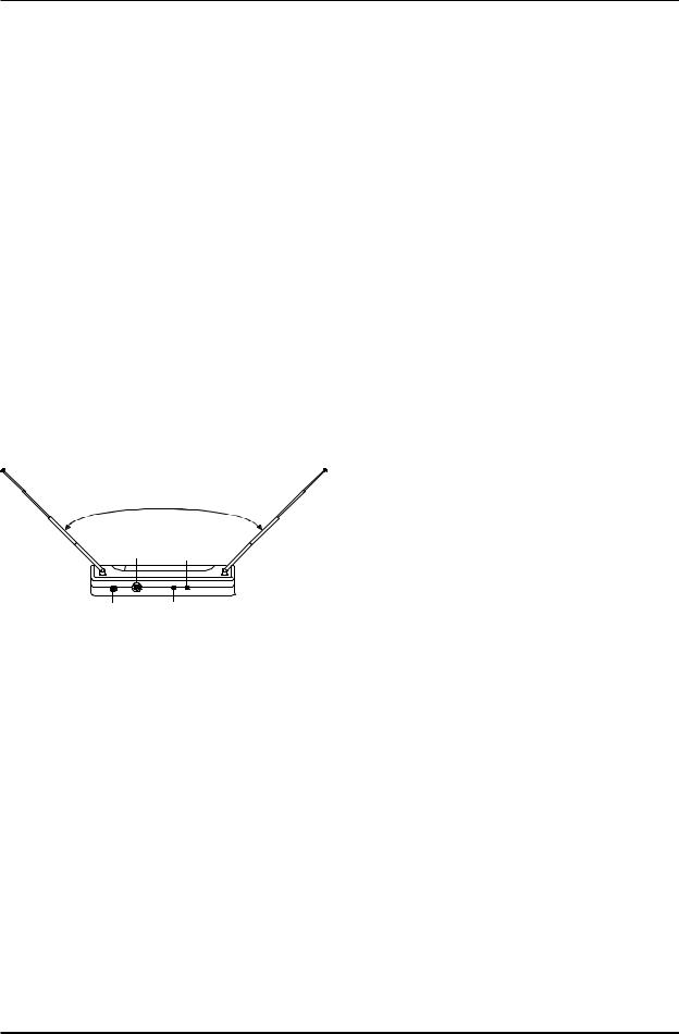
1.Place the receiver where there is a clear line of sight to the area where the transmitter will be used (Figure 1). Extend the receiver’s antennas and separate them 90 degrees (see
Figure 2).
2.Make sure the sound system’s volume is low or off on the input you intend to use for the wireless.
3.Plug in the receiver’s power adapter into an
AC outlet and the other end into the receiver.
CAUTION: Please make sure that the AC adapter is the correct voltage for your local requirements.
4.Plug the audio cable (not supplied) into either output connector. The 3-pin XLR-type con-
nector is the preferred choice since the output is balanced. Either connector may be used with good results.
5.Turn the output level control (see Figure 2) on the front panel to the 12:00 o’clock position
(midway in the control’s range) if the ¼-inch connector is used (the 3-pin XLR-type connector has fixed level).
6.Setup and adjust the transmitter level as described on the following pages.
7.Turn up the level on the mixer or preamp to the desired setting.
8.Speak into the microphone or strum the instrument and, if necessary, adjust the receiver’s output until the volume level from the wireless system approximates the level of an equivalent wired microphone or instrument.
9.“Walk” the expected area of use to check for dropouts or interference. If problems occur, see the troubleshooting section.
Figure 1
S E T A N T E N N A S
A T 9 0 D E G R E E S
A U D I O O U T P U T |
P O W E R |
|
J A C K |
||
L IG H T |
||
|
V O L U M E |
C A R R IE R |
L E V E L |
( T R A N S M I T T E R O N ) |
C O N T R O L |
L IG H T |
|
HTU HANDHELD TRANSMITTER SETUP
1.Insert battery. Slide open the battery compartment cover by placing your thumb on the indents of the battery door (at the back end of the transmitter) and gently pull down (see Figure 3).
2.Turn on the transmitter by sliding the power switch (closest to the battery compartment) forward to its on position, toward the mic element. The red battery condition light should flash once and then go out. If the red LED stays on or illuminates during a performance, it should be replaced immediately. The green LED will stay lit when the transmitter is on.
3.Check reception. Observe that the audio carrier light on the front panel of the receiver is illuminated, an indication that the receiver is picking up the signal. Then, “walk” the intended area of use and make sure that there are no barriers to reception or sources of interference.
4.Unmute the audio by sliding the audio switch
(immediately below the mic element) towards the windscreen.
5.Adjust the gain if necessary. First, speak or sing into the microphone and listen closely for distortion or hiss. If the gain is too low or high, adjustments are necessary. Gently insert the provided screwdriver (or other 3/32-in. screwdriver) into the hole near the head of the transmitter (see Figure 4). Turn lightly until the screwdriver tip drops into the slot in the level control. Gently turn counterclockwise until the control stops (the mic output is attenuated but not “off”). Slowly turn the miclevel control while listening to the audio. If the audio becomes distorted, turn the mic level control counter-clockwise about 1/8 turn.
6.Adjust the squelch control if necessary.
The squelch control on the back of the receiver may be adjusted to increase range or reduce interference. Turn the control counter-
page 4
 Loading...