


Q44/Q66 PROFESSIONAL AMPLIFIER
OWNER’S MANUAL

IMPORTANT SAFETY INSTRUCTIONS
The lightning flash with arrowhead symbol, within an equilateral  triangle is intended to alert the user to the presence of uninsulated
  “dangerous voltage” within the product’s enclosure that may be
  of sufficient magnitude to constitute a risk of electric shock to persons.
 The exclamation point within an equilateral triangle is intended
  to alert the user to the presence of important operating and
  maintance (servicing) instructions in the literature accompanying the appliance.
1.Read these instructions.
2.Keep these instructions.
3.Heed all warnings.
4. |
Follow all instructions. |
5.Do not use this apparatus near water.
6. |
Clean only with a dry cloth. |
7.Do not block any of the ventilation openings.
|
Install in accordance with the manufacturer’s instructions. |
8. |
Install only in rack with back cover. |
9. |
Only use attachments/accessories specified by the manufacturer. |
10.Refer all servicing to qualified service personnel. Servicing is required when the apparatus has been
damaged in any way, such as power-supply cord or plug is damaged, liquid has been spilled or objects have fallen into the apparatus, the apparatus has been exposed to rain or moisture, does not operate normally, or has
|
been dropped. |
11. |
To completely disconnect mains power from this apparatus, the power supply cord must be unplugged |
For US and CANADA only:
Do not defeat the safety purpose of the grounding-type plug. A grounding type plug has two blades and a third grounding prong. The wide blade or the third prong are provided for your safety. When the provided plug does not fit into your outlet, consult an electrican for replacement of the obsolete outlet.
IMPORTANT SERVICE INSTRUCTIONS
CAUTION: These servicing instructions are for use by qualified personnel only. To reduce the risk of electric shock, do not perform any servicing other than that contained in the Operating
Instructions unless you are qualified to do so. Refer all servicing to qualified service personnel.
1. Security regulations as stated in the EN 60065 (VDE 0860) and the CSA E60065-00 have to be obeyed when
servicing the appliance.
2. Use of a mains separator transformer is mandatory during maintenance while the appliance is opened, needs to be
operated and is connected to the mains
3. Switch off the power before retrofitting any extensions, changing the mains voltage or th e output voltage.
4. The minimum distance between parts carrying mains voltage and any accessible metal piece (metal enclosure), respectively between the mains poles has to be 3 mm and needs to be minded at all times.
The minimum distance between parts carrying mains voltage and any switches or breakers that are not connected
to the mains (secondary parts) has to be 6 mm and needs to be minded at all times.
5. Replacing special components that are marked in the circuit diagram using the security symbol (Note) is only permissible when using
original parts.
6. Altering the circuitry without prior consent or advice is not legitimate.
7. Any work security regulations that are applicable at the location where the appliance is being serviced have to be strictly obeyed. This applies also to any regulations about the work place itself.
8. All instructions concerning the handling of MOS - circuits have to be observed.
Note:  SAFETY COMPONENT (HAS TO BE REPLACED WITH ORIGINAL PART ONLY)
2

DESCRIPTION
C O N T E N T S
Description . . . . . . . . . . . . . . . . . . . . . . . . . . . . . . . . . . . . . . . . . . . . . . . . . . . . . . . . . . . 3
Front Panel . . . . . . . . . . . . . . . . . . . . . . . . . . . . . . . . . . . . . . . . . . . . . . . . . . . . . . . . . . . 4
Rear Panel. . . . . . . . . . . . . . . . . . . . . . . . . . . . . . . . . . . . . . . . . . . . . . . . . . . . . . . . . . . . 5
Specifications . . . . . . . . . . . . . . . . . . . . . . . . . . . . . . . . . . . . . . . . . . . . . . . . . . . . . . . . . 7
Block diagram . . . . . . . . . . . . . . . . . . . . . . . . . . . . . . . . . . . . . . . . . . . . . . . . . . . . . . . . |
8 |
Dimensions . . . . . . . . . . . . . . . . . . . . . . . . . . . . . . . . . . . . . . . . . . . . . . . . . . . . . . . . . . . 9
Warranty . . . . . . . . . . . . . . . . . . . . . . . . . . . . . . . . . . . . . . . . . . . . . . . . . . . . . . . . . . . . . 12
D E S C RIP T I ON
First of all, we would like to express our thanks and at the same time congratulate you on the decision to buy one of our Q-SERIES power amplifiers.
ElectroVoice Q-SERIES amplifiers are made to meet the highest requirements of any on-the-road application. Thus they provide on-board protection against thermal and capacitive overload, short-circuit and the occurrence of HF or DC at the output. Additionally, special circuitry prevents the output-stage transistors from being damaged by Back-EMF. During soft start, delayed switching of the power outputs is accomplished via relays and a limiter controls the initial current inrush, preventing the mains fuse from being blown during the power-on operation.
The mechanical construction as well is carried out following the highest precision standards of the industry. The robust steel chassis provides extreme rigidity and it is meant to live through any hard wearing condition of a touring application. Thermal stability is guaranteed by two 3-Mode silently running fans that offer the possibility to also use the amplifiers in a studio environment.
The extensive comparator circuitry constantly monitors the input and output signals and activates the internal limiters whenever a non-linear operational state is encountered. This provides reliable protection of the connected loudspeaker systems against overload and clipping. The sound quality of the Q-SERIES power amplifiers is superb. Using comprehensive dimensioned power supply units with low-interference toroidal transformers gains a headroom that exceeds the nominal power handling capacity by far. No V/I-Foldback-Limiter circuits are employed within the power amplifiers, making it possible to operate the amps on complex loads up to ±90° phase angles without a problem.
The input facilities are carried out as balanced XLRF-type sockets while the Direct-Outs – on which the carried-through signals are present – come as XLRM-type connectors. Using the Input Routing-switches lets you determ ine if the Q-SERIES amplifiers are operated in DUAL (stereo) or PARALLEL (monaural) mode; “mono-bridged” operation is also possible.
The dB-scaled level controls are to be found on the rear panel. These potentiometers guarantee precise and reliable operation. The easy readable LED display on the front panel offers quick optical information on the power amplifiers’ momentary operational mode. For each channel individually the display shows whether they are operational, a signal is present at the outputs, when the limiters are activated, and whether one of the protection circuits has been engaged or not. The power outputs CANNEL A, CHANNEL B and BRIDGED OUT are carried out as Speakon connectors. A ground-lift switch that separates the enclosure from the appliance’s ground potential and therefore helps to eliminate ground noise loops and the mono bridged mode switch are also located on the rear panel. In normal operation all Q-SERIES power amplifiers can be used to drive loads down to 2 ohms; in bridged mode the minimal load is 4 ohms. All amps are equipped with extremely silent running fans providing front-to-rear air circulation, guaranteeing trouble-free operation even in smaller power amplifier rack systems.
Studying this owner’s manual carefully will provide you with further and more detailed in formation about the Q-SERIES power amplifiers. Thus we recommend to keep on reading, assuring you that the Electro Voice Q-SERIES power amplifiers will provide you with a lot of fun and satisfaction in your work.
3
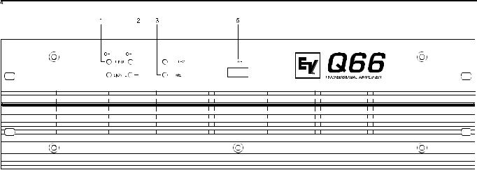
FRONT PANEL
1. LIMIT
This indicator lights when the amplifier enters clipping and the internal limiter is activated. Short-term indication is problem-free. Anyway, if this indicator lights continuously, reducing the overall volume is recommended to avoid that the connected loudspeaker systems are getting damaged from overload.
2. SIGNAL INDICATOR
This indicator lights when an output signal is present. In case of short-circuited speaker cabling or one of the amplifier’s protection functions is engaged the indicator is off, showing that there is no signal outputted.
3 . PROTECT
If this indicator lights during operation, one of the amp’s internal protection functions against thermal overload, short-circuit, occurrence of HF or DC at the output … has been engaged. The cause that let the amplifier enter the protection mode – e. g. a short-circuited speaker cable – has to be eliminated. In case of thermal overload you have to wait until the power amplifier returns into normal operation mode.
4 . POWER ON INDICATOR
This LED lights when the appliance’s power switch has been engaged. If the indicator does not light after you have engaged the power switch, either the amplifier is not connected to the mains or the internal mains fuse is blown and has to be replaced.
5 . POWER SWITCH
Using the POWER switch you turn the amplifiers power on. To eliminate unwanted noise and knacks in the connected speaker systems, loudspeaker output switching is performed delayed via relays. An initial current inrush limiter prevents the mains fuse from being blown during power-on.
4
 Loading...