

Page 1
Op er ating In struc tions
RE-1
User Guide
Page 2

Table of Contents
Quick Set-Up ..................................................................................1-1
Quick Set-up: Re ceiver .......................................................................1-1
Quick Set-up: Transmitter.....................................................................1-1
QuickSet-up:Sys tem Op er a tion................................................................1-1
Sys tem De scrip tion .............................................................................2-1
De tailed Com po nent De scrip tions .................................................................3-1
CSR-1000 Re ceiver Con trols, Con nec tors and In di ca tors ..........................................3-1
CSR-1000 Re ceiver Setup and Op eration .......................................................3-2
CSH-1000 Handheld Transmitter .............................................................3-4
CSH-1000 Handheld Transmitter Setup and Op eration ...........................................3-5
CSB-1000 Bodypack Trans mit ter..............................................................3-6
CSB-1000 Bodypack Trans mit ter Setup and Op er a tion ...........................................3-7
Transmitter Dis play Screens and Func tions .....................................................3-8
Receiver Dis play Screens and Func tions............................................................4-1
Main Op er ating Screen ......................................................................4-1
Dis play................................................................................4-1
Con trols ...............................................................................4-1
Group / Chan nel Edit Screen .................................................................4-2
Dis play................................................................................4-2
Con trols ...............................................................................4-2
Frequency Edit (User Groups Only) ...........................................................4-3
Dis play................................................................................4-3
Con trols ...............................................................................4-3
Func tions Screen ...........................................................................4-4
Con trols ...............................................................................4-4
ClearScan
ClearScan
ClearScan
Edit Microphone Label / Name ...............................................................4-6
Sound Check Screen ........................................................................4-6
Set Squelch Threshold .......................................................................4-6
Copy Group ...............................................................................4-7
Screen Timer ..............................................................................4-7
Clear Group ...............................................................................4-7
Lock out ...................................................................................4-7
Mas ter Re set ...............................................................................4-7
Trans mit ter On/Off Lock out..................................................................4-7
Guide lines and Rec om men da tions for Best Per for mance ..............................................5-1
Trou ble Shoot ing Guide .........................................................................6-1
Technical Spec i fi ca tions .........................................................................7-1
CSR-1000 Re ceiver .........................................................................7-1
CSB-1000 Beltpack Trans mit ter...............................................................7-2
CSH-1000 Handheld Transmitter .............................................................7-2
Cer tif i ca tions ..................................................................................7-3
Ac ces sories and Parts ...........................................................................8-1
Cus tomer Ser vice In for ma tion....................................................................9-1
Limited Warranty .............................................................................10-1
TM
All ............................................................................4-4
TM
Current Groups .................................................................4-5
TM
Band ..........................................................................4-5
Dis play................................................................................4-6
Con trols ...............................................................................4-6
Dis play................................................................................4-6
Con trols ...............................................................................4-6
Dis play................................................................................4-6
Con trols ...............................................................................4-6
Com pat i bil ity ...........................................................................5-1
Using Mul ti ple Wire less Sys tems ............................................................5-1
Mul ti ple Sys tems and Ad vanced ClearScan
TM
..................................................5-1
Bat tery Rec om men da tions .................................................................5-1
Receiver and An tenna Place ment ............................................................5-1
-i-
Page 3

Quick Set-up: Receiver
Do not connect the receiver to any other equip ment yet!
1.
Connect the two an tennas to the receiver.
2.
Plug the power supply into the back of the re ceiver and
3.
into an out let
Press the POWER switch. Dis play will light up, show
4.
information and software revision numbers for about 3
seconds and then display the main op erating screen.
Press the MENU button twice to dis play the ClearScan
5.
op tion screen.
With the CLEARSCAN ALL line indicated press SET.
6.
ClearScan
7.
ClearScan
8.
Press SET again.
The display will return to the main op erating screen with
9.
the clear est chan nel in the clear est group as signed.
Turn the re ceiver off and con nect the mixer or other au dio
10.
system to the re ceiver XLR Mic Level Connector or the ¼
inch Line Level Jack.
Set the audio mixer or other system in put level to mini-
11.
mum.
TM
re turns the clear est group. Press SET again.
TM
re turns the clearest chan nel in that group.
TM
Section
Quick Set-Up
Use the up and down arrows to change the Group number
5.
to match the channel number displayed on the re ceiver.
Press SET and the Chan nel Number will flash.
Use the up and down arrow but tons to change the Channel
6.
to match the receiver. Press Set and flashing stops. The
channel is now set.
If you are us ing a bodypack transmitter, plug the mi cro-
7.
phone into the transmitter con nector. If us ing a guitar,
place the In strument/Mic switch un der the battery door in
the Instrument po sition and plug the cord into the transmitter and gui tar.
Transmitter “Quick Set-up” is com plete.
Quick set-up: Sys tem Op er a tion
With the transmitter and re ceiver on, monitor the
1.
CSR-1000 Re ceiver main dis play screen. Note that the RF
(1-100) Bar graph should in dicate near the 100 mark. The
AF Bar should show very little, if any, in dication un til you
talk or sing into the microphone. Ad just the transmitter
gain control if nec essary to cause the AF Bar Graph to
peak near -6 to -3 but not over +3 for best per formance.
1
Press the Power switch button in again.
12.
Receiver “Quick Set-up” is com plete.
Quick set-up: Transmitter
With the Power Switch on the transmitter OFF, in stall a
1.
fresh al kaline battery into the transmitter.
Place the transmitter Power Switch to the ON position.
2.
The Red Low Bat tery Light near the dis play will flash on
3.
and then off. The display will also come on briefly, dis play ing bat tery level.
The screen will stop at the GP (Group) and CH (Channel)
4.
screen. Press the SET but ton once and the Group number
will flash.
1-1
Set the mixer or other system gain.
2.
Talk or sing into the microphone or play the instrument at
3.
a nor mal volume. You should hear au dio coming out of the
sys tem.
If us ing the un balanced 1/4" output, you may have to ad-
4.
just the gain (via the control next to the connector on the
back panel) to match the level found when singing or playing with a wired con nection.
"Quick Set-up" is now complete.
Please enjoy your RE-1 system.
Page 4

1-2/Blank
Page 5

Section
2
Sys tem De scrip tion
The CSR-1000 Wire less Mi cro phone sys tem com bines frequency agility and ease of use like no other. The CSR-1000
transmitters and re ceivers operate over a 24 MHz bandwidth
in the UHF por tion of the spectrum.
Sys tem Fea tures In clude:
Ad vanced ClearScanTM technology for selecting clear channels and compatible groups
•
960 Ra dio Channels, user pro grammable or fac tory in stalled
•
LCD Displays for ease of viewing
•
Patented DSP Phase Diversity Sys tem
•
USB Port for downloading soft ware enhancements in the re ceiver
•
Adjustable Un balanced Line Level 1/4 inch output jack
•
Fixed bal anced Mi cro phone Level XLR out put jack
•
Front Panel Power ON/OFF Switch
•
Qua dru ple Tuned Ce ramic Res o na tor front end for su pe rior in ter fer ence re jec tion
•
SAW Filter 1st I.F for out of band re jection
•
The high qual ity au dio circuitry and ad vanced Ra dio Frequency (RF) signal processing offer broadcast quality signal-to-noise and au dio clarity.
Triple ce ramic fil ters in 2nd I.F for ad jacent chan nel re jection
•
Dou ble Tuned Quad ra ture cir cuit for low au dio dis tortion
•
Per ma nent Flash Mem ory for fre quency/sys tem stor age.
•
Front Panel Soft ware Control of Squelch settings
•
Double Squelch (Amplitude and Tone) system pre vents false squelch
•
Lock out fea ture to pre vent ac ci den tal chan nel changes
•
Sound Check mode to speed walk testing and provide tangible results
•
"Smart" bat tery fea ture in the transmitter means there is no wrong orientation
•
Interchangeable heads on the handheld transmitter
•
Over-molded Warmgrip™ han dle on the handheld transmitter
•
Cast magnesium case on the bodypack trans mit ter
•
2-1
Page 6

2-2/Blank
Page 7
CSR-1000 Receiver
Antenna
Made in U.S.A.
Program
Patent No. 6256484
Balanced
Mic Level
Output
Unbalanced
Line Level
Output
Antenna
MIN
MAX
FMR
12 - 15V
AC/DC
CSR-1000
Testedto Comply
with FCC Standards
F
C
C
A 0001000
7 5
6
7
4
R
8
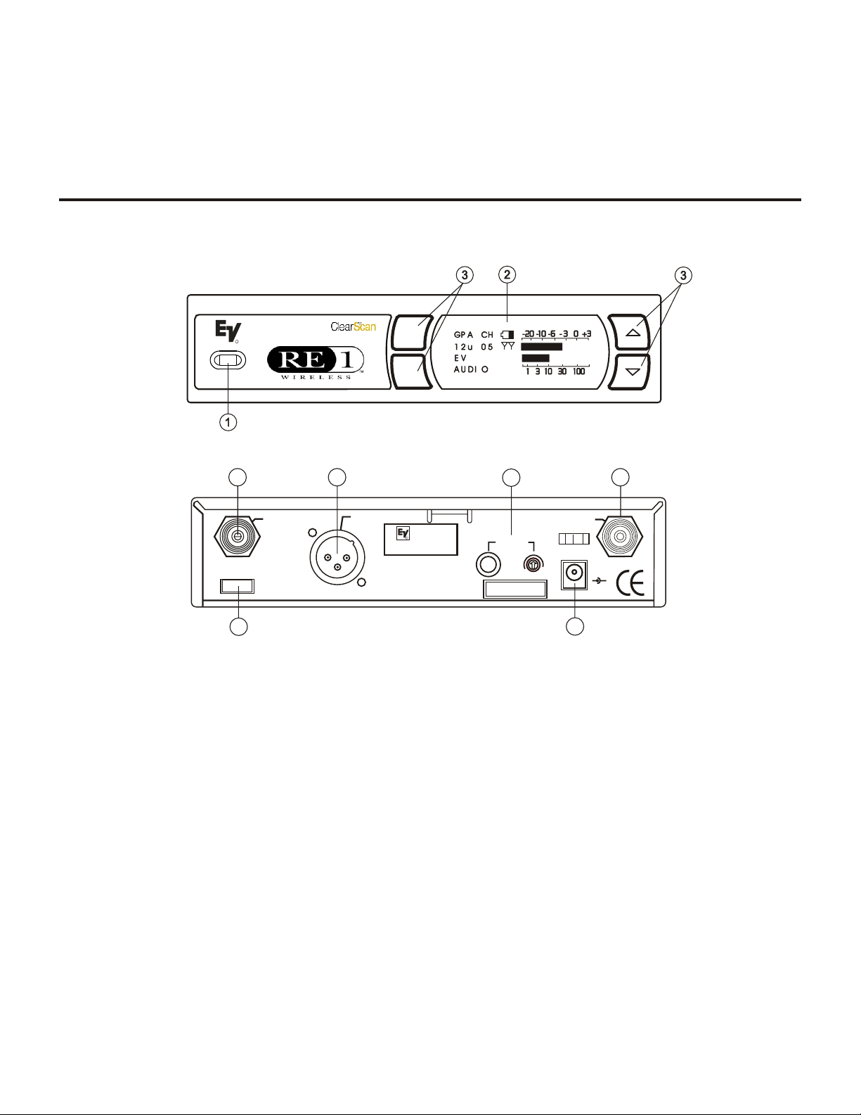
CSR-1000 Re ceiver Con trols, Con nec tors
and In di ca tors
Section
3
Detailed Compo nent De scrip tions
power
R
CSR-1000 UHF Receiver
menu
set
Fig ure 1
CSR-1000 Front Panel
+-
Fig ure 2
CSR-1000 Back Panel
1. Power ON/OFF
2. Graph i cal Dis play
Chan nel Dis play
a.
Bat tery Strength In di ca tor
b.
Di ver sity In di ca tor
c.
RF Strength of Signal Indicator
d.
Au dio Level In di ca tor
e.
3. Dis play Con trol But tons (Menu/Set/Up/Down)
4. Power Con nec tor
5. Balanced Mic Level Au dio Out put
6. Un bal anced Line Level Au dio Out put Con nec tor with
Level Ad just ment
7. TNC An tenna In put Con nec tors
8. USB Pro gram Con nec tor
3-1
Page 8

Re ceiver Setup and Op er a tion
Place the re ceiver and an tennas where there is a clear line
1.
of sight to the area where the transmitter will be used. Ro tate the an tennas to separate them by 90 de grees.
2. Connect the power sup ply cord to the receiver. Plug the
power sup ply into an AC outlet. Turn the re ceiver on and
confirm that it is ON by checking the main display screen.
The display will show the company logo, software and
channel map re vision levels and then dis play the main
screen with the last chan nel set.
Caution: Please make sure the AC power sup ply is the cor rect voltage for your lo cal requirements be fore it is
plugged into the wall.
3. Man ual Chan nel Change. From the main dis play screen
press the MENU but ton once. The Channel Change screen
is now displayed. Press SET: the group number should be
flashing. The Up and DOWN buttons allow you to scroll
through the 10 factory groups and 10 user de finable
groups. When the group you desire is displayed, press SET
to select that group and the Chan nel Number will start
flashing. Scroll to the de sired chan nel, press SET to select.
Pressing MENU anytime be fore pressing SET ne gates any
changes made since the last SET. Once the de sired group
and channel are displayed (but not flashing) press MENU
twice to re turn to the main display screen.
4. Frequency As signment (User De fined Groups Only).
With a User Group* se lected in step three, press MENU
once and the frequency as signment screen is displayed.
Press SET and the Fre quency Number will flash. Use
UP/DOWN to scroll in 25 kHz steps to the desired fre quency. With the desired fre quency dis played press SET.
The Channel Number will be gin to flash. use the
UP/DOWN keys to select an other Chan nel in this group
you want to as sign a fre quency, press SET to select and the
Frequency Number will flash. Re peat until all de sired
Channels are assigned a fre quency. Press MENU to stop ed iting. Press MENU twice to return to the main display
screen.
HINT: Hold ing in the arrow key will increase the speed of
the scroll. Just release and press again for fine con trol.
* User Defined Groups start at Group #11 and display a "u"
after the group number.
TM
This fea ture au tomates the pro-
5. Ad vanced ClearScan
cess of find ing a clear group of inter-modulation free
channels and the clearest chan nels within those groups. To
use ClearScan
TM
, from the main display screen push Menu
twice (or 3 times if a user de fined group is being used) to
go to the Op tions Screen. Use the UP/DOWN keys and
SET to select the ver sion of ClearScan
:
TM
, you wish to run.
TM
a. ClearScan
All. This pro gram scans all of the groups
(factory and user) and re turns a list of groups ranked by
the number of free channels. Once ClearScan
TM
All has
run, the screen will display the clearest group with the
open channels in that group. You can scroll through the
other ranked groups us ing UP/DOWN. When you have the
group you want, press SET to run ClearScan
TM
on that
group. The display will now show the group with the
Channels ranked by clearness. You can scroll through the
channels with UP/DOWN, once the de sired chan nel is
flashing, press SET to select and the display will go to the
main display.
NOTE: Groups 7, 8, 9, and 10 have 16 channels and are
marked with an N (7N). These groups re quire the transmitters
to be in the NORMAL transmit power set ting to work together. The N groups will always be displayed af ter groups
1-6 and any user defined groups no matter how many channels
are free. If you need to use more than 12 systems at one time,
scroll down to the N groups and use the clearest group with
Nor mal trans mit power.
b. ClearScan
TM
Group XX. This pro gram will scan the
group cur rently se lected, which is useful for multi-system
setup. With ClearScanTM All run for the first unit of a
multi-system in stallation, the clear est group has been selected. For each sys tem added, leave all pre viously se lected channel transmitters on, us ing Step 3 select the
TM
current group, se lect ClearScan
Group and press SET.
The display will show the group and ranked re maining
clear chan nels. Se lect the de sired channel with UP/DOWN
or simply press SET for the first chan nel. The channel will
be selected and re turn to the main display. Repeat un til all
systems are set up or all clear channels are full.
c. ClearScan
TM
Band. This pro gram se lects and ranks the
clearest 16 fre quencies in the 24 MHz band width re gardless of groups, chan nels or pre vi ous co or di na tion. This
feature is use ful for se lecting one clear chan nel in a very
dirty RF en vironment. From the Options screen, select
TM
ClearScan
Band and press SET, this scan will run un til
SET is pressed again so it can be used to eval uate a site
over an hour, day or even a week. The pro gram dis plays
Group 21S with the clearest open fre quencies in the band
assigned chan nels (up to 16). These fre quencies will remain assigned to this group un til ClearScan
TM
Band is run
again.
Caution: Un like the fac tory as signed groups, the chan nels
in 21S are not co ordinated. If more than one chan nel from
group 21S is used, the com bination must be walk tested
with all transmitters on before use.
3-2
Page 9

6. Change Lock-Out. By pressing and holding the UP and
DOWN ar row keys to gether for 3 seconds, the SET key is
disabled. The MENU button still al lows dif ferent screens
to be displayed but no settings can be changed and
TM
ClearScan
will not run. To reactivate the SET key sim ply press and hold the UP and DOWN keys again for 3
seconds. This feature can be use ful when the re ceiver is in
a lo ca tion where un au tho rized per son nel have ac cess to
the re ceiver.
For set up, make sure the mixer or other system in put used
7.
for the CSR-1000 is muted or turned down to a minimum
level.
Plug an au dio cable (not sup plied) into the 3 pin XLR or
8.
1/4 inch out put of the CSR-1000.
a. NOTE: The XLR con nector is the pre ferred con-
nection since the out put is balanced and will be
more immune to noise for longer runs of cable although either can be used with good results. If the
1/4 inch con nector is used, ad just the out put level
on the back panel to 12 o'clock (midway in the
range) to start and ad just later if necessary.
Walk Test the ex pected area of use to check for coverage.
10.
The SOUND CHECK screen is designed to aid this test.
From the main dis play screen, press MENU twice (3 times
in user groups) to dis play the op tions screen. Scroll down
to Sound Check and press set. This Sound Check Screen
will be dis played:
a. The peak hold au dio me ter allows you to set the
transmitter gain as high as pos sible for the ap plication which max imizes the signal to noise ratio.
Sing, yell or play the in strument at the loud est de sired vol ume and adjust the gain on the meter.
b. The squelch break coun ter will tell you if you
are pushing the range or may have some in terference prob lems to contend with. Ideally this count
would be zero for the de sired performance area.
If there are sev eral squelch breaks while walking
the area, adjust antenna place ment or squelch as
in step 11 and re test. Pressing [UP] will turn on
an au dible tone that will sound each time the
count is in cremented. This tone can be sent to the
monitors or PA so the tester can hear when a drop
occurs and mark the lo cation on the stage.
Pressing [DOWN] turns the tone off.
Now refer ahead to transmitter setup and return to step 9
when that is com pleted.
With the transmitter on, speak into the microphone or play
9.
the instrument. Turn up the level on the mixer or amplifier
until you are able to hear the de sired sig nal. If no au dio is
present, re peat setup and re fer to the troubleshooting section.
NOTE: If the 1/4 inch out put is used, it may be nec essary
to ad just the re ceiver output un til the vol ume level from
the wire less sys tem ap proximates the level of an equiv alent wired mi cro phone/in stru ment.
c. The high/low RF me ter will tell you if you have
adequate coverage in the performance area. If the
RF level drops significantly dur ing a walk of the
de sired area, re po si tion the an ten nas, ad just the
squelch or change the chan nel and re test.
CAUTION: MUTE OR TURN DOWN THE MIXER OR
AU DIO AM PLI FIERS ETC. BE FORE AD JUSTING THE
SQUELCH. OPEN (MIN IMUM) SQUELCH CAN RE SULT IN LOUD WHITE NOISE OVER THE AU DIO
SYS TEM.
11. Squelch Ad just ment - The squelch setting can be used to
maximize range or immunity to noise. Turn the transmitter
off and from the re ceiver Options screen se lect Squelch
Adjustment and press SET. The current squelch setting
will be dis played, the set ting bar will flash and "Tones
Off" will be displayed (the tone coded por tion of the
squelch must be off in or der to no tice any changes in the
amplitude squelch setting). Ad just the squelch using the
UP/DOWN keys and walk test the unit. Maximum squelch
(all the way right) max imizes noise im munity but lim its
the range. Minimum squelch (all the way left) will max imize the range but al low more noise to break through the
squelch.
3-3
Page 10
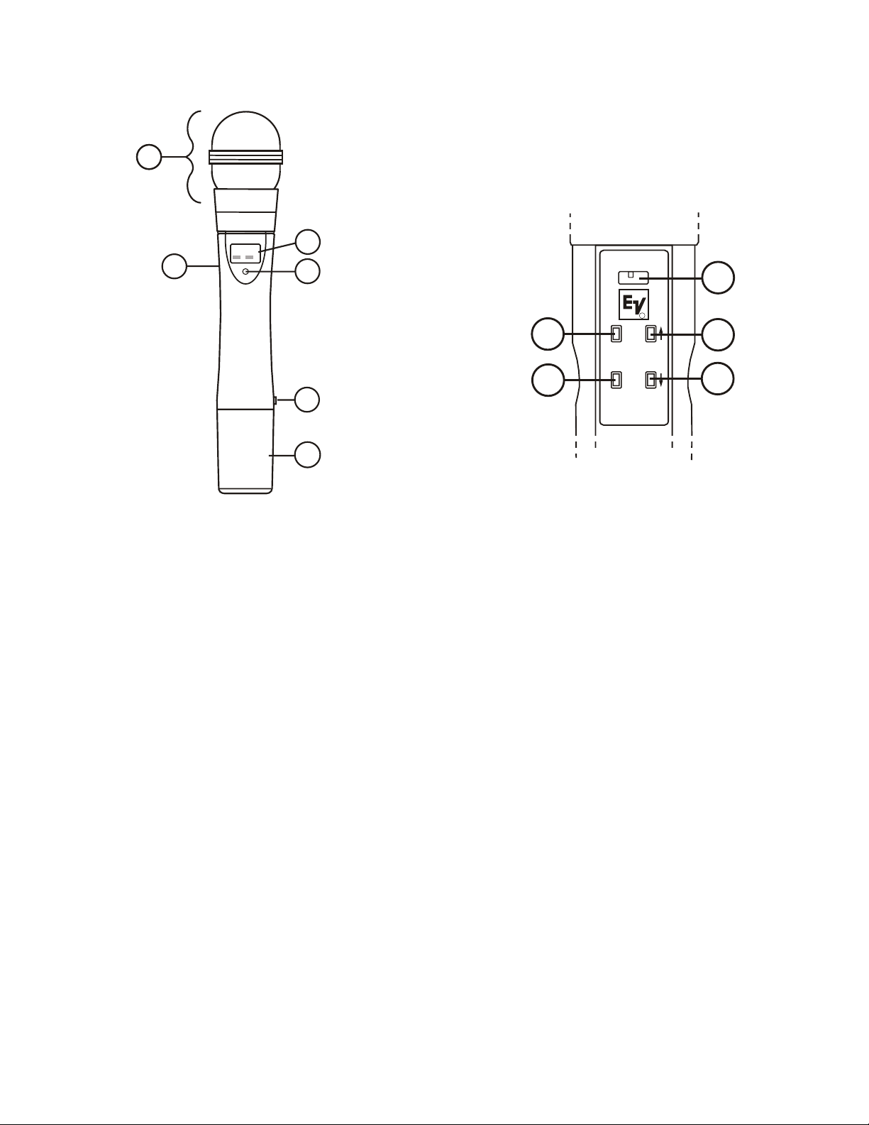
Handheld Trans mit ter CSH-1000
(ON OPPOSITE SIDE)
MADE IN U.S.A.
S
E
T
M
E
N
U
N
O
R
M
H
I
G
H
TRANSMIT
POWER
B
1
755050
9
Fig ure 3
Handheld Trans mit ter
2
3
4
10
5
6
Fig ure 4
Trans mit ter Con trols
11
R
7
8
CSH-1000 Con trols, Con nec tors and In di ca tors
Mi cro phone Head - In ter change able
1.
Main Display - LCD (Channel, Fre quency or Bat tery Level Indication)
2.
Low Battery LED - Lights when battery is low
3.
Power On/Off Switch
4.
Menu Switch
5.
Set Switch
6.
Chan nel/Fre quency Up Switch
7.
Chan nel/Fre quency Down Switch
8.
Mi cro phone Gain
9.
Battery Cover - Screw type
10.
Transmit RF Power Switch
11.
3-4
Page 11

Handheld Trans mit ter Setup
and Operation
Insert Bat tery. Re move the battery com partment cover by
1.
unscrewing it com pletely. Insert a 9V bat tery, terminal end
first into the battery compartment.
NOTE: The CSH-1000 unique design allows the battery to be
inserted and used re gardless of the pos itive and negative termi nal po si tion.
With bat tery compartment still open, turn the unit so you
2.
can see the display and the con trol panel. Turn the unit on
by sliding the power switch for ward to the on po sition.
The low battery LED will light for a second and the dis play will show the battery level, then the Group and Channel numbers.
3. Change the group and chan nel num bers to match those
displayed on the re ceiver by pressing SET. The Group
number will flash and can be changed with the UP/DOWN
keys. Once the de sired group number is show ing, press
SET to se lect and the Channel num ber will flash. Se lect
the Channel and press SET again, the flashing will stop
and the chan nel is now set.
4. Change Lock-Out. By pressing and holding the UP and
DOWN ar row keys to gether for 5 seconds, the SET key is
disabled. The MENU button still al lows dif ferent screens to
be dis played. To re activate the SET key, sim ply press and
hold the UP and DOWN keys again for 5 seconds.
NOTE: Operating with the transmitter audio gain set as high
as pos sible (without distortion or peaks all the way to the right
end of the meter) will result in the best performance and high est signal to noise ratio.
7. Trans mitting Power Ad just ment (if nec es sary).
CSH-1000 transmitter has two ra dio transmit power set tings. It is factory set in the NORM position, which will
maximize the number of simultaneous us ers and limit in terference with other wireless de vices. Switching to HIGH
power will maximize range for outdoor and single user ap pli ca tions.
8. In ter change able Mi cro phone Head. To re move the head,
grasp the handheld transmitter body in one hand and the
ballscreen as sembly in the other. Turn the ballscreen coun ter clock wise and un screw until the head is de tached. See
spec i fi ca tions and ac ces so ries for more in for ma tion on
avail able heads.
9. Test Per for mance. Go back to Sec tion 3. Re ceiver Setup
and Op eration - Step 9 to complete system set up and test.
The
5. Ver ify re cep tion With the trans mitter and receiver on and
matching Group and Chan nel, the main receiver display
should be in dicating a RF signal on the bar graph. Speak
into the microphone and the Au dio Meter bar graph should
indicate au dio signal presence. If the level meters do not
show re ception, make sure the chan nels are match ing and
refer to the trouble shooting section.
6. Adjustment of the trans mitter au dio gain - If necessary
The transmitter au dio gain is factory set at 1/3 of maximum range, which should be suitable for most applications. For loud or soft speakers/singers a gain adjustment
may be nec essary. Have the speaker or singer use the mi crophone in a nor mal performance level voice. The Au dio
Meter in the main receiver display screen should show
peaks around the -3dB level. If the meter peaks all the way
to the right or well be low the -3dB level, adjust the transmit ter au dio gain.
To ad just the transmitter gain, gently insert the provided
screwdriver (or other 3/32 in. screwdriver) into the adjustment hole op posite the dis play screen. Turn lightly un til
the screwdriver tip goes into the ad justment level con trol.
Gently turn counterclockwise un til the con trol stops (the
microphone out put is at minimum but not off). Slowly turn
the gain con trol up (clockwise) while speaking/singing
into the microphone and the au dio meter shows peaks
around -3 dB.
3-5
Page 12
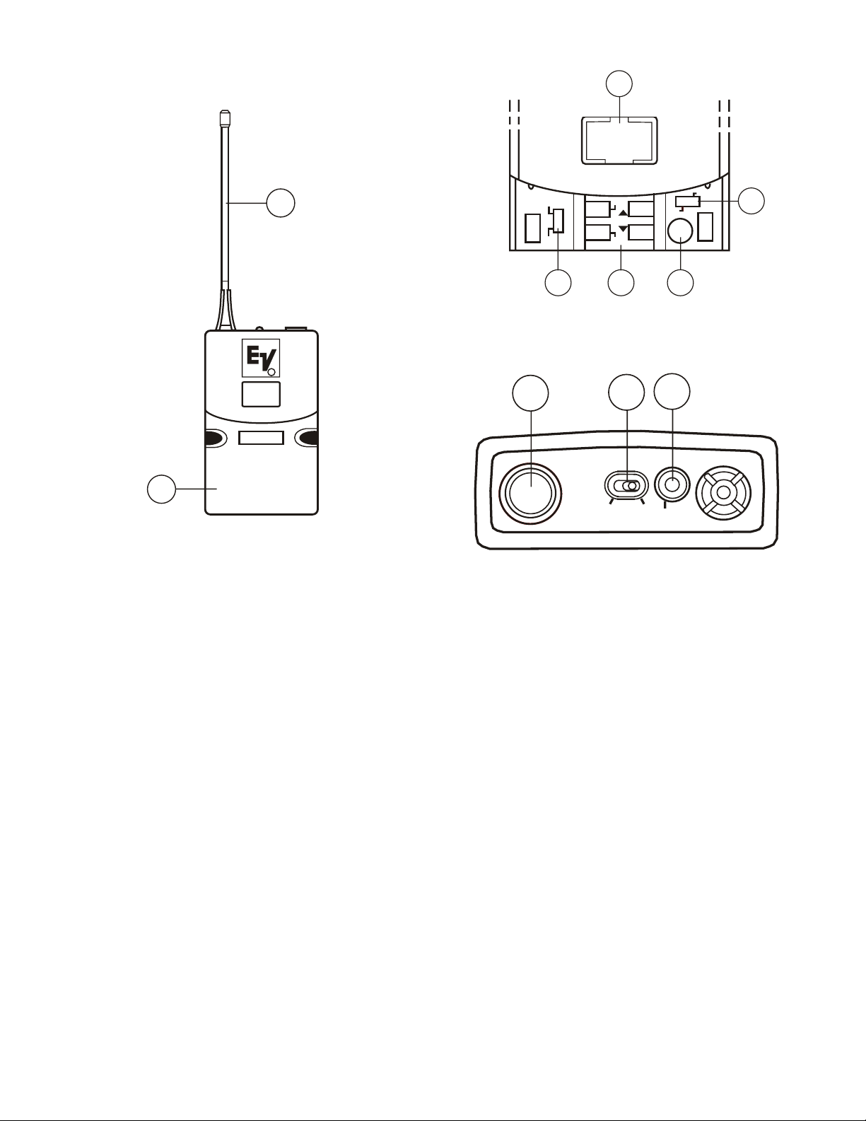
Bodypack Trans mit ter
7 5 5 . 0 5 0
GP C H
High
Normal
Tx
Menu
Set
Gain
Inst
Voice
POWER
OFF
- ON
LOW
BATTERY
7 5 50 5 0
GP CH
CSB-1000
R
5
8
Fig ure 5
Bodypack Trans mit ter
1
4
10
6
Fig ure 6
Con trol View
2 3
Fig ure 7
Top Vie w
11
9
CSH-1000 Con trols, Con nec tors, and In di ca tors
Antenna - flexible 1/4 wave an tenna re movable (re placement part see Section 8)
1.
Power On/Off Switch
2.
Low Bat tery LED In di ca tor
3.
TA4 Au dio Connector
4.
LCD Display (Channel, Fre quency or Battery Level Indication)
5.
Dis play Con trol But tons (Menu/Set/Up/Down)
6.
Belt Clip (Removable and De tachable) not shown
7.
9V Bat tery Compartment
8.
Audio Gain Adjustment
9.
Transmitting RF Power Switch
10.
In stru ment/Voice Switch
11.
3-6
Page 13

Bodypack Trans mit ter Setup
and Op er a tion
1. In stall An tenna. The CSB-1000 is equipped with a de -
tachable an tenna. Screw in the an tenna in cluded with the
system. See the ac cessories sec tion at the end of this man ual for in formation on op tional antennas for the
CSB-1000.
2. In sert Bat tery. Pinch the battery door tabs inward and
pull the door open. In sert a 9V bat tery as in dicated by the
+/- in the holder. (NOTE: The CSB-1000 unique design
allows the battery to be in serted and used re gardless of the
pos i tive and neg a tive ter mi nal po si tion, the in di ca tors are
there for ref erence only).
With battery compartment still open, turn the unit on with
3.
Power switch on the top panel. The low bat tery LED will
light for a second and the dis play will show the battery
level, then the Group and Channel numbers.
4. Change the group and chan nel num bers to match those
displayed on the re ceiver by pressing SET. The Group
number will flash and can be changed with the UP/DOWN
keys. Once the de sired Group number is show ing, press
SET to se lect and the Channel num ber will flash. Se lect
the Channel and press SET again, the flashing will stop
and the chan nel is now set.
8. Ad just ment of the Trans mit ter Au dio Gain - (if nec essary). The transmitter audio gain is factory set at 1/3 of
maximum range, which should be suitable for most applications. For loud or soft speakers/singers a gain adjustment may be nec essary. Have the speaker or singer use the
microphone in a nor mal performance level voice. The Au dio Meter in the main receiver display screen should show
peaks around the -3 dB level. If the meter peaks all the
way to the right or well be low the -3 dB level, adjust the
trans mit ter au dio gain.
To ad just the transmitter gain, gently insert the provided
screwdriver (or other screwdriver) into the adjustment po ten ti om e ter. Gently turn coun terclock wise un til the con trol
stops (the microphone out put is at minimum but not off).
Slowly turn the gain control up (clockwise) while speaking/singing into the microphone or playing the instrument
and the au dio meter shows peaks around -3 dB.
9. In stru ment Gain Ad just ment.
normal. Ad just the transmitter au dio gain if needed. If the
audio is distorted, in sure that the voice/instrument switch
is in the instrument po sition. Very high output instruments
may need ad di tional cord at ten u a tion.
Play the in strument as
5. Change Lock-Out. By pressing and holding the UP and
DOWN ar row keys to gether for 5 seconds, the SET key is
disabled. The MENU button still al lows dif ferent screens
to be displayed. To re activate the SET key, simply press
and hold the UP and DOWN keys again for 5 seconds.
6. Ver ify re cep tion. With the transmitter and re ceiver on and
matching Group and Chan nel, the main receiver display
should be in dicating a RF signal on the bar graph. If the
level meter does not show re ception, make sure the channels are matching and refer to the trouble shooting section.
7. At tach the Mi cro phone or In stru ment.
Mi cro phone: Plug the TA4 end of the microphone cable
into the top panel of the CSB-1000. Speak into the microphone and the Au dio Meter bar graph should indicate au dio signal presence.
Instrument Switch the Voice/Instrument Switch to instrument. Plug in the instrument TA4 ca ble. Play the
instrument and the Audio Meter bar graph on the re ceiver
should in di cate au dio sig nal pres ence.
NOTE: Operating with the transmitter audio gain set as
high as pos sible (without distortion or peaks all the way to
the right end of the me ter) will result in the best performance and high est sig nal to noise ra tio.
10. Trans mitting Power Ad just ment if nec es sary. The
CSB-1000 transmitter has two ra dio transmit power set tings. It is factory set in the NORM position, which will
maximize the number of simultaneous us ers and limit in terference with other wireless de vices. Switching to HIGH
power will maximize range for outdoor and single user ap pli ca tions.
11. Test Per for mance. Go back to Sec tion 3 - Re ceiver Setup
and Op eration step 9 to complete system set up and test.
3-7
Page 14

Trans mit ter Dis play Squence:
Battery Gauge:
Display 3 seconds
Dis playing and Set ting Trans mit ter Fre quency:
To see the current op erating frequency, press MENU at the
Group/Chan nel Screen.
Set ting Cus tom Fre quencies: Select a Group be tween 11u
and 20u and a Chan nel between 1 and 16 (see Group and
Chan nel Set ting above). Press MENU to display the transmitter fre quency. If this Group/Channel is blank you will see
'---.---' on the frequency dis play. (Blank channels also dis play
a '-' af ter the channel number on the Group/Channel screen).
Press SET and use the UP or DOWN but tons to change the
frequency. Press SET to save the new fre quency, or MENU to
quit without saving changes since SET was last pressed.
Group Channel
Press MENU
Frequency Display
Press MENU
Battery Gauge
Press MENU
Bat tery In di ca tor:
Battery condition is displayed on power up. The low battery
LED should flash once to indicate an ac ceptable bat tery. If the
battery is nearly depleated, the low bat tery LED will come on
and stay on. When bat tery voltage is too low for proper microphone op eration, the low battery LED will flash continuously
and the unit will not transmit. You can check battery con dition
at any time by pressing the MENU but ton twice from the
Group/Channel display screen. Battery con dition is also displayed at the re ceiver.
Group and Chan nel Set ting:
Transmitter fre quencies are di vided into 20 Groups of 16 fre quencies (or Channels). Fre quency Groups 1 through 10 are
predefined and cannot be changed. Frequency Groups 11u
through 20u can be set by the user.
Power Switch Disable:
When the Power Switch is disabled, you must move the power
switch to the OFF po sition and then press a con trol key
(MENU, SET, UP or DOWN) to power the unit off.
To en gage a one-time power switch lock: Turn the unit on. Af ter the display shows Group & Channel, quickly turn the
power off and on three times. "On-Loc" will show on the display. A One-time lock dis ables it self the next time the unit is
turned on.
To al ways lock the power switch ON, press and hold SET,
then press UP. "On-Loc" will show on the display.
To dis able Power Lock, press and hold SET, then press
DOWN. "On-Off" will show on the dis play. The unit can now
be turned off with just the power switch.
Firm ware Re vi sion Level:
Hold down MENU for 5 seconds. The pro gram firmware revision number will dis play, fol lowed by the factory pre set fre quency group re vision number.
Quick Setup:
Press and hold the MENU but ton. Turn on the power switch.
Wait un til Group and Chan nel are displayed. Release the
MENU button. Unit is now set to Group 1/Channel 1 with
Group or Channel Flashing.
Fac tory Re set:
WARNING: This will erase any user frequencies stored in
Groups 11u to 20u. From the Group/Channel screen, press
and hold MENU, SET, UP and DOWN until "Clr.All" is displayed on the LCD screen. Unit will restart in Quick Setup
mode.
To set the Group and Chan nel: Press SET at the
Group/Channel display screen. When the Group number be gins to flash, use UP or DOWN to change the Group number.
Press SET to save the new Group setting. When the Chan nel
number be gins to flash, use UP or DOWN to change the
Channel number. Press SET to save the new Channel setting.
Press MENU if you wish to stop without saving.
3-8
Page 15

Main Op er ating Screen
GP CH
1 2 u 0 5
-20 -10 -6 - 3 0 +3
1 3 10 30 100
E V
ON E
Section
4
Receiver Dis play Screens and Functions
Display:
8
1
4
2
5
3
7
Figure 8
Main Op er ating Screen
1. Group Num ber ···················10 fac tory + 10 user de fined
2. Chan nel Num ber ················01 to 16
3. Mi cro phone La bel or Name ·······2 lines x 9 characters - all cap itals
4. Bat terySta tus···················100 to 0 Pct in 20 Pct steps / Flash if low
6
Con trols:
5. Au dio Me ter ····················-30 to +3
6. RF Sig nal Strength···············0 to 300
7. An tenna Di ver sity Sta tus ·········left or right an tenna combinations
8. Edit Lock out Status··············Padlock next to GP in dicates Locked
1. [MENU] goes to next screen
2. [UP] + [DOWN] for 3 sec onds Sets / Re sets Edit Lockout
4-1
Page 16

Group / Chan nel Edit Screen
E d i t MH z 7 2 2 . 2 5 0
Ch a n n e l 1 6
t v c h a n 5 6
B a n d B Gr o u p 1 2 u
Fig ure 9
Group / Chan nel Edit Screen
Dis play:
Con trols:
1. Fre quency Band Des ig na tion ······A or B
2. Group Num ber··················10 fac tory + 10 user de fined
3. Chan nel Num ber ················01 - 16
4. TV Chan nel ····················US TV chan nel the frequency is in
5. Transmit / Re ceive Frequency ·····680.100 - 703.900 MHz A Band (US)
722.100 - 745.900 MHz B Band (US)
798.100 - 821.900 MHz D Band
841.100 - 864.900 MHz E Band
1. [MENU] goes to next screen
2. [UP] + [DOWN] for 3 sec onds Sets / Re sets Edit Lockout
If Edit Mode is not locked out:
[SET]
3.
Starts Edit mode; Group Number be gins flashing
A.
Steps be tween Group Number and Channel Number. Se lected field flashes
B.
to in dicate it can be changed.
Effects change af ter [UP] or [DOWN] have been pressed, then returns you
C.
to Display Mode
[MENU] stops Edit mode without effecting changes since [SET] was last pressed
4.
[UP] or [DOWN] (in Edit Mode)
5.
Increments or dec rements Group Number when flashing
A.
In cre ments or dec re ments Chan nel Num ber when flash ing
B.
[UP] and [DOWN] auto-repeat when the button is held. Auto-repeat starts
C.
after the button has been held for 1 second. Group and Channel have a slow
auto-repeat.
4-2
Page 17

Frequency Edit (User Groups Only)
E d i t MH z 7 2 2 . 2 5 0
Ch a n n e l 1 6
t v c h a n 5 6
B a n d B Gr o u p 1 2 u
Frequency Edit (User Groups Only)
Fig ure 10
Dis play:
Con trols:
1. Fre quency Band Des ig na tion ······A or B
2. Group Num ber··················10 fac tory + 10 user de fined
3. Chan nel Num ber ················01 - 16
4. TV Chan nel ····················US TV chan nel the frequency is in
5. Transmit / Re ceive Frequency ·····680.100 - 703.900 MHz A Band (US)
722.100 - 745.900 MHz B Band (US)
798.100 - 821.900 MHz D Band
841.100 - 864.900 MHz E Band
1. [MENU] goes to next screen
2. [UP] + [DOWN] for 3 sec onds Sets / Re sets Edit Lockout
If Edit Mode is not locked out:
[SET]
3.
Starts Edit mode; Frequency be gins flashing
A.
Steps be tween frequency and channel num ber, se lected field flashes to in dicate change
B.
Effects change af ter [UP] or [DOWN] have been pressed, then returns you to Display Mode
C.
[MENU] stops Edit mode without effecting changes since [SET] was last pressed
4.
[UP] or [DOWN] (in Edit Mode)
5.
In User De fined groups, [UP] or [DOWN] in crements or decrements the fre quency
A.
in 25 kHz in crements
In cre ment or dec re ments chan nel num ber when flash ing
B.
Un de fined fre quen cies are dis played as '---.---'.
C.
[UP] and [DOWN] auto-repeat when the button is held. Slow Auto-repeat starts after the button
D.
has been held for 1 second. If the but ton is held for 16 slow steps, Auto-repeat shifts to fast
Auto-repeat.
4-3
Page 18

Func tions Screen
S o u n d Ch e c k
[ N E X T ]
N a me E n t r y
S e t S q u e l c h
[ N E X T ]
[ N E X T ]
Cl e a r S c a n A l l
Cl e a r S c a n 1 2 u
Cl e a r S c a n B a n d
[ N E X T ]
Co p y Gr o u p 1 2 u
S c r e e n T i me r ON
Cl e a r Gr o u p 1 2 u
[ P R E V I OU S ]
OK ? =[ S E T ] 0 2 X
N E X T 0 4 0 8 1 6
Gr o u p 0 1 0 1 0 5 0 9
P r e v 0 3 X 1 5
CL E A R S CA N
T M
Con trols:
Use [UP] [DOWN] to select
and view other func tions
Use [SET] to start the function
ClearScanTM All
ClearScanTM All searches all de fined fre quency groups for the
ones with the great est num ber of re ceiver channels clear of in terference. Once a group is se lected an ad ditional scan is made
to de termine the best frequencies in the group:
Press [SET] to initiate
Press [MENU] to abort
Af ter scan ning, ClearScan
the most in terference free re ceive chan nels. These clear channels are displayed on the right half of the screen. Busy channels are represented by an X. Press [SET] to place the re ceiver
on this group. ClearScan
channels within the group (see ClearScan
Press [SET] to accept this channel and re turn to the op erating
screen.
The [UP] and [DOWN] but tons may be used to se lect the next
best group/channel and so forth.
Press [MENU] to re turn to the Operating Screen with the receiver set to the Group, Channel and Fre quency it was on
prior to ex e cut ing ClearScan
TM
will display the group that has
TM
then scans to se lect the clear est
TM
.
TM
Current Group).
Fig ure 11
Func tions Screen
Fig ure 12
TM
ClearScan
All
4-4
Page 19

ClearScanTMCur rent Group
OK ? =[ S E T ] 1 5 0 1
N E X T 0 2 1 6
Gr o u p 1 2 u 0 4 0 3 0 9
P r e v 0 5 0 8
CL E A R S CA N
T M
Gr o u p 2 1 s
OK ? =[ S E T ] N e x t
Ch a n . 0 1 7 2 8 . 4 7 5 MH z
P r e v
CL E A R S CA N
T M
S c a n n i n g B a n d
ClearScanTMCurrent Group scans channels within the cur rently se lected frequency group and displays the chan nels that
are clear of in terference.
Press [SET] to initiate
Press [MENU] to abort
After scanning the cur rently se lected group, ClearScan
TM
will
display the chan nels that are free of in terference. These clear
channels are displayed on the right half of the screen. The
channels are ranked according to noise; the channel with the
least amount of in terference is presented first.
The [UP] and [DOWN] but tons may be used to se lect a different clear channel within the cur rently se lected group.
Press [SET] to place the re ceiver on the cur rently se lected
channel and re turn to the Operating Screen.
Press [MENU] to re turn to the Operating Screen with the receiver set to the Group, Channel and Fre quency it was on
prior to ex e cut ing ClearScan
TM
.
ClearScanTMBand
ClearScanTMband con tin u ously scans all fre quen cies within
the bandwidth of the re ceiver. The scan is started at the frequency the receiver is on and pro ceeds in 200 kHz in crements
on ei ther side un til the whole band is scanned. The scan is repeated un til ended by the user.
Press [SET] to initiate
ClearScan
Fig ure 13
TM
Cur rent Group
Each fre quency is scanned con tinuously within the band; the
highest read ing on each fre quency is stored to give a
worse-case read ing as long as the scan is be ing done.
Pressing [SET] ends the scan. Af ter scanning, ClearScan
TM
places the 16 best frequencies in the band into 'scanned' group
21s. This group is stored to prevent accidental era sure. The
best fre quency is placed at channel one and displayed.
The [UP] and [DOWN] but tons may be used to se lect the next
clear chan nel at least 200 kHz above or be low the currently
dis played fre quency.
Press [SET] to ac cept cur rently se lected fre quency and re turn
to the Operating Screen.
Press [MENU] to re turn to the Operating Screen with the receiver set to the Group, Channel and Fre quency it was on
prior to ex e cut ing ClearScan
TM
.
4-5
Fig ure 14
ClearScan
TM
Band
Page 20

Edit Mi cro phone La bel/Name
N a me J K L MN OP QR S
- - - - - - - - - - 0 1 2 3 4 5 6 7 8 9
E n t e r A B C D E F GH I
- - - - - - - - - - T U V WX Y Z - . !
S o u n d
Ch e c k
-20 -10 -6 - 3 0 +3
1 3 10 30 100
Co u n t 0 0
S QU E L C H
T ON E S OF F
Dis play:
Mi cro phone La bel/Name
1.
Char ac ter Set
2.
Con trols:
[MENU] goes to next screen.
1.
[SET] (First time) enters Edit Mode:
2.
Starts flash ing first char acter in Name/La bel
A.
Flashes first char acter of the Name/La bel in the
B.
Char ac ter Set
[UP] flashes the next char acter in the Character Set and
3.
displays the se lected char acter at the cur rent cursor position in the Name field.
[DOWN] flashes the previous character in the Character
4.
Set and displays the se lected char acter at the cur rent cursor
position in the Name field.
[SET] saves the cur rently se lected char acter into the current
5.
character po sition of the Name/La bel field and ad vances to
the next character po sition of the Name/La bel field.
Fig ure 15
Edit Mi cro phone La bel/Name
[MENU] saves the Name/La bel as dis played on the screen
6.
and goes back to Dis play Mode on this screen.
Sound Check Screen
Dis play:
Bat tery Sta tus
1.
Peak Au dio level held while
2.
screen is displayed
Range of RF Signal Strength
3.
Squelch Break Counter
4.
Set Squelch Threshold:
CAUTION: SEE PAGE 3-3 STEP 11A.
Dis play:
Press[SET]
1.
Con trols:
[SET] dis ables tone squelch and enables edit mode (allows
1.
squelch level adjustment). Squelch bar will flash in edit
mode. Tone Squelch is disabled.
[UP] raises the squelch threshold
2.
[DOWN] low ers the squelch threshold
3.
[SET] saves the new threshold
4.
[MENU] (From edit mode) re stores threshold to the setting
5.
just after the last time [SET] was pressed
Con trols:
1.
2.
3.
[MENU] goes to next screen
[SET] clears screen dis play vari ables
and re starts Sound Check
[UP] turns on the Count Beep ( ),
[DOWN] turns the beep off ( ).
4-6
Fig ure 16
Sound Check Screen
Fig ure 17
Squelch Threshold
Page 21

Copy Group
t o Gr o u p 1 4 u
Ch 0 1 MH z 7 2 3 . 4 0 0
Co p y Gr o u p 1 2 u
S c r e e n T i me r ON
Cl e a r U s e r Gr o u p ?
1 2 u
Selecting the Copy Group will copy the currently se lected
group to the first un used User Group.
Press [SET] to accept the group and place the unit into the
Frequency Edit Screen (User De fined groups only) for ed iting.
Press [UP/DOWN} to select a different user group.
Press [MENU] to re turn radio to its pre vious state.
Screen Timer
Selecting the Screen Timer allows enabling/disabling of
screen timer. With timer en abled the screen will re turn to Op erating screen if no key is pressed within five minutes.
NOTE: Timer is not active in the sound check screen.
Press [UP/DOWN] to turn timer ON/OFF.
Press [SET] to setting.
Press [MENU] to re turn radio to its pre vious state.
Clear Group
Clear Group will delete all channels within the selected group.
Press [SET] to clear the group, and place the unit in the
Group/Channel edit screen with Group=1, Channel=1. Group
will be flashing to enable the se lection of a new group.
Press [MENU] to re turn radio to the op erating screen.
Fig ure 18
Copy Group
Fig ure 19
Screen Timer
Lock out
Press and hold [UP] + [DOWN] for 3 seconds. The unit will
not allow editing of any of the user variables: Group, Chan nel,
Frequencies, Squelch, Name, and ClearScan
TM
.
Mas ter Re set
Press and hold [Menu + Set + Up + Down] to place the unit
into its factory con figuration: Group 1, channel 1, user groups
cleared, default squelch set ting.
Transmitter On/Off Lock Out
There are two On/Off lock out modes available, One Time and
Everytime.
One Time: Cycling the power switch 3 times in un der 3 seconds and On-Loc will be displayed for a second and then re turn to nor mal op eration. The power switch alone will no
longer turn the unit off. To turn the unit off, put the power
switch in the off po sition (On-Loc will be displayed) open the
battery door and press [Menu], [Set], [Up] or [Down] and the
unit will power down. The next time the unit is pow ered on
the power switch will operate normally.
Fig ure 20
Clear Group
Everytime Use: With the unit on and op erating in the normal
mode, press and hold [Set] and press [Up]. On-Loc will be
displayed and the power switch alone will no lon ger turn the
unit off. To turn the unit off, put the power switch in the off
position (On-Loc will be displayed) open the battery door and
press [Menu], [Set], [Up] or [Down] and the unit will power
down. The next time the unit is pow ered on the On-Loc func tion will still be on. To en able the power switch, press and
hold [Set] and press [Down] (On-Off will be displayed).
4-7
Page 22

4-8/Blank
Page 23

Section
5
Guide lines and Rec om men da tions
for Best Performance
Com pat i bil ity
The transmitter and receiver must be of the same fre quency
band and set to the same group and channel in or der to work
to gether. The CSR-1000 is available in two fre quency bands,
A and B. The band in formation is available in the
Group/Channel edit screen on the re ceiver, the bot tom la bel on
the handheld transmitter, and on the back panel la bel on the
bodypack.
Using Mul ti ple Wire less Sys tems
If two or more CSR-1000 systems and/or other UHF/VHF
wireless systems are be ing used in the same location, proper
fre quency co or di na tion is nec es sary to avoid in ter fer ence. All
channels in the CSR-1000 fac tory set groups are de signed to
work to gether, so if chan nels from just one group are used no
further co ordination is required. Con tact your dealer or Telex
for as sistance if you are planning more systems or us ing the
CSR-1000 with other wireless equipment.
IM POR TANT NOTE; For 12 or less frequencies to be used
together, se lect all frequencies from only one of group 1-6.
Normal power will sometimes work more effectively than
high power when us ing larger numbers of frequencies.
IM POR TANT NOTE: Groups 7, 8, 9, and 10 have 16 channels and are marked with an N (7N). These groups re quire the
transmitters to be in the NORMAL transmit power set ting to
work to gether. The N groups will always be displayed after
groups 1-6 and any user de fined groups no matter how many
channels are free. If you need to use more than 12 systems at
one time, scroll down to the N groups and use the clearest
group with Nor mal transmit power.
Po ten tial Sources of In ter fer ence
There are many po tential sources of in terference for your
wireless system. Any electronic product that contains digital
cir cuitry including dig i tal sig nal pro ces sors (reverb/multi-effects units), elec tronic keyboards, digital lighting
con trol lers, CD and DVD play ers, and com puters, all emit RF
energy that can ad versely affect the performance of your wireless sys tem. It is al ways best to place the re ceiver as far away
as pos sible from these de vices to minimize po tential problems.
An a log and Dig i tal Tele vi sion sta tions can also in ter fere with
your wire less sys tem. The CSR-1000 is designed to op erate
over 24 MHz of RF band width, which cov ers four TV chan nels. The factory pre sets on the CSR-1000 are optimized for
conditions where one or pos sibly two of the four stations are
covered in your area. If three of the four stations are used in
your area, it will se verely limit the number of sys tems that will
operate to gether and you should be us ing a different band.
Bat tery Rec om men da tions
Fresh 9-volt al ka line bat ter ies from a qual ity man u fac turer
will yield the best performance from your CSR-1000 transmitters. Re chargeable 8.4-volt Ni-Cad bat teries can be used but
will result in much shorter operation time.
When the transmitters are turned on, the red battery LED will
flash once if the battery is good. If the light does not light or
stays lit con tinuously, the bat tery is weak or dead. If the light
comes on dur ing use, the bat tery is weakening and should be
replaced as soon as possible. If sound quality de grades dur ing
use, it may be the re sult of a weakening bat tery.
Mul ti ple Sys tems and Ad vanced
ClearScan
Because all of the chan nels in the factory set groups are com pat i ble Ad vanced ClearScan
systems quickly and with con fidence. When setting up more
than one system, set up the first system us ing the ClearScan
All func tion. Once the work ing Group has been es tablished,
leave the first transmitter on, set the next receiver Group to the
working Group and run ClearScan
the next clearest channel in that group. Set the transmitter to
match, leave it on and repeat un til all the sys tems are set up. If
you run out of clear channels in one group but need to set up
more sys tems, contact your dealer or Telex for as sistance in
choos ing ad di tional fre quen cies.
TM
TM
can be used to set up multiple
TM
Group. This will provide
TM
Caution: The bat tery level in dicators, on the trans mitters
and receiver dis plays, are based on the use of al kaline bat teries. Use of other bat tery types will result in false readings on these indicators although the low bat tery LED on
the trans mit ters will op er ate nor mally.
Receiver and An tenna Placement
Do not place the re ceiver near a large metal ob ject or surface.
Locate the re ceiver as close as pos sible to the area where the
transmitter will be used. Ideally, position the receiver/antennas
within sight of the transmitter. When us ing mul tiple systems,
do not allow antennas to cross or touch each other. For best results with multiple receivers, use an AD-450 antenna splitter
(see Sec tion 8).
5-1
Page 24

5-2/Blank
Page 25

Section
6
Trou ble Shoot ing Guide
Prob lem
No au dio and no display on the
re ceiver
No au dio and no RF signal indicator
on the receiver display
No Au dio with good RF signal indicator but no (or low) Au dio indicator on
the re ceiver dis play
No (or low) Au dio with good RF signal and Au dio indicators on receiver
dis play
Pos si ble Causes
Receiver is off
Trans mit ter is off
Transmitter is on a different channel
No (or dead) bat tery in transmitter
Faulty bat tery contacts
Mi cro phone not connected
Low gain setting on the transmitter
Receiver au dio output cable is damaged or disconnected
Gain not sufficient on
mixer/preamp/amp in put or it is muted
So lu tions
Make sure that the power supply is
properly connected and the on/off but ton is in the on po sition
Turn on transmitter power switch
Match the transmitter group and channel to the one dis played on the re ceiver.
Insert fresh bat tery in transmitter
Clean and or bend contact
Check the TA4F con nector on the
bodypack or the detachable microphone el e ment con nec tion on the
handheld
In crease the trans mit ter gain
Connect, re pair or re place ca ble
Increase gain on mixer or un-mute
the input
Dis torted au dio sig nal
Interference
Receiver output too low (1/4" out put)
Transmitter au dio gain too high
Receiver output too high (1/4" out put)
Loud in strument or au dio source
Battery level low in transmitter
An other CSR-1000 sys tem in the installation is on the same channel or the
signals are mix ing
Another wireless prod uct in the area is
on the same fre quency or the sig nals
are mixing
6-1
Increase the au dio output setting
Decrease the transmitter gain set ting
Decrease the re ceiver output set ting
Change the bodypack au dio mode
switch to Instrument set ting
Insert fresh bat tery in transmitter
Make sure all the chan nels in use are
from the same group. Use ClearScan
to se lect the clear est group. If more
channels are needed call Telex at
800-392-3497 for coordination help
Use ClearScan
ing frequency. If prob lems per sist, call
Telex at 800-392-3497 for co ordination
help
TM
to change the op erat-
TM
Page 26

Trou ble Shoot ing Guide (con tin ued)
Prob lem
Interference (continued)
Short range or drop-outs
Pos si ble Causes
Receiver is too close to digital sig nal
pro ces sor or sim i lar de vice
Strong elec tro mag netic field from
stage lighting or other source near the
transmitter or receiver, which may be
producing RF noise at or near the op er at ing fre quency
RF re flec tive metal ob sta cles be tween
the trans mitter and receiver
Poorly ori ented beltpack an tenna
Faulty re ceiv ing an tenna sys tem
Application requires high transmitter
out put
So lu tions
Move the receiver to a different
location
Use ClearScan
ing frequency. Repair or re move the
source of in terference. Move the re ceiver to a different lo cation.
Move the ob stacles, or reposition the
re ceiver/an ten nas
Check the antenna connection and re ori ent the bodypack so the an tenna is
vertical (up and down) and facing the
re ceiver, if pos si ble.
Check all an tenna connections and reposition to be in line-or-sight with the
trans mit ter
Switch the transmitter to the high
power setting (see page 3-6)
TM
to change the op erat-
Can't change settings on re ceiver or
transmitter
Can't change fre quency setting for a
channel
Bodypack or Handheld transmitter
will not turn off, display says On-Loc
Lockout feature is enabled
Channel not in a user de finable group
On/Off lockout is engaged
6-2
Disable lock out (see pages 3-3, 3-5,
and 3-7)
Change to a user de finable group
(see page 3-2)
Put the on/off switch in the off position
and press one of the pro gramming buttons (see page 4-7)
Page 27

Section
Technical Specifications
CSR-1000 Receiver
Spec i fi ca tions
Over all
Re ceiver Type .................................................Syn the sized PLL
Frequency Range (RF) .....................................A Band 680 - 704 MHz
B Band 722 - 746 MHz
D Band 798 - 822 MHz
E Band 841 - 865 MHz
7
Number of Chan nels ...................................... >900 pos sible chan nels
Programmable in 25 kHz steps
Mod u la tion ................................................+/- 40 kHz deviation
Di ver sity .......................................DSPPosi -Phase
RF Sen si tiv ity .........................................<0.8 μV for 12 dB SINAD
Im age Re jec tion .......................................................>60 dB
Squelch...................................................Tone plus Am plitude
Ul ti mate Quieting ....................................................> 100 dB
Power Re quire ments ........................................12 VAC, 750mA max
Operating Temperature.................................-7° to 49° C (20° to 120° F)
Di men sions ....................................1.72 in. H x 7.50 in. W x 8.38 in. D
43.69 mm H x 190.50 mm W x 212.85 mm D
TM
True Di versity
7-1
Page 28

CSR-1000 Re ceiver
Spec i fi ca tions (con tin ued)
Au dio Pa ram e ters
Fre quency Re sponse ...........................................30 - 15 kHz +/- 2dB
Bal anced Out put ..................................-20dBV (max @ 40 kHz de viation)
Un bal anced Out put ..................................adjustable 8 mV to 0.755V RMS
Dis tor tion .......................................<0.5% (ref 1kHz, 40kHz de viation)
Sig nal-to-Noise Ra tio....................................................>110 dB
Dy namic Range ........................................................>100 dB
Trans mit ters CSB-1000 and CSH-1000
RF Out put..................................................Nor mal 5 mW Typ i cal
High 50 mW Typ i cal
Mi cro phone Head RC767A..............ElectroVoice N/D 767a cardioid N/DYM dynamic
Mi cro phone Head RC510 .......................ElectroVoice RE 510 cardioid con denser
Stan dard Lavalier Mi cro phone .............................Telex ELM-22 MicroMini
TM
Omni-Directional Condenser
TA4F Con nec tor Wiring ...............................Pin 1: Ground; Pin 2 Mic In put;
Pin 3: +5V bias; Pin 4: +5V bias
through a 3kW re sis tor
Au dio Gain Ad just ment Range ......................................Handheld 26 dB
Bodypack 40 dB
Power Re quire ments.........................................9 Volt Al kaline Bat tery
Bat tery Life (Typ i cal) ..........................8-10 hours with 9-Volt Al kaline Typical
Bodypack An tenna ............................................De tach able 1/4 wave
Handheld An tenna ...............................................In ter nal 1/2 wave
Di men sions (Handheld) .............................................10.54 in. Long
26.8 cm Long
Di men sions (bodypack) .............................3.8 in. H x 2.38 in. W x 0.92 in. D
96.5 mm H x 60.5 mm W x 23.4 mm D
7-2
Page 29

FCC IN FOR MA TION
The TELEX Re ceiver CSR-1000 is au thorized un der Part 15 of the Fed eral Com munication Com mis sion.
The Telex CSB-1000 and CSH-1000 Transmitters are type Ac cepted un der United States
Fed eral Com mu ni ca tions Com mis sion Part 74.
Licensing of Telex equip ment is the user’s responsibility and licensability de pends
upon the user’s clas si fi ca tion, user’s ap pli ca tion, and fre quency se lected. Telex
strongly urges the user to con tact the ap pro pri ate tele com mu ni ca tions au thor ity for
any de sired clar i fi ca tion.
CAU TION: Any changes or mod ifications made to the above equipment could void the
user’s au thority to op erate the equipment.
7-3
Page 30

7-4/Blank
Page 31

Section
Ac ces sories and Parts
MODEL No. Or der No.
1/4 Wave Rx An tenna (A/B) ANU-14 879010
1/4 Wave Rx An tenna (D/E) 879010-1
1/2 Wave Rx An tenna (A) CLA-5 (Green) 870658-5
1/2 Wave Rx An tenna (B) CLA-6 (Or ange) 870658-6
1/2 Wave Rx Antenna (D + E) CLA-8 (Pur ple) 870658-8
1/2 Wave An tenna Bracket AB-2 71138000
Antenna/Power Dis tribution (A, B, D, E) APD4 APD4 (A + B Band)
APD4-1 UK (E Band)
APD4-1 EUR (D Band)
Ter mi na tion Plug for APD4 TP-2 650095
8
Di rec tional Rx An tenna (A, B, D, E) LPA-500 (450-900 MHz) LPA 500
Co ax ial An tenna Ca ble CXU-25 71151025
CXU-50 71151050
CXU-75 71151075
CXU-100 71151100
1/4 Wave Bodypack Tx An tenna (A) AN-Flex A (Green) 879220-4
1/4 Wave Bodypack Tx An tenna (B + D) AN-Flex B + D (RED) 879220-5
1/4 Wave Bodypack TX An tenna (E) AN-Flex E (Blue) 879220-6
1/4 Wave Super-Flex Tx An tenna (A) AN-Sflex A (Green) 879538-4
1/4 Wave Super-Flex Tx An tenna (B + D) AN-Sflex B + D (Red) 879538-5
1/4 Wave Super-Flex Tx An tenna (E) AN-S flex E Blue 879538-6
Bodypack Pouch WP-1000 879553
Strip Connector Mating Block SCB-1 640156
Gui tar Cord MAC-G2 879526
767a Dy namic Head for CSH-1000 RC767A 71837000
RE510 Con denser Head for CSH-1000 RC510 71839000
8-1
Page 32

8-2/Blank
Page 33

Section
Cus tomer Service
CUS TOMER SER VICE IN FOR MA TION
If your re ceiver or transmitter should need ser vicing un der the warranty, please contact:
9
North America
Cus tomer Ser vice De part ment
TELEX COM MU NI CA TIONS, INC.
8601 East Cornhusker High way,
Lincoln, Ne braska 68507-9702 U.S.A.
Phone: (402) 467-5321
Tech ni cal As sis tance: 800-392-3497
(U.S. and Can ada only)
All claims of de fect or
items for ser vice, you must pro vide date and proof of pur chase, such as a copy of the
sales re ceipt, to establish war ranty. A let ter should be in cluded outlining all symptoms
and claimed de fects. In formation on how the equip ment was in stalled and used is very
helpful. Please in clude your phone num ber and re turn ad dress in case our ser vice tech nicians need to con tact you.
Units that have been mod ified can not be ac cepted for re pair.
Include all in formation re quested by the Service De partment. Then pack the unit as fol lows:
short age should be sent to the above ad dress. When re turning
Eu rope
Telex EVI Au dio GmBH
Hirschberger Ring 45
D-94315 Straubing
Ger many
Tel: +49 (0) 9421 706 0
Fax: +49 (0) 9421 706 350
Check the unit to see that all parts and screws are in place. Then wrap it in heavy pa per
or put it in a plas tic bag. If the original car ton is not avail able, place the unit in a strong
carton that is at least six inches big ger in all three di mensions than the unit. Fill the
carton equally around the unit with re silient pack ing ma terial (shredded pa per, foam,
etc.). Seal it with gummed pa per tape, tie it with a strong cord, and ship it by prepaid
express, United Par cel Ser vice or in sured par cel post to the Telex Ser vice De partment.
It is very im portant that the ship ment be well-packed and fully in sured. Dam age claims
must be set tled be tween you and the carrier and this can de lay re pair and return of the
unit to you.
Telex re serves the right to make changes in design and im provement on its prod uct
without as suming any ob ligation to in stall the same on any of its prod ucts pre viously
manufactured. Fur ther Telex re serves the right to ship new and/or im proved prod ucts
which are sim ilar to the form, fit and func tion of prod ucts orig inally or dered.
For other office lo cations see www.electrovoice.com
9-1
Page 34

9-2/Blank
Page 35

Section
10
Limited Warranty
Limited Warranty
TELEX Communications, Inc. (”Telex”) war rants to the user, who orig inally pur chased the serialized
product de livered with this card, that the product will be free from de fects in material and workmanship for the fol lowing pe riods af ter such date of pur chase. Ma terial 36 months, work manship 36
months. Mi cro phones, ear phones, neckloops, ca bles & con nectors are war ranted for ninety days. Telex
will, at its op tion, re pair or replace free of charge such de fective prod ucts sub ject to the fol lowing con di tions:
1. Delivery of the prod uct or parts post age pre paid to the Telex/EV dealer, au thorized service fa cility or fac tory.
2. Determination by Telex that a de fect ex ists and is cov ered by limited war ranty. De fects due to al teration, re pair by un authorized persons, in sertion of non-Telex parts, mis use, ac cidental dam age, use of
the equip ment for pur poses other than those for which it was de signed, and the like, are not cov ered
by this limited war ranty and re pairs thereof will be sub ject to nor mal ser vice charges.
3. Repairs and replacement parts are cov ered un der this limited war ranty only for the un expired term of
the orig i nal lim ited war ranty.
4. Products pur chased from un authorized dealers are not war ranted.
5. You must fill out and re turn the product war ranty card to reg ister the pur chase date of serialized
items. A copy of the bill of sale show ing the date of pur chase must ac company all war ranty work.
THIS LIMITED WARRANTY IS EX PRESSLY IN LIEU OF ANY EX PRESS OR IM PLIED WARRANTY, IN CLUDING ANY IM PLIED WARRANTY OR MER CHANTABILITY OR FIT NESS
FOR A PARTICULAR PUR POSE WHICH EX TENDS BE YOND THE TERM HEREOF. THE
REMEDIES PRO VIDED BY THIS LIMITED WARRANTY ARE THE ONLY REM EDIES AVAILABLE TO ANY PER SON. NO PER SON HAS ANY AU THORITY TO BIND TELEX TO ANY
REPRESENTATION OR WARRANTY OTHER THAN THOSE PRO VIDED BY THIS LIMITED
WARRANTY. TELEX SHALL NOT BE LI ABLE FOR ANY IN CIDENTAL OR CON SEQUENTIAL DAM AGES CAUSED BY FAILURE OR OTH ERWISE OF THE PRO DUCT.
Some states do not al low ex clu sions or lim i ta tions of in ci den tal or con se quen tial dam ages or lim i ta tions on how long an im plied war ranty lasts, so the limitations or ex clusions herein may not ap ply to
you. This war ranty gives you spe cific le gal rights, and you may also have other rights which vary
from state to state and country to coun try.
10-1
Page 36

10-2/Blank
Page 37

TELEX COM MU NI CA TIONS, INC.•12000 Port land Ave. South, Burnsville, MN 55337.
PN 803333 Rev A June 2004 Made in U.S.A.
 Loading...