

Electrolux ZEBF250W, ZEBF262W, ZEBF290W, ZEBF290SI Service Manual
SERVICE MANUAL
REFRIGERATION
© ELECTROLUX HOME PRODUCTS S.p.A. Publication no.
Spares Operations Italy 599 35 61-05
Corso Lino Zanussi, 30 021218
I - 33080 PORCIA / PN (ITALY) ITZ/SERVICE/AA
Fax +39 0434 394096
NOFROST
REFRIGERATORS
with electronic
timer

NOFROST REFRIGERATORS WITH ELECTRONIC TIMER 2/29

NOFROST REFRIGERATORS WITH ELECTRONIC TIMER 3/29
CONTENTS
1. INTRODUCTION........................................................................................................................................................ 5
2. REFRIGERATION CIRCUIT ..................................................................................................................................... 7
3. ELECTRIC WIRING................................................................................................................................................... 8
4. FUNCTIONAL DIAGRAM ......................................................................................................................................... 9
5. OPERATION ............................................................................................................................................................ 10
5.1 NORMAL............................................................................................................................................................. 10
5.2 NORMAL WITH FIRST SWITCHING ON OR POWER FAILURE ................................................................... 11
5.3 DEFROSTING .................................................................................................................................................... 12
5.4 NTC SENSOR MALFUNCTIONING..................................................................................................................13
6. COMPONENTS........................................................................................................................................................ 14
6.1 CONTROL PANEL : ........................................................................................................................................... 14
6.2 REFRIGERATOR COMPARTMENT :............................................................................................................... 14
6.3 FREEZER COMPARTMENT : ........................................................................................................................... 15
6.4 COMPRESSOR COMPARTMENT : ................................................................................................................. 16
6.5 ZCP TERMINAL BOARD ................................................................................................................................... 17
6.6 ELECTRONIC BOARD ...................................................................................................................................... 18
7. ACCESSIBILITY ...................................................................................................................................................... 21
7.1. ACCESS TO CONTROL PANEL ...................................................................................................................... 21
7.2. ACCESS TO REFRIGERATOR COMPARTMENT ......................................................................................... 23
7.3. ACCESS TO FREEZER COMPARTMENT ..................................................................................................... 24
8. TROUBLESHOOTING ............................................................................................................................................ 26
8.1 DRAIN CIRCUIT: ................................................................................................................................................ 26
8.3 FAILED DEFROSTING: ..................................................................................................................................... 27
8.4 BURN OUT LAMP: ............................................................................................................................................. 27
8.5 MANUAL DEFROSTING PROCEDURE........................................................................................................... 28

NOFROST REFRIGERATORS WITH ELECTRONIC TIMER 4/29

NOFROST REFRIGERATORS WITH ELECTRONIC TIMER 5/29
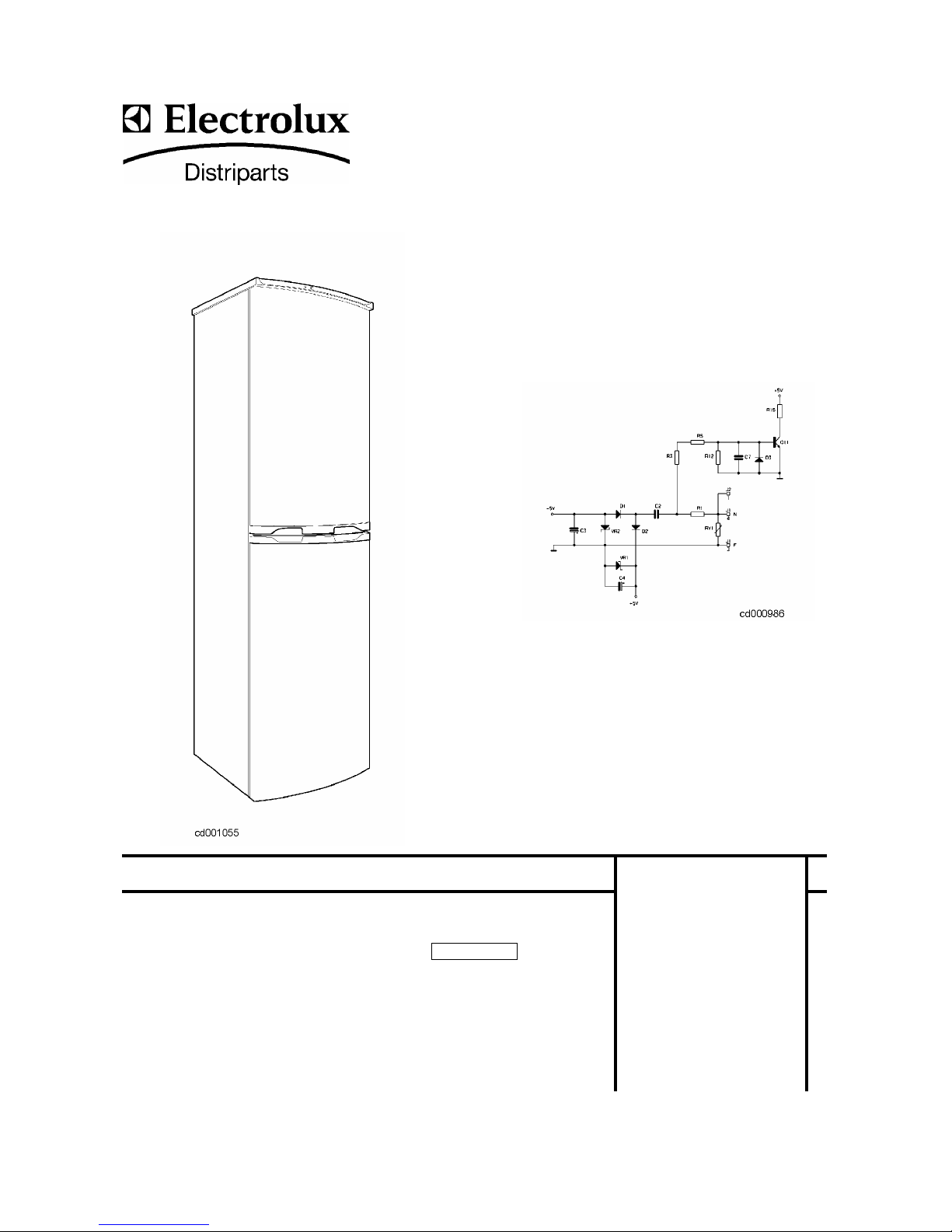
1. INTRODUCTION
This manual describes the NOFROST models WITH ELECTRONIC TIMER.
These models differ from the previous (see SM 599356104) as they do not feature the electromechanical timer
because an electronic timer has been incorporated in the control and power board called ERF1050-01.X (where
X represents a variant of the board).
The three basic models differ only for the volume:
260 litres (ex C9, pnc 925886…), 262 litres (ex C10, pnc 925887…) and 290 litres (ex C11, pnc 925888…).
pnc Date Model Brand
92588670000 20021220 672.700 2/40032 Privileg
92588670100 20030606 CZC16/9FA Zanussi - Electrolux
92588670300 20030321 ZEBF250W Zanussi - Electrolux
92588770000 20030418 ZEBF262W Zanussi - Electrolux
92588870000 20021220 672.694 7/40033 Privileg
92588870100 20030418 ZEBF290W Zanussi - Electrolux
92588870200 20030606 ZEBF290SI Zanussi-Electrolux
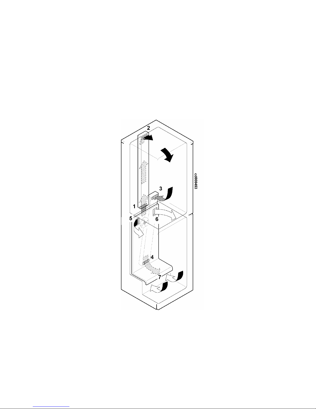
The NOFROST refrigerators consist of a refrigerator compartment A and a freezer compartment B.
The cold, produced by the battery evaporator in the freezer compartment, is then distributed in the refrigerator
and freezer compartments by the fan placed over the battery.
NOFROST REFRIGERATORS WITH ELECTRONIC TIMER 6/29
REFRIG ER AT OR CO MPARTMENT (A)
The air is pushed by the fan down the foam duct at the bottom of the compartment: it enters by nozzle 1 and
comes out of nozzle 2. Manual flap C enables to regulate the flow of cold air and therefore the temperature
inside the compartment.
The thermostat bulb is located inside the flap and reacts both to the air temperature of the air coming out of
nozzle 2, and to the air temperature inside the refrigerator compartment.
The air returns to the air compartment through the foam duct at the bottom of the compartment, entering from
nozzle 3 and leaving from nozzle 4.
FREEZER COMPARTMENT (B)
The cold air is pushed into the compartment by the fan through the two nozzles 5 and 6. After circulating, the air
is rechannelled to the evaporator battery through opening 7, under the protection panel.
NOFROST REFRIGERATORS WITH ELECTRONIC TIMER 7/29
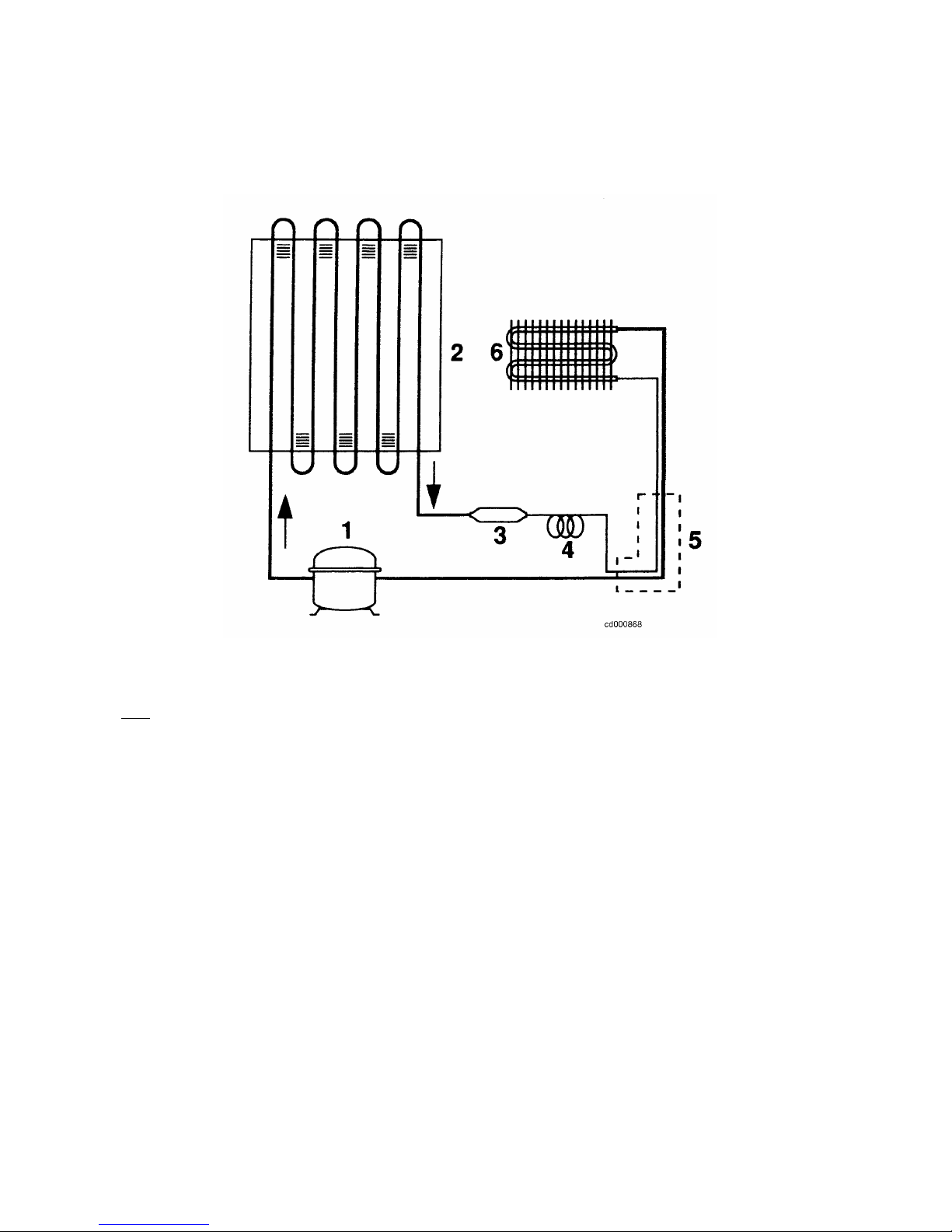
2. REFRIGERATION CIRCUIT
Key:
1. compressor
2. condenser
3. filter
4. capillary
5. heat exchanger
6. battery evaporator

NOFROST REFRIGERATORS WITH ELECTRONIC TIMER 8/29
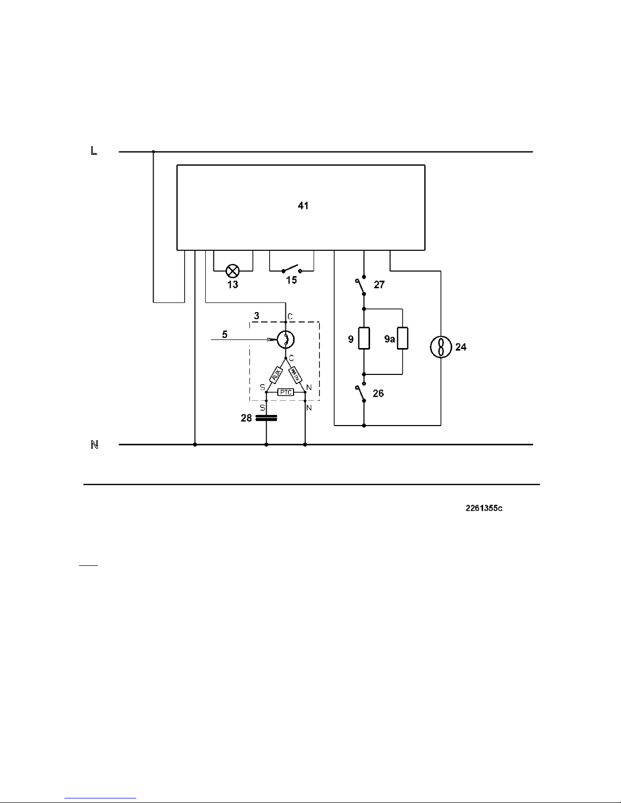
3. ELECTRIC WIRING
( check the specific diagram for each model! )
Key:
1. ZCP terminal board a. yellow-green
3. terminal board of freezer compressor b. brown
5. motor protector d. white
9. stylus defrosting heater c. blue
9a. armoured defrosting heater e. black
13. refrigerator lamp
15. light switch
24. battery fan
26. safety thermal switch (+40 °C )
27. defrosting cut-out switch (+10°C)
28. running capacitor (only for the models which feature it)
41. electronic thermostat assembly with timer
56. NTC sensor
NOFROST REFRIGERATORS WITH ELECTRONIC TIMER 9/29
4. FUNCTIONAL DIAGRAM
( check the specific diagram for each model! )
Key:
1. ZCP terminal board a. yellow-green
3. terminal board of freezer compressor b. brown
5. motor protector d. white
9. stylus defrosting heater c. blue
9a. armoured defrosting heater e. black
13. refrigerator lamp
15. light switch
24. battery fan
26. safety thermal switch (+40 °C )
27. defrosting cut-out switch (+10°C)
28. running capacitor (only for the models which feature it)
41. electronic thermostat assembly with timer
56. NTC sensor
 Loading...