

Electrolux EFME627UTT, EFMG427UIW, EFMG627UIW, ELWADREW5271, ELWADRGT5273 Data Sheet
...
Dryer Tech Data Sheet
1
This information is intended for Qualified Technicians Only.
TABLE OF CONTENTS
Dryer Tech Data Sheet ........................................................................... 1
Diagnostic Mode Tests/Demo Mode ...................................................... 2
Dryer Error Codes .................................................................................. 3
Wiring Diagrams .................................................................................. 10
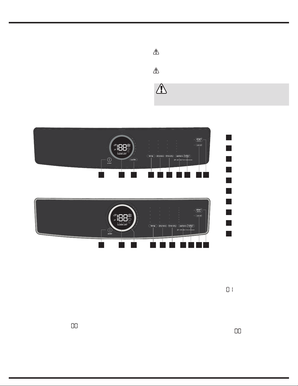
Push Button Cycle Select Dryer User Interface
2 71 63 854 9
Safety items throughout this manual are labeled with a WARNING or
CAUTION based on the risk type as described below:
WARNING
CAUTION
This symbol alerts you to situations that may
cause serious body harm, death or property
damage.
This symbol alerts you to situations that may
cause bodily injury or property damage.
CAUTION
Unless otherwise directed, disconnect electrical current before
servicing.
power
1
cycle status display
2
cycle selector
3
temperature
4
10
dryness (dry level)
5
Rotary Dial Cycle Select Dryer User Interface
2 71 63 9854 10
Entering Diagnostic Mode:
1. Press power and look for console light up.
2. Rotate cycle selector ring (on some models) or repeatedly press
cycle button (on other models) to set cycle to normal.
3. Press the start button.
4. Power off machine by pressing the power button.
5. Power on machine by pressing the power button again.
6. Within 10 seconds, simultaneously hold temp + select (set) buttons together for 3 seconds.
7. Diagnostic Mode is active when LED’s start blinking in sequence.
This is the pre-test position “ ”, which tests the lights and buttons.
time dry (dry time)
6
options
7
select (set)
8
cancel
9
start / pause
10
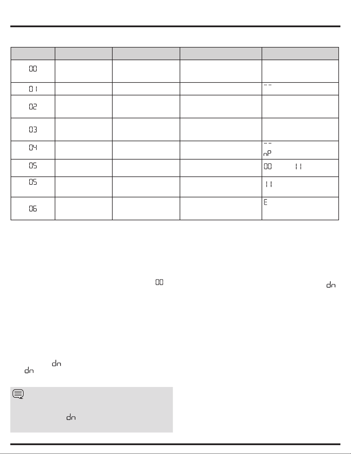
Scrolling through Diagnostic Mode tests:
Tests are selected by using the same method to select cycles.
Diagnostic Mode Tests Table.
To begin, press and hold the cycles button for 2 seconds. The unit
will advance to the first test; and flash “ “ on the display.
Press the cycles button to advance to the following test. Press the
temp button to go back to the previous test. Test sequence numbers
are briefly displayed when each test is selected. The displayed test
numbers also correspond to the selector LEDs to the right of the
numeric display; beginning with the top LED, following downward.
See
Exiting Diagnostic Mode:
Hold the power key for 3 sec, when not in “ ” test step
Lights/Buttons, or unplug the unit.
USA 1-877-435-3287
www.electroluxappliances.com
A11199902 (1803)
Canada 1-800-265-8352
2Diagnostic Mode Tests/Demo Mode
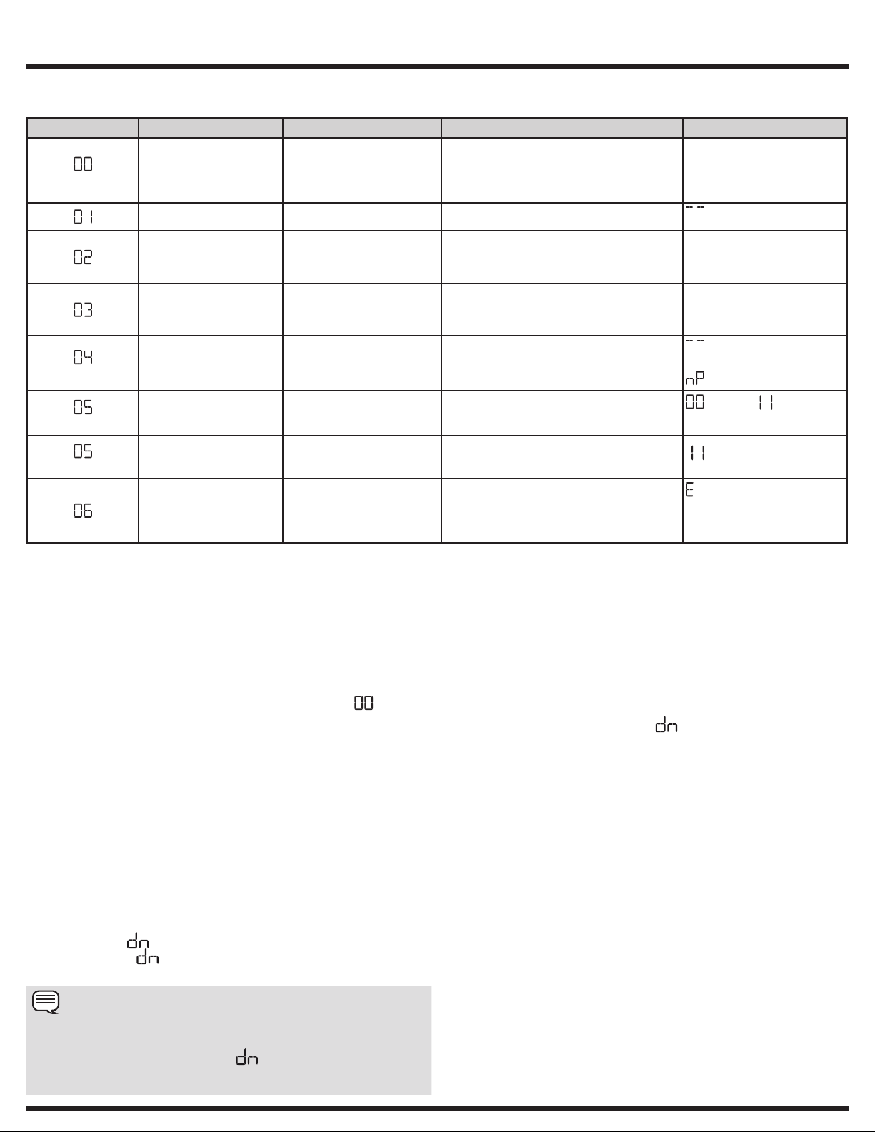
Diagnostic Mode Tests
MODE
NUMBER
pre-test
(select models)
(400 models)
(500 and 600
models)
*The moisture sensor is to the lower left inside the door beside the lint screen. The technician may use metal to short sensor bars. The sensor is touch safe, some materials like dry fingers
or a 10k ohm resistor should have no displayed value.
TEST NAME COMPONENTS UNDER TEST TEST CONDITIONS DISPLAYED FEEDBACK
Lights, Buttons LED indicators
Motor, NO HEAT, HUM ONMotor relay
Motor, NTC1 ctrl heater,
HUM ON, NTC1 temp on
display
Motor, NTC2 ctrl heater,
HUM ON, NTC2 temp on
display
HUM ON, Mist valve ON Mist triac
Moisture sensor circuit
open and short*
Capacitive moisture
sensor circuit check
Error history The last 3 errors in memory Errors are most recent first
LCD screen
Button response
Door switch
Motor relay
Door switch
Heater relay
NTC1
Motor relay
Door switch
Heater relay
NTC2
Valve
Moisture sensor Moisture sensor expects to read "open
Capacitive moisture sensor Moisture sensor valve read by main
Drum rotates for 10 mins
(if door closed)
Drum rotates for 10 mins
(if door closed), heater is on until NTC1
reads 44 C
Drum rotates for 10 mins
(if door closed), heater is on until NTC2
reads 120 C
Mist on for 10 mins
(if door closed)
circuit" condition and "short circuit"
condition*
control board is inside the predefined
threshold
(in order of history)
Note: Pressing temp + select (set)
keys together clears error history
Number of key pressed.
Note: This number may not
necessarily correspond to key
number on table on page 1.
NTC1 reading
NTC2 reading
on units with mist valve;
on units without mist valve
(open) and (short circuit)
with nothing if sensor is between
working correctly
precedes the 2 character alarm
code, alternating through the alarms
Demo Mode:
The Demo works in two ways: Interactive Mode and Automatic Loop.
The Interactive Mode enables the customer to use the interface with-
out activating the appliance. The machine behavior appears similar to
normal operation. Pressing the start button turns on the appliance. The
display will count down by the second from the maximum time displayed
with its respective cycle. The appliance turns off when it reaches “ ”.
The Automatic Loop will engage if no one interacts with the user interface for 3 minutes, or the start button hasn’t been pressed. The machine
will simulate a cycle execution on the display only.
Entering Demo Mode:
1 Press power and look for console light up.
2 For Rotary Dial Cycle Select Dryer: Within 10 seconds select
casual and then simultaneously press and hold temp and select.
buttons for 3 seconds. Skip to Step 4.
3 For Push Button Cycle Select Dryer: Within 10 seconds select
delicates and then simultaneously press and hold temp and select
(set) buttons for 3 seconds. Continue to Step 4.
4 The message “ ” will blink 3 times in the center display.
5 If “ ” message does not appear, turn off machine and repeat
previous steps.
NOTE
Once Demo Mode is activated, every time the machine is turned on,
Demo Mode is automatically recalled; this occurrence is signaled at
the start-up by the text “ ” flashing 3 times in the center display.
Unplugging the unit will not clear Demo Mode. See “Exiting Demo
Mode” for more information.
Exiting Demo Mode:
To exit Demo Mode, perform the same sequence used to enter
Demo Mode.
1 Press cycles to advance the cycle selection to Delicates.
2 Press start; then Press cancel.
3 Press power to turn the unit off.
4 Press power to turn the unit on. The unit will display will flash “ ”
3 times on the numeric display.
5 Press and hold temp and select (set) simultaneously. The appliance
will beep once, the numeric display will cycle off and on. The appliance will then beep with the normal power on sequence.
You may also perform a Factory Default Reset - see below.
Factory Default Reset:
1 Press power and look for console light up.
2 Wait at least 10 seconds, then simultaneously press and hold the
dryness (dry level) and options buttons for 3 seconds. Audible
signal will indicate that the settings have been reset.
Recalling Last Error Code:
1 Press power and look for console light up.
2 Wait at least 10 seconds, then simultaneously press and hold temp
and select (set) buttons for 3 seconds.
3 The display will show the last error in memory.
4 Clear the display and return to normal operation by touching any
button or by pressing the power button.
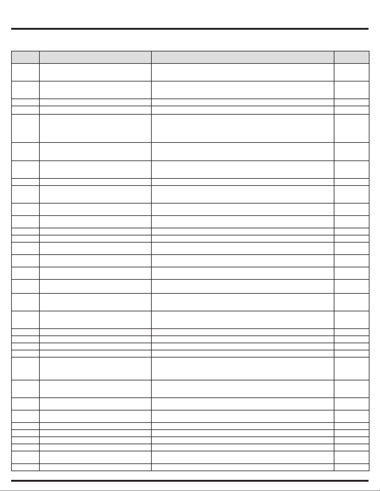
Dryer Error Codes
Dryer Error Codes
3
Error
Code
34 Capacitive sensor values read by main control
35 Capacitive sensor assembly communication
41 Door opened at cycle start Door open Door open
42 Door closed sensing error Door switch or wiring or sensing circuit on main board failure Yes
51 Drum motor relay error With line safe relay closed, motor sensing detects voltage on motor
52 Drum motor start sensing error Motor relay driven but start sensing not congruent
53 Drum motor centrifugal switch error Motor driven but sensing not congruent
54 Drum motor sensing error Drum motor relay sensing circuit failure (main board failure) No
61 Heater relay error 1. Heater disconnected (wiring or connector failure)
63 Heater short error 1. Heater sensing circuit failure (main board failure)
64 Heater open error 1. Heater sensing circuit failure (main board failure)
65 Thermostat open Heater thermostat trip No
67 Heater sensing error Heater sensing circuit failure (main board failure) No
71 NTC1 (OPEN) error 1. NTC open/disconnected
72 NTC1 (SHORTED) error 1. NTC short
73 NTC2 (OPEN) error 1. NTC open/disconnected
74 NTC2 (SHORTED) error 1. NTC short
91 User Interface communication problem with main
92 User Interface mother board protocol mismatch 1. Wiring failure
93 MCF checksum error Wrong machine configuration file in main board Yes
94 CCF checksum error Wrong cycle configuration file in main board Yes
97 Missing program on CTF error Software problem in main board Yes
9C User Interface configuration checksum error Software problem between main board and User Interface board Yes
9E User Interface touch sensor not working One or more touch buttons have calibration problems.
H1/B1 Power supply frequency out of range 1. Power supply problems
H2/B2 Power supply amplitude out of range (too HIGH) 1. Power supply problems - too HIGH VOLTAGE
H3/B3 Power supply amplitude out of range (too LOW) 1. Power supply problems - too LOW VOLTAGE
H4/B4 Line wiring error Wrong line wiring/connection Yes
HA/BD Line safe relay short circuit error Line safe relay problem (main board failure) No
HE/BE Line safe error Line safe relay problem (main board failure) No
HF/BF Line safe sensing error Line safe sensing circuit failure (main board failure) No
F1 Ventilation blocked error Air flow duct clogged or blocked, remove debris and clean and check one
F6 Safety reset error Main board fault No
Error Description Possible Causes Display
board is not within the predefined threshold
(500 and 600 series only)
problem with main control board
(500 and 600 series only)
board
Check wiring between main control board and capacitive sensor assembly
1. If wiring is good, replace capacitive sensor assembly
2. If problem is not corrected, replace main control board
Check wiring between main control board and capacitive sensor assembly
1. If wiring is good, replace capacitive sensor assembly
2. If problem is not corrected, replace main control board
1. Motor short circuit to ground (motor or wiring)
2. Electrical noise
3. Line safe relay problem (main board failure)
4. Motor relay open or short
1. Motor fault
2. Main board fault
1. Motor fault
2. Main board fault
2. Heater failure
3. Heater relay failure (open circuit)
2. Heater failure
2. Heater failure
2. Main board fault
2. Main board fault
2. Main board fault
2. Main board fault
Check wiring between main control board and user interface board
1. If wiring is good, replace user interface board
2. If problem is not corrected, replace main control board
2. User Interface board failure
3. Main board failure
1. Electrical noise
2. Humidity/water on UI board
3. UI board defective
2. Wrong MCF
3. Main board failure
2. Main board failure
2. Main board failure
way vent operation
Notification
Yes
Yes
No
No
No
No
No
No
No
No
No
No
No
No
No
Yes
Yes
Yes
Yes
4
Fiche technique de la sécheuse
Ce manuel est destiné aux techniciens de service qualifiés seulement.
Les éléments de sécurité dans ce manuel sont dotés d'une étiquette
AVERTISSEMENT ou PRUDENCE en fonction du type de risque
décritci-dessous:
TABLE DES MATIÈRES
Fiche technique de la sécheuse ............................................................. 4
Essais en mode diagnostic et mode démo ............................................ 5
Codes d’erreur de la sécheuse .............................................................. 6
Schéma de câblage ............................................................................. 10
MISE EN GARDE
PRUDENCE
PRUDENCE
Sauf indication contraire, coupez le courant avant d'entreprendre
l'entretien.
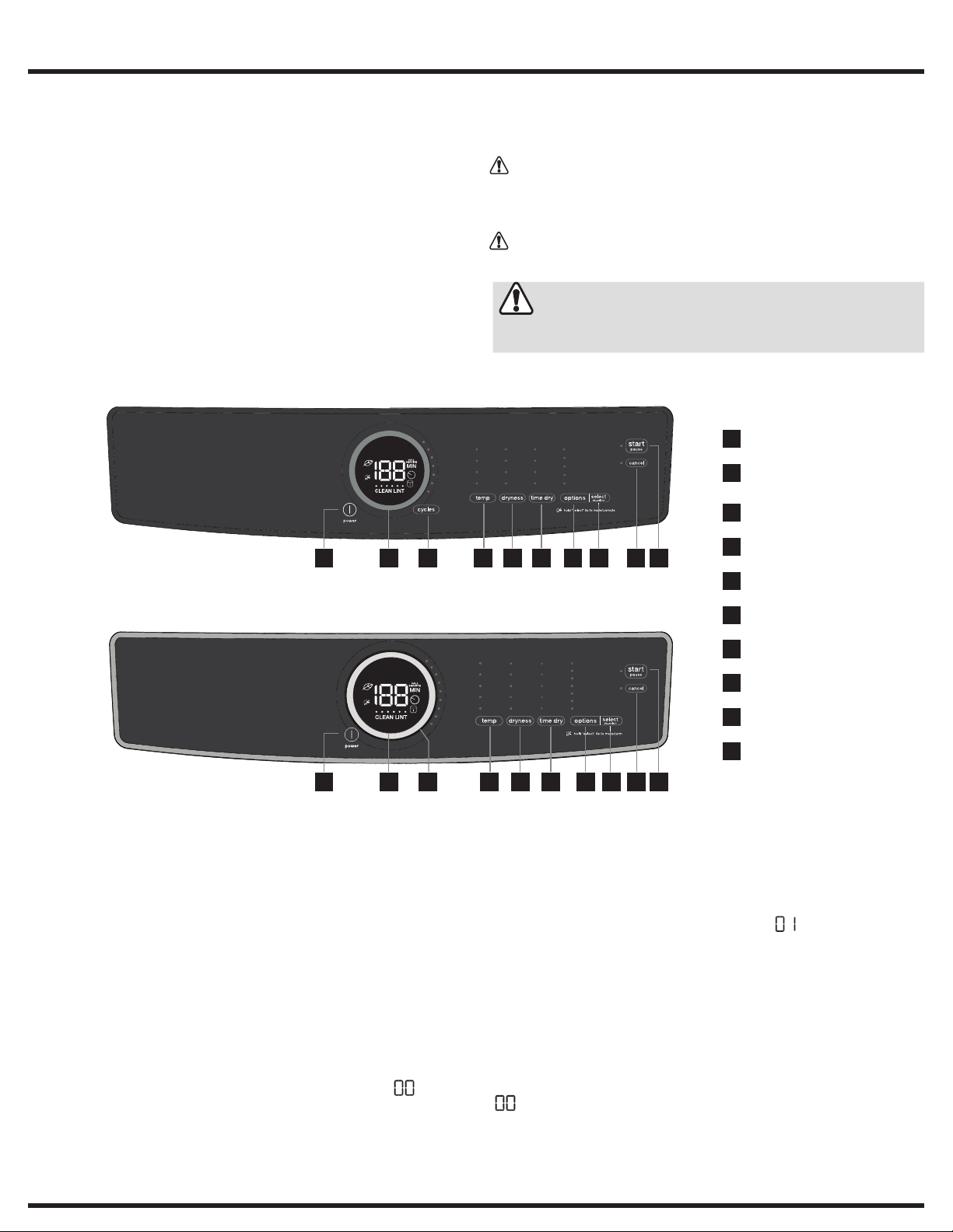
Cycle avec bouton-poussoir, sélectionnez l'interface utilisateur < dryer > (séchage)
2 71 63 854 9
Cycle avec cadran rotatif, sélectionnez l'interface utilisateur < dryer > (séchage)
Ce symbole vous avertit des situations
pouvant causer des dommages
matériels, des lésions corporelles
graves,voire la mort.
Ce symbole vous avertit des situations
susceptibles de causer des lésions
corporelles ou des dommages matériels.
power
1
mise en marche
cycle status display
2
indicateur
d’état du cycle
cycles
3
sélecteur de cycle
temp
4
10
température
dryness (dry level)
5
niveau de séchage
time dry (dry time)
6
durée du séchage
options
7
2 71 63 9854 10
Passage au mode Diagnostic :
1. Appuyez sur la touche < power> et validez que la console s'al-
lume.
2. Tournez la bague de sélection des cycles (certains modèles) ou appuyez plusieurs fois sur la touche < cycle>(sur d'autres modèles)
pour régler le cycle sur normal.
3. Appuyez sur la touche <start>.
4. Éteignez la machine en appuyant sur touche < power>.
5. Éteignez la machine en appuyant sur touche < power>
à nouveau.
6. Dans les 10 secondes, maintenez simultanément les touches
<temp> + < select > enfoncées pendant 3 secondes.
7. Le mode Diagnostic est actif lorsque les DEL clignotent en
séquence. Il s'agit de la position d'essais préliminaires « »
destouches et des voyants.
select (set)
8
sélectionner (régler)
cancel
9
annuler
start / pause
10
démarrer/pause
Défilement des essais en mode Diagnostic:
Les tests sont sélectionnés de la même manière que la sélection des
cycles.
Voir le tableau Essais en mode Diagnostic.
Pour commencer, maintenez la touche < cycles> enfoncée pendant
2secondes. L'unité passe au premier essai et « » clignote à l'écran.
Appuyez sur la touche < cycles> pour passer au prochain essai.
Appuyez sur la touche < temp> pour revenir à l'essai précédent. Les
numéros de séquence des essais s'affichent brièvement lorsque chacun
est sélectionné. Les numéros d'essai affichés correspondent également
aux voyants de sélection à droite de l'affichage numérique; en commençant par la DEL supérieure, en descendant.
Quitter le mode Diagnostic:
Maintenez la touche < power> enfoncée pendant 3 secondes tandis
que le témoin ou la touche d’essai est désactivée
« », ou débranchez l’appareil.
Aux É.-U.: 1-877-435-3287
www.electroluxappliances.com
A11199902 (1803)
Au Canada: 1-800-265-8352
Essais en mode diagnostic et mode démo
Essais en mode Diagnostic
MODE NUMÉRO LIBELLÉ DE L'ESSAI COMPOSANTS SOUS ESSAI CONDITIONS D’ESSAI RÉTROACTION AFFICHÉE
Lampes et témoins
lumineux, boutons
essai préliminaire
Moteur, AUCUNE
CHALEUR, HUM. ACTIVÉ
Moteur, chauffage ctrl.
NTC1, HUM. ACTIVÉE,
température NTC1 affichée
Moteur, chauffage ctrl.
NTC2, HUM. ACTIVÉE,
température NTC2 affichée
HUM. ACTIVÉE, vanne
debrumisation ACTIVÉE
(certains modèles)
Circuit du capteur d'humidité
(modèles 400)
(modèles 500 et600)
*Le capteur d'humidité est situé en bas à gauche à l'intérieur de la porte près de la crépine à charpie. Le technicien peut utiliser du métal pour court-circuiter les barres de détection.
Lecapteur est protégé contre le contact des doigts; certains matériaux comme des doigts secs ou une résistance de 10kΩ ne doivent pas afficher de valeur.
ouvert et court-circuit*
Vérification de circuit du
capteur d'humidité capacitif
Historique des erreurs Les 3 dernières erreurs
Témoins DEL
Panneau ACL
Réponse des boutons
Relais de moteur
Commutateur de la porte
Relais de moteur
Commutateur de la porte
Relais d’élément chauffant
NTC1
Relais de moteur
Commutateur de la porte
Relais d’élément chauffant
NTC2
Triac de brumisation
Vanne
Capteur d'humidité Le capteur d'humidité s'attend à lire les états
Détecteur d'humidité capacitif. La lecture de la vanne du capteur d'humidité
sauvegardées en mémoire
Le tambour tourne pendant 10minutes
(silaporte est fermée)
Le tambour tourne pendant 10minutes (si la
porte est fermée), lechauffage est en marche
jusqu'à ceque NTC1 indique 44°C
Le tambour tourne pendant 10minutes (si la
porte est fermée), lechauffage est en marche
jusqu'à ceque NTC2 indique 120°C
Brumisation pendant 10 minutes (silaporte est
fermée)
«circuit ouvert» et «court-circuit» *
par le tableau de commande principal est
àl'intérieur du seuil prédéfini
Les erreurs les plus récentes en premier
(parordre historique)
Remarque: Appuyer sur les touches
<temp> +<select> simultanément efface
l'historique des erreurs
Numéro de la touche enfoncée.
Remarque: Ce numéro
peut ne pas correspondre
nécessairement au numéro de
touche du tableau dela page 1.
Lecture NTC1
Lecture NTC2
sur les appareils avec
vanne debrumisation;
sur les électroménagers
avec vanne de brumisation;
(ouvert) et (court-circuit)
ou rien si le capteur est entre
les deux
et fonctionne correctement
précède le code d'alarme à
2 caractères, alternant entre les
alarmes
5
Mode Démo:
Le mode Démo (démonstration) fonctionne de deux façons: en mode
interactif et en boucle automatique.
Le Mode interactif permet au client d'utiliser l'interface sans activer l'élec-
troménager. Le comportement de la machine semble normal. Appuyer sur le
bouton de démarrage met l'électroménager en marche. L'affichage compte
à rebours seconde par seconde à partir de la durée maximale affichée selon
son cycle respectif. L'électroménager s'éteint lorsqu'il atteint« ».
Le mode de boucle automatique s'active si personne n'interagit avec
l'interface utilisateur pendant 3 minutes ou si le bouton de
démarrage n'apas été enfoncé. La machine simule l'exécution d'un
cycle uniquement à l'écran.
Pour lancer le mode Demo:
1 Appuyez sur la touche < power> et validez quelaconsole s'al-
lume.
2 Avec le cadran rotatif, sélectionnez le cycle < dryer> (séchage):
Dans les 10 secondes, sélectionnez < casual> puis appuyez simultanément et maintenez les touches < temp> et <select>. enfoncées
pendant 3 secondes. Passer à l'étape 4.
3 Avec le bouton-poussoir, sélectionnez le cycle < dryer>
( séchage): Dans les 10 secondes, sélectionnez < delicates>
puis appuyez simultanément et maintenez les touches <temp>
et <select> enfoncées pendant 3 secondes. Passez à l'étape 4.
4 Le message « » clignote 3 fois dans l'écran central.
5 Si le message « » n'y apparaît pas, éteignez la machine
et répétezles étapes précédentes.
REMARQUE
Une fois le mode Démo activé, chaque fois que la machine est allumée,
le mode Démo est rappelé automatiquement; cette occurrence est
signalée au démarrage par les lettres « » clignotant 3 fois à l'écran
central. Débrancher l'appareil n'efface pas le mode Démo. Pour plus
d'informations, voir «Quitter le mode démo».
Quitter le mode Démo:
Pour quitter le mode Démo, effectuez la même séquence utilisée
pour accéder le mode Démo.
1 Appuyez sur la touche < cycles> pour faire avancer la sélection
du cycle vers Délicats.
2 Appuyez sur < start>; appuyez ensuite sur < cancel> .
3 Appuyez sur touche < power> pour éteindre l'électroménager.
4 Appuyez sur< power> pour allumer l'électro ménager. L'affichage
numérique de l'appareil clignote « » 3 fois.
5 Appuyez et maintenez les touches < temp> et < select> en-
foncées simultanément. L'électroménager émet unbip, l'affichage
numérique s'allume et s'éteint. L'appareil émet alors un bip avec la
séquence de mise en marche normale.
Vous pouvez également effectuer une réinitialisation aux paramètres
pardéfaut de l'usine. Voir ci-dessous.
Réinitialisation aux paramètres par défaut de l'usine :
1 Appuyez sur la touche < power> et validez que laconsole
s'allume.
2 Attendez au moins 10 secondes, puis appuyez simultanément sur
les touches < dryness> et < options> enfoncées pendant 3 secondes. Le signal sonore indique que les réglages ont été réinitialisés.
Rappel du dernier code d'erreur:
1 Appuyez sur la touche < power> et validez quelaconsole
s'allume.
2 Attendez au moins 10 secondes, puis appuyez simultanément
surles touches < temp> et <select> enfoncées pendant 3
secondes.
3 L'écran affiche le dernier code d'erreur en mémoire.
4 Effacez l'affichage et revenez à un fonctionnement normal
en appuyant sur n'importe quel bouton ou en appuyant sur
la touche<power>.
 Loading...