

Electrolux EI30EW38TS User Manual
IMPORTANT
DO NOT REMOVE THIS BAG
OR DESTROY THE CONTENTS
WIRING DIAGRAMS AND SERVICE
INFORMATION ENCLOSED
REPLACE CONTENTS IN BAG
ELECTRIC WALL OVENS WITH MODULAR OVEN CONTROLS
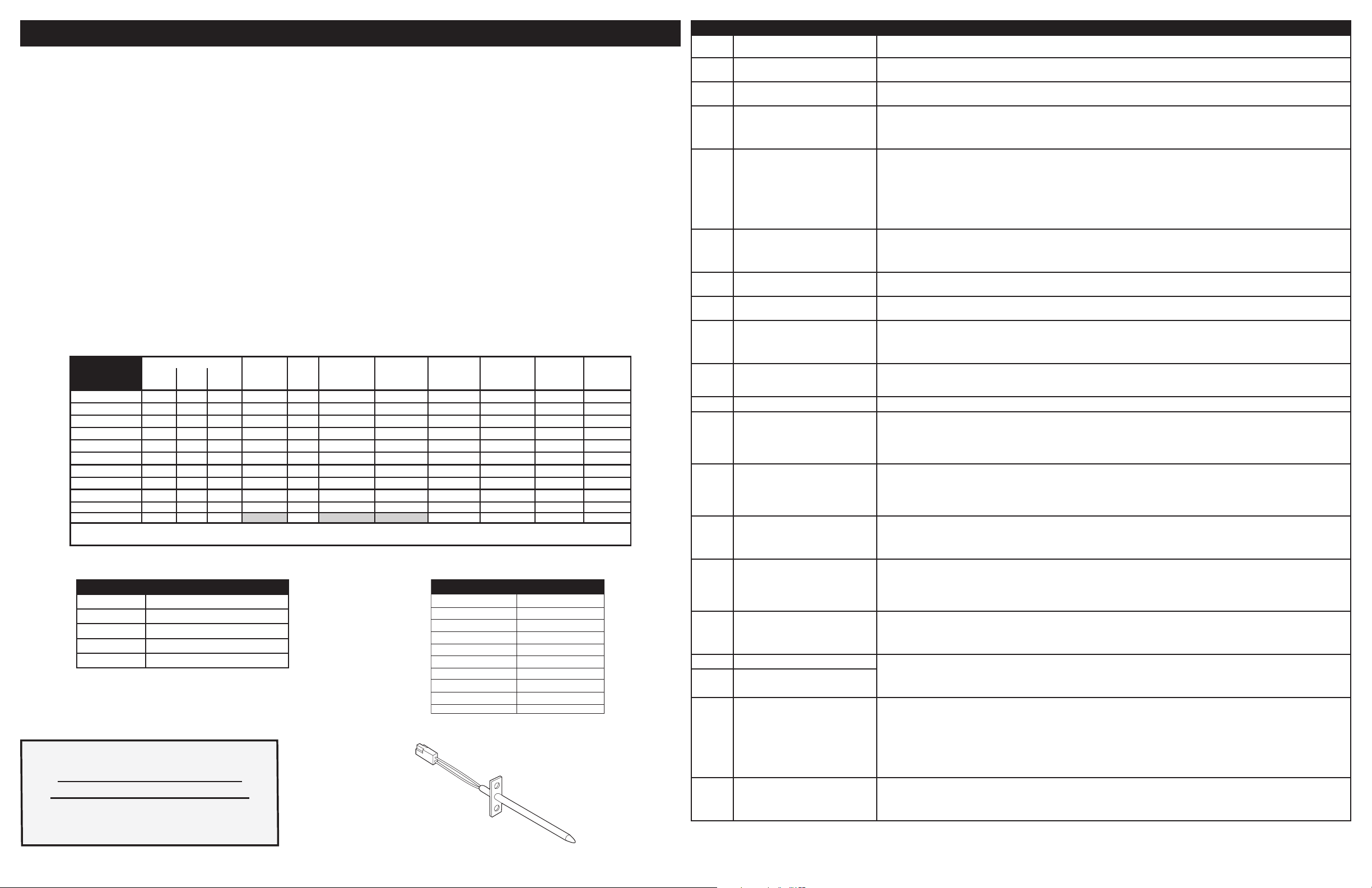
Resistance Temperature Detector
NOTICE: This service data sheet is intended for use by persons having electrical and mechanical training and a level of knowledge of these subjects generally considered acceptable
in the appliance repair trade. The manufacturer cannot be responsible, nor assume any
liability, for injury or damage of any kind arising from the use of this data sheet.
IMPORTANT NOTE: This unit includes an EOC (electronic oven control). This board is not
eld-repairable. Verify the unit has the proper oven relay board, oven user interface board,
and touch panel based on the model number and parts catalog.
Safe Servicing Practices
To avoid the possibility of personal injury and/or property damage, it is important that safe servicing practices be observed. The following are some, but not all, examples of safe practices.
1. Do not attempt a product repair if you have any doubts as to your ability to complete it
in a safe and satisfactory manner.
2. Before servicing or moving an appliance, remove power cord from electric outlet, trip
circuit breaker to Off, or remove fuse.
3. Never interfere with the proper installation of any safety device.
4. Use only replacement parts specied for this appliance. Substitutions may not comply
with safety standards set for home appliances.
5. Grounding: The standard color coding for safety ground wires is green or green with
yellow stripes. Ground leads are not to be used as current carrying conductors. It is
extremely important that the service technician reestablish all safety grounds prior to
completion of service. Failure to do so will create a potential hazard.
CIRCUIT
ANALYSIS
MATRIX
Bake X X X X X X X X
Broil X X X X
Conv. Bake X X X X X X X X
Conv. Roast X X X X X X X X
Air Sous Vide X X X X X X
Clean X X X X X
Locking X
Unlocking X
Light X
Door Open X
Door Closed X
Elements
BakeP7BroilK2Conv.
P8
Door
Motor
J20-10
Light
J20-6
Conv. Fan
Low Speed
J20-9, J19-6
NOTES: Bake, broil, and convection elements alternate cycles. Convection fans may run during preheat and may run intermittently during
non-convection functions to improve cooking performance.
MEAT PROBE TEMPERATURE VS RESISTANCE TABLE
Temperature Probe Resistance
77 °F / 25°C 50.020 Kohm +/- 6%
122 °F / 50°C 18.020 Kohm +/- 5%
176 °F / 80°C 6.290 Kohm +/- 5%
212 °F / 100°C 3.400 Kohm +/- 5%
SERVICE DATA SHEET
p/n A00980644 Rev A (2017/05)
6. Prior to returning the product to service, ensure that:
• All electric connections are correct and secure.
• All electrical leads are properly dressed and secured away from sharp edges,
high-temperature components, and moving parts.
• All uninsulated electrical terminals, connectors, heaters, etc. are adequately
spaced away from all metal parts and panels.
• All safety grounds (both internal and external) are correctly and securely reassembled.
• All panels are properly and securely reassembled.
Temperature Adjustment
Refer to the Use & Care Manual for directions on how to adjust the oven temperatures.
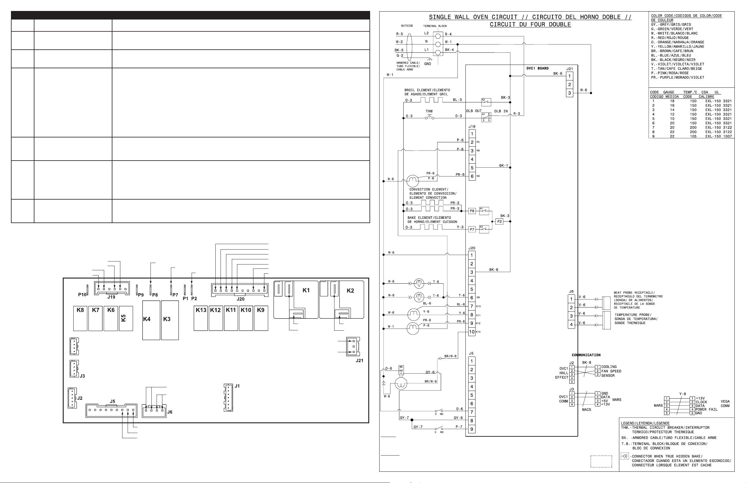
Modular Control Systems
This appliance is equipped with a modular system of controls. The modular system consists
of various boards which communicate with one another to drive cooking functions. Oven
functions, if available, operate through an oven user interface (UI or UIB) and an oven relay
board. Cooktop functions, if available, operate through a cooktop UI/UIB and a cooktop
relay board. There may be additional boards which work within the system to drive specic
functions (refer to the schematics and diagrams and this sheet). Low voltage operating and
communications power for the modular boards is provided through the wiring schemes.
The boards that generate low voltage operating and communications power depend upon
the individual control system (refer to the schematics and diagrams on this sheet). These
voltages are only the operational voltages. Do not use these voltages as conrmation of
communication between the boards. Communication occurs through software programming
on each board. This communication is not detectable by volt ohmmeters. The programming
is self-monitored and the UI displays will show error codes based on detected failures. The
individual boards are not eld repairable. See the schematics and diagrams included on this
sheet for more unit-specic details.
Conv. Fan
High Speed
J19-2, J19-3
Cooling Fan
Low Speed
J20-7
Temperature °F (°C)
32 ± 1.9 (0 ± 1.0)
75 ± 2.5 (24 ± 1.3)
250 ± 4.4 (121 ± 2.4)
350 ± 5.4 (177 ± 3.0)
450 ± 6.9 (232 ± 3.8)
550 ± 8.2 (288 ± 4.5)
650 ± 9.6 (343 ± 5.3)
900 ± 13.6 (482 ±7.5)
Probe circuit to case ground
Cooling Fan
High Speed
J20-8
RTD SCALE
Door
Switch
J5-9
Resistance (ohms)
1000 ± 4.0
1091 ± 5.3
1453 ± 8.9
1654 ± 10.8
1852 ± 13.5
2047 ± 15.8
2237 ± 18.5
2697 ± 24.4
Open circuit/infinite resistance
DLB L2 out
K1
ELECTRONIC OVEN CONTROL (EOC) FAULT CODE DESCRIPTIONS
Fault
Code
F01 F02
F04 F05
F03 The oven user interface board is
F10 Oven temperature runaway: the cavity
F11 Stuck key: a key has been detected
F12 Keyboard conguration alarm: the
F13 Data written to non-volatile memory
F15 Keyboard error Disconnect power, wait 30 seconds and reapply power. If fault returns upon power-up replace the control assembly (UIB and touch
F16 The oven user interface board cannot
F17 The oven user interface board is un-
F18 Oven relay board failure (wiggler) Replace the oven relay board.
F19 The oven user interface board is un-
F22 Communication failure between the
F23 Communication failure between the
F25
F27
F28
F29
F30 Open oven temperature sensor (RTD) 1. Check probe circuit wiring for possible open or short condition.
F31 Shorted oven temperature probe
F33 Meat probe temperature sensor short-
F45 Cooling fan speed too low 1. Check if the cooling fan blades are blocked.
Description of Error Code Suggested Corrective Action
Touch panel failure Disconnect power, wait 30 seconds and reapply power. If fault returns upon power-up replace the control assembly (UIB and touch
incorrectly congured.
temperature has been detected in
excess of the maximum safe operating
temperature.
has pressed continuously for 30 seconds or more.
oven user interface board received
from the touch panel a key code that
does not match the key map.
has failed verication
read the potentiometers.
able to congure the touch panel.
able to congure the oven relay board
oven user interface board and the
oven relay board
oven user interface board and the
glass touch panel
The communication between the over
user interface and the oven relay
board cannot be initiated.
The communication between the oven
user interface and the touch panel
cannot be initiated.
(RTD)
ed or too hot
panel).
Replace the control assembly (UIB and touch panel). Make sure you install the latest revision available for this model.
1. If oven is overheating, disconnect power. Check oven temperature probe (RTD) and replace if necessary.
2. If the oven temperature probe is good and if oven continues to overheat when power is reapplied, replace the oven relay board.
1. If a key was pressed inadvertently for a long time this error code will be displayed. Make sure there is nothing (water, utensils)
in contact with the keyboard. The fault code should go away once the key is released and the Stop key is pressed. If the F011
error comes back when a key is pressed it means the error condition is still there. If the F011 error does not come back it means
the error condition is gone and the oven can be used.
2. If the fault code cannot be cleared, test the wiring harness between oven user interface board (connector I2C1 or I2C2) and
touch panel (connector I2C1 or I2C2).
3. If the fault code cannot be cleared and the wiring is good, the touch panel is most likely defective: replace the control assembly
(UIB and touch panel).
Disconnect power, wait 30 seconds and reapply power. If fault returns upon power-up replace the control assembly (UIB and touch
panel).
Disconnect power, wait 30 seconds and reapply power. If fault returns upon power-up replace the control assembly (UIB and touch
panel).
panel).
1. Verify that potentiometers are in OFF position correctly, disconnect power to the unit, wait 30 seconds, then reapply power.
2. If fault returns, verify harness going to the POTS connector of the user interface board to both potentiometer components.
3. If fault persists, replace potentiometers.
4. If fault persists, replace the control assembly (UIB and touch panel)
1. Disconnect power to the unit, wait 30 seconds, then reapply power.
2. If fault returns, verify harness going to I2C1 or I2C2 connector of the touch panel.
3. If fault persists, replace the control assembly (UIB and touch panel)
1. Disconnect power to the unit, wait 30 seconds, then reapply power.
2. If fault returns, verify connection between the oven user interface board (MACS1 or MACS2 connector) and the oven relay
board (connector J3 or J4).
3. If fault persists, replace the control assembly (UIB and touch panel)
4. If fault persists, replace the relay board.
1. Disconnect power, wait 30 seconds and reapply power. Check if error condition is still there.
2. Test wiring harness between oven user interface board (connector MACS1 or MACS2) and oven relay board (connector J3 or
J4).
3. If wiring harness is good replace oven relay board.
4. If the problem persists replace the control assembly (UIB and touch panel).
1. Disconnect power, wait 30 seconds and reapply power. Check if error condition is still there.
2. Test wiring harness between oven user interface board (connector I2C1 or I2C2) and touch panel (connector I2C1 or I2C2).
3. If wiring harness is good replace touch panel.
4. If the problem persists replace the control assembly (UIB and touch panel).
1. Disconnect power to the unit, wait 30 seconds, then reapply power.
2. If fault returns, verify connection between the oven user interface board (MACS1 or MACS2 connector) and the oven relay
board (connector J3 or J4).
3. If fault persists, replace relay board.
4. If fault persists, replace the control assembly (UIB and touch panel).
1. Disconnect power to the unit, wait 30 seconds, then reapply power.
2. If fault returns, verify touch panel is connected (verify harness going to I2C1 or I2C2 connector) and is getting power from the
oven user interface.
3. If fault persists, replace the control assembly (UIB and touch panel).
2. Verify RTD resistance at room temperature (compare to probe resistance chart). If resistance does not match the chart, replace
the RTD probe.
3. If the problem persists replace the oven relay board.
1. The error is triggered if the meat probe sees a temperature in excess of 392°F. Make sure the meat probe was not used in such
way that it could have seen such temperature. If the tip of the probe is not inserted in the meat it will see the cavity temperature,
which can be higher than 392°F (depending on the setpoint) and trigger the alarm.
2. When the meat probe is connected to the socket inside the oven cavity, if the meat probe is not fully inserted into the socket it
may short the contacts and cause the error. Make sure the probe is inserted as much as it can.
3. Verify meat probe resistance at room temperature. Compare to meat probe resistance chart. If the meat probe does not match
the chart, replace it.
4. If the above steps failed to correct the problem, replace the oven relay board.
2. Conrm tachometer harness is connected on fan and on oven control.
3. Replace cooling fan.
4. Replace oven control.
LATCH MOTOR
LATCH MOTOR SWITCH
J2
ELECTRONIC OVEN CONTROL (EOC) FAULT CODE DESCRIPTIONS
Fault
Code
Description of Error Code Suggested Corrective Action
F46 Cooling fan speed too high 1. Check for mechanical obstruction in the air path.
2. Replace cooling fan.
3. Replace oven control.
F50 A/D Out of Range: the oven relay
board is unable to read the status of
the switches (door, MDL)
F90 Motor Door Lock mechanism failure.
The oven control does not see the
Motor Door Lock running.
1. Check to ensure that the connections between the door switch, MDL and temp probes are properly connected. This includes all
splices and junctions.
2. If the above step failed to correct the problem, replace the oven relay board.
1. Disconnect power to the unit, wait 30 seconds, then reapply power. Try again to make the door lock or unlock (ex: initiate a
Lockout or a Clean cycle).
2. Check if the Lock Motor is running or not. If it is not running, test the wiring between the Lock Motor and the oven relay board.
If the wiring is good, check if there is 120VAC at the motor when it is expected to run to see if the failure originates from a bad
motor (120VAC present but not turning) or a problem with the relay board (J20 pin 10 on the oven relay board is the output to
the Lock Motor). The Lock Motor can also be tested by applying 120VAC directly to the motor (unplug it from the relay board
rst). If the Lock Motor does not run when 120VAC is applied replace the Lock Motor Assembly. If it is the relay board that does
not provide 120VAC to the Lock Motor replace the oven relay board.
3. If the Lock Motor is running but the oven control cannot nd the locked or unlocked position (ex: motor turns continuously until
F90 fault code is generated) the Lock Switch needs to be veried. Check wiring between Lock Switch and oven relay board.
Verify with ohmmeter if the switch makes contact properly (verify continuity with ohmmeter when the switch is pressed). If the
Lock Switch is defective replace the Motor Lock Assembly.
4. If all above steps failed to correct the situation, replace the oven relay board.
F95 Motor Door Lock mechanism failure.
The Motor Door Lock does not stop
running or the Lock Switch sends an
1. The problem can be caused by a faulty Lock Switch or by a defective oven relay board. If the Motor Door Lock is always running (as if the relay controlling it is stuck closed) replace the oven relay board.
2. If the motor is not always running replace the Motor Lock Assembly.
invalid signal.
F96 The oven door has been detected
open during a Self Clean cycle.
1. This error occurs if the door switch has lost its contact during a Self Clean cycle. Make sure the oven door closes well and fully
presses on the door switch plunger when the door is locked, and no one attempted to pull on the oven door during the Self
Clean cycle.
2. Test continuity of wiring between the door switch and the oven relay board, make sure the door switch is well connected. With
an ohmmeter, verify the switch is closed when the plunger is pressed. If the door switch is found to be defective replace the door
switch.
3. If the switch and wiring are good and the problem persists, replace the oven relay board.
F97 MDL invalid state. Relay board (OVC)
sensed the motor door lock in a state it
should not be in according to the user
1. Disconnect power to the unit, wait 30 seconds, then reapply power.
2. If fault persists, replace motor door lock.
3. If fault persists, replace the oven relay board.
interface board.
CONV FAN 1
VENT DE CONV 1
HIGH SPEED HAUTE VITESSE
CONV FAN 2
VENT DE CONV 2
HAUTE VITESSE
LOW SPEED
HIGH SPEED
BASSE VITESSE
COMM TO COOLING
FAN SPEED SENSOR
CONVECTION 2 FAN HIGH
CONVECTION 1 FAN HIGH
CONVECTION 2 FAN LOW
1
J4
1
1
L1
1 1
J3 TO USER INTERFACE BOARD
MARS BOARD
VOLTAGES:
1. DC GRD
2. MACS DATA
3. +5V DC
4. +13V DC
1
1
DOOR SWITCH
COMMON
CONVECTION ELEMENT
BAKE ELEMENT
L1
CONV ELEMENT
BAKE ELEMENT
MEAT PROBE
TEMPERATURE PROBE
PROGRAMMING HEADER
1
CONVECTION FAN 1 LOW
COOLING FAN HIGH SPEED
COOLING FAN LOW SPEED
OVEN LIGHT
L1
NEUTRAL
DLB BROIL
L2 OUT/THERM
L2 IN
NEUTRAL
L1
COM L1
BROIL
ELEMENT
1
HALOGEN OVEN LAMP
LAMPE DU FOUR - HALOGENE
HALOGEN OVEN LAMP
LAMPE DU FOUR - HALOGENE
COOLING FAN
VENT DE REFROID
CONV FAN 1
VENT DE CONV 1
LATCH MOTOR
MOTEUR VERROU
MDL - MOTOR DOOR LATCH SWITCH
INTER. DU LOQUET MOTORISÉ DE LA PORTE
CAUTION:
DISCONNECT POWER BEFORE SERVICING UNIT.
LABEL ALL WIRES PRIOR TO DISCONNECTION WHEN SERVICING CONTROLS.
WIRING ERRORS CAN CAUSE IMPROPER AND DANGEROUS OPERATION.
VERIFY PROPER OPERATION AFTER SERVICING.
ATTENTION:
DÉBRANCHEZ L'APPAREIL AVANT DE PROCÉDER À LA RÉPARATION.
IDENTIFIEZ TOUS LES FILS AVANT DE LES DÉBRANCHER LORSQUE VOUS PROCÉDEZ À UNE RÉPARATION.
UNE ERREUR DE FILAGE PEUT CAUSER UN FONCTIONNEMENT INADÉQUAT ET/OU UNE SITUATION DANGEREUSE.
VÉRIFIEZ QUE L'APPAREIL FONCTIONNE CORRECTEMENT APRÈS LA RÉPARATION.
LOW SPEED
BASSE VITESSE
HIGH SPEED
HAUTE VITESSE
LOW SPEED BASSE VITESSE
HIGH SPEED HAUTE VITESSE
INTERRUPTEUR DE PORTE
DOOR SWITCH
OPTIONAL
OPTIONNEL
 Loading...