

Electrolux EHG 9320, EGG 9430, EGG 9420, EHG 9330, EHG 9340 Service Manual
SERVICE MANUAL

1
C O N T E N T S
1. GENERAL NOTES 2
2. HOW DOES GAS BURNER OPERATE 3
3. COMPONENTS SPECIFICATION 4
4. TOOLS 6
5. REPAIR PROCESS 6
5.1 Remove the dirty oil from nozzle
5.2 Remove the gas valve
6. WIRING DIAGRAM 8
7. CONVERSION DETAILS 9
8. SPARE PARTS 10
9. TROUBLE SHOOTING 17

2
1. GENERAL NOTES
1. WARNING: For models which connect to mains electrical power, before exposing any of the
internal electrical wiring the appliance must be disconnected from electrical power by unplugging
the service cord from the electrical outlet. For models which connect to battery power, before
exposing any of the internal electrical wiring the appliance must be remove the battery also.
2. Any servicing carried out on gas containing components where seals are broken including
manifold, regulator, valves and burner supply pipes should be followed by a leak test. Gross leaks
can be detected by connecting a manometer to the regulator test point, pressurising the manifold
and then shutting off the gas with a ball valve. A falling manometer reading indicates a leak.
Small leaks can be located with soap and water applied at the connection.
3. Burner supply pipes leading from the burner control to the burner should have their compression
fittings tightened firmly
but not over tightened
(If a torque spanner is used set this to 10 –
12Nm). If the tubes are damaged they should be replaced. The soundness of the connections on
the burner supply tubes can be tested by blocking the injector orifice temporarily, eg by fitting an
injector that has been blocked and leak testing the fittings.
4. When reassembling the appliance any earth leads which have been disconnected must be re-
connected.
5. Reassembly procedures are a reversal of removal procedures.
6. Replace the spare part with original spare parts. The modify part must not be used.
7.
All the screws in this appliance have been designed for difference purpose. They must be use in
the right position and must be the right dimension. If there are any differences from the original
design they may have the serious excident.
3
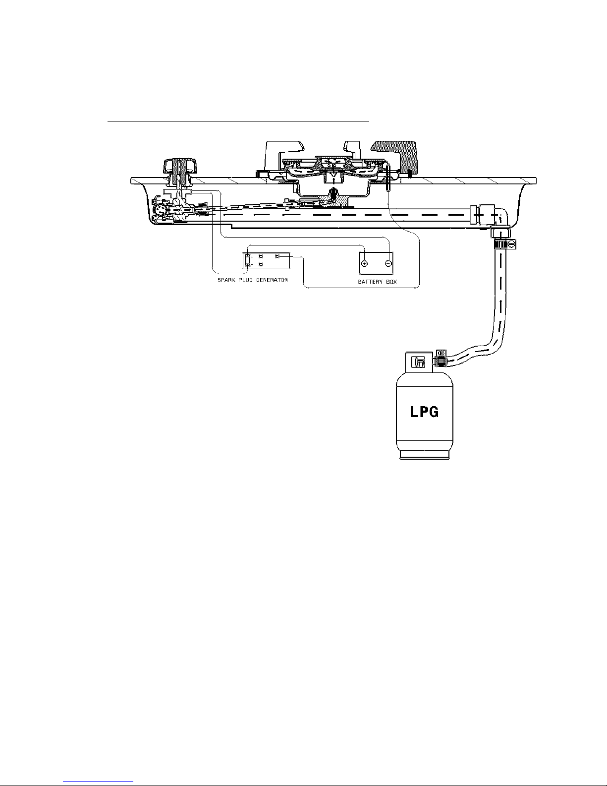
2. HOW DOES GAS BURNER OPERATE
1. Gas tank
2. Low pressure regulator (
Safety warning: Do not
use high pressure regulator)
3. Flexible rubber hose or copper tube
4. Elbow coupling gas with fiber washer (Warning: Do not use regular rubber washer)
5. 2 steps safety valve
6. Burner
7. Ignition switch
8. Battery 1..5V size D
9. Spark generator
4
10. Spark plug
Gas from the tank (1) is released from the low pressure regulator (2) into the hose or tube (3),
travelling pass the elbow coupling to the valve (4). To ignite the burner, press down and turn the
safety valve (5) counter-clockwise simultaneously. This opens up the valve, letting the gas to the
nozzle of the burner (6), and turns the ignition switch to
on (7)
at the same time. The electrical
current is automatically supplied from the battery to spark plug generator (8), and then to the pin
heads (9), causing the ignition (10). The burner is ignited and bursts into flame (11).
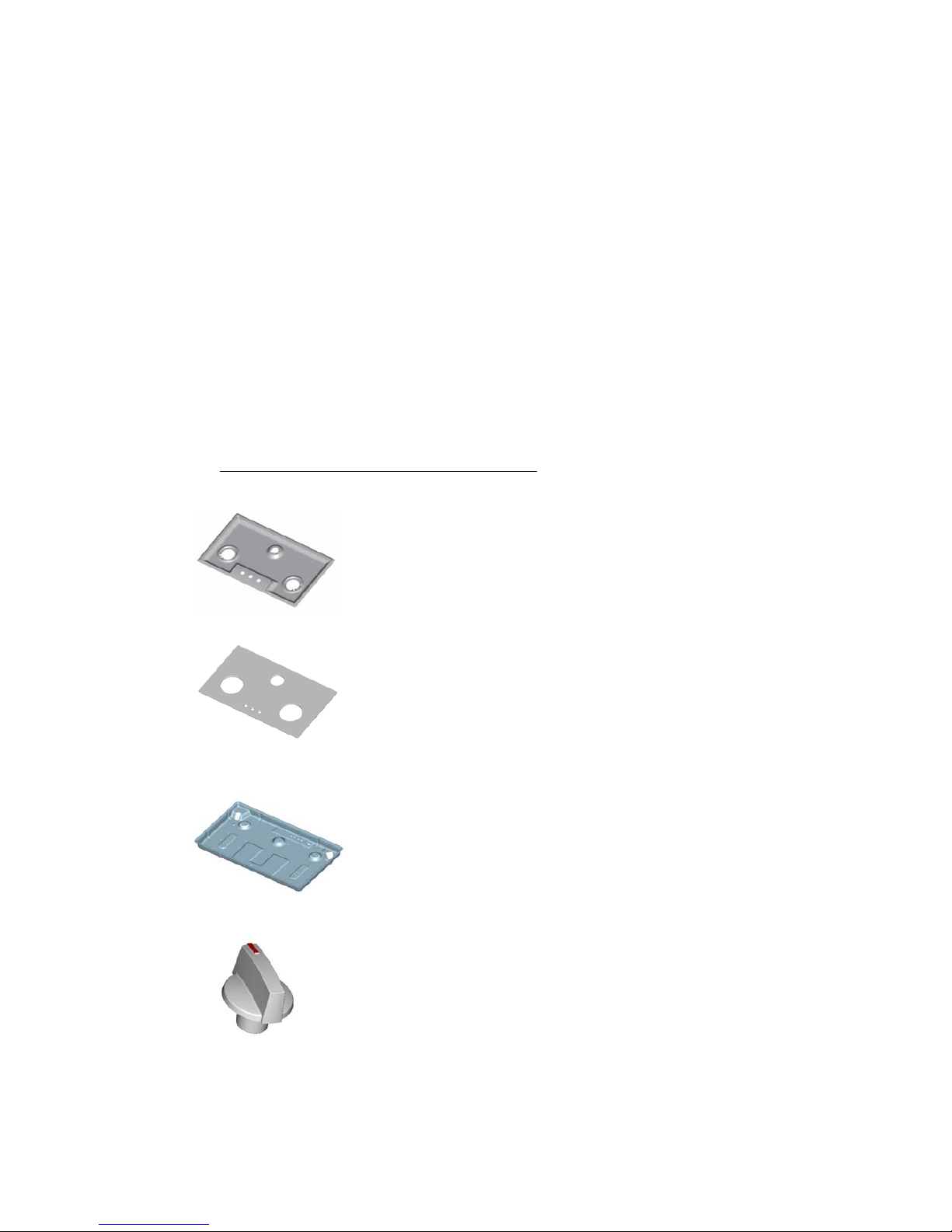
2. COMPONENTS SPECIFICATION
- Stainless top plate
- Glass 3B = Float glass 8.0x500x860 mm
- Bottom plate forming=Zinc coat
- Knob= heat + flame resistance >17

5
- Washer= fiber
- Elbow = Brass (size1/2”)
- Hose end=Brass (size1/2”)
- Rubber grommet (glass model)= Silicone heat resistance
- Rubber grommet (Stainless model)
- Spark generator 4p=1.5Vdc+90C+electrode10KV
- Push button switch 3p=0.1A+250V+130C
- Screw, M4x0.7x10 IP
- Screw, M4x0.7x18 H
- Screw, M3x12T + B stainless
- Screw, #6/32 x 9 PPZF
- Screw, #8 x ½ T+ Z
 Loading...