

Electrolux EFLS527UIW1, EFLS527UTT1, EFLS627UIW1, EFLS627UTT1, EFLW317TIW2 Installation Guide
...
EN FRONT LOAD WASHER
FR LAVEUSE Á CHARGEMENT FRONTAL
ES LAVADORA DE CARGA FRONTAL
INSTALLATION INSTRUCTIONS
INSTRUCTIONS D’INSTALLATION
INSTRUCCIONES DE INSTALACIÓN
A11200201 January 2018

2
Important Safety Instructions
WARNING
For your safety the information in this manual must be followed to minimize the risk of
fire or explosion or to prevent property damage, personal injury or loss of life. Do not
store or use gasoline or other flammable vapors and liquids in the vicinity of this or any
other appliance.
Safety Precautions
Do not attempt to install or operate
your unit until you have read the safety
precautions in this manual. Safety items
throughout this manual are labeled with a
Danger, Warning, or Caution based on the
risk type.
Definitions
This is the safety alert symbol. It is
used to alert you to potential personal injury
hazards. Obey all safety messages that
follow this symbol to avoid possible injury
or death.
DANGER
DANGER indicates an imminently hazardous situation which, if not avoided,
will result in death or serious injury.
WARNING
WARNING indicates a potentially hazardous situation which, if not avoided, could
result in death or serious injury.
CAUTION
CAUTION indicates a potentially hazardous situation which, if not avoided, may
result in minor or moderate injury.
Table of Contents
Important Safety Instructions ................ 2
Installation Requirements ...................... 4
Unpacking Washer ...............................8
Installation Instructions .......................10
Reversing Door ................................... 12
Options ..............................................15
IMPORTANT
Indicates installation, operation, or maintenance information which is important
but not hazard-related.
©2017 Electrolux Major Appliances All rights reserved.

Important Safety Instructions
WARNING
RISK OF FIRE
Read all the following instructions before installing and using this appliance.
• Dispose of the carton and plastic bags after the washer is unpacked. Children
might use them for play. Cartons covered with rugs, bedspreads, or plastic sheets
can become airtight chambers causing suffocation. Place all materials in a garbage
container or make these materials inaccessible to children.
• For your safety the information in this manual must be followed to minimize the risk
of fire or explosion or to prevent property damage, personal injury or loss of life. Do
not store or use gasoline or other flammable vapors and liquids in the vicinity of this
or any other appliance.
• Install the washer according to the manufacturer’s instructions and local codes.
• The electrical service to the washer must conform with local codes and ordinances
and the latest edition of the National Electrical Code, ANSI/NFPA 70, or in Canada,
the Canadian Electrical Code CSA C22.1 part 1.
• To avoid back or other injury, have more than one person move or lift the washer.
• Do not stack a dryer on top of washer already installed on pedestal. Do not stack
washer on top of dryer. Do not stack washer on top of another washer.
• The instructions in this manual and all other literature included with this washer are
not meant to cover every possible condition and situation that may occur. Good safe
practice and caution MUST be applied when installing, operating and maintaining
any appliance.
3
SAVE THESE INSTRUCTIONS FOR FUTURE REFERENCE.
4
box wrench
wrench
Installation Requirements
Please read and save
this guide
Thank you for choosing Electrolux, the
premium brand in home appliances. These
Installation Instructions are part of our
commitment to customer satisfaction and
product quality throughout the life of your
new appliance.
Installation Checklist
Shipping Hardware
Foam shipping support (under wash
tub) removed and stored
Shipping bolts and spacers removed
from rear of appliance and stored
Hole plugs (shipped in bag in drum)
installed in holes in backsheet
Leveling
Washer is level, side-to-side and
front-to-back
Cabinet is sitting solid on all corners
Water Supply
Use only new hoses and verify
rubber sealing washers are installed
HOT supply is connected to HOT
inlet and COLD supply is connected
to COLD inlet
HOT and COLD water supply
turned on
No leaks present at water supply
connections or appliance inlet
connections - recheck in 24 hours
Questions?
Toll-free telephone and online support:
U.S.
1-877-4ELECTROLUX (1-877-435-3287)
www.electroluxappliances.com
Canada
1-800-265-8352
www.electroluxappliances.ca
Drain
Stand pipe or wall drain height
minimum 24”
Verify anti-siphon disc is attached
toward end of drain hose
Drain hose secured in place with
cable tie (shipped in drum)
Door Reversal
Follow detailed instructions in
this guide
Test hinge and latch for function
Electrical Power
House power turned on
Washer plugged in
Final Checks
Installation Instructions and Use
and Care Guide read thoroughly
Door locks and water enters drum
when cycle starts
Registration card sent in
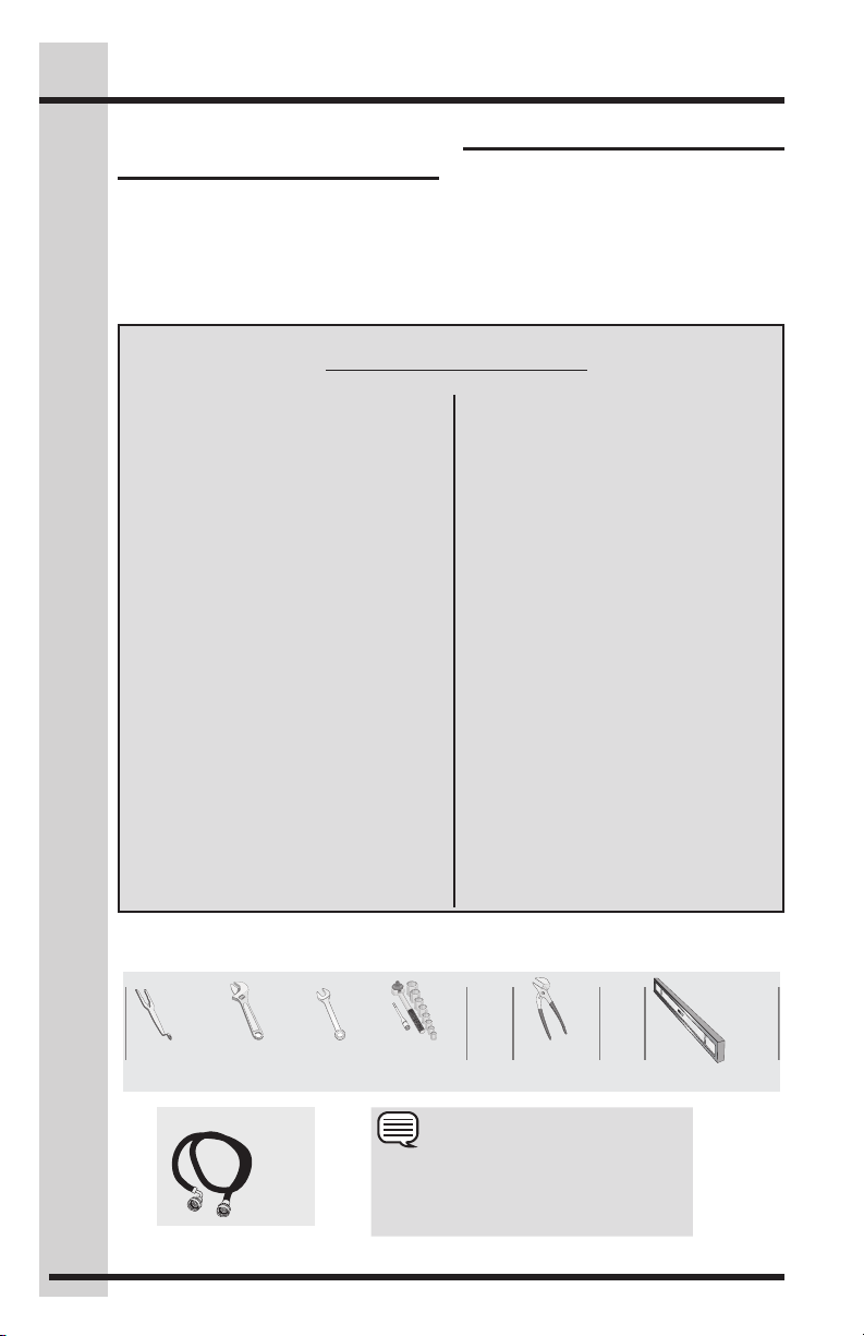
Tools and materials needed for installation:
OR OR OR AND AND
Optional
universal
Adjustable
wrench
3/8" or
10 mm
Ratchet and
socket set
NOTE
Inlet
Hose
(x2)
Hoses are not included with washer
purchase. See “Accessories” section for
various inlet hose kits to fit your specific
installation.
Adjustable
pliers
Carpenter’s level

Installation Requirements
5
Electrical system
requirements
CIRCUIT - Individual, properly polarized
and grounded 15 amp. branch circuit
fused with 15 amp. time delay fuse or
circuit breaker.
POWER SUPPLY - 2 wire, with ground,
120 volt single phase, 60 Hz, Alternating
Current.
NOTE
Because of potentially inconsistent voltage
capabilities, the use of this washer with
power created by gas powered generators,
solar powered generators, wind powered
generators or any other generator other
than the local utility company is not recommended.
OUTLET RECEPTACLE - Properly
grounded 3-prong receptacle to be
located so the power supply cord is
accessible when the washer is in an
installed position.
WARNING
Improper grounding of the washer may
cause serious injury or death. Check with a
licensed electrician if you are in doubt as to
whether the appliance is properly grounded.
Grounding type wall receptacle
Do not, under
any circumstances,
cut, remove,
or bypass the
grounding prong.
WARNING
ELECTRICAL SHOCK HAZARD
Improper connection of the equipment
grounding conductor can result in a risk
of electrical shock. Check with a licensed
electrician if you are in doubt as to whether the appliance is properly grounded.
2. Since your washer is equipped with
a power supply cord having an
equipment-grounding conductor and
a grounding plug, the plug MUST be
plugged into an appropriate, copper wired receptacle that is properly
installed and grounded in accordance
with all local codes and ordinances or
in the absence of local codes, with the
National Electrical Codes, ANSI/NFPA
70 (latest edition), or in Canada, the
Canadian electrical code C22.1 part 1.
If in doubt, call a licensed electrician.
DO NOT cut off or alter the grounding
prong on the power supply cord. In
situations where a two-slot receptacle
is present, it is the owner’s responsibility to have a licensed electrician replace
it with a properly grounded three prong
grounding type receptacle.
Water supply
requirements
Hot and cold water faucets MUST be installed within hose length of your washer’s
water inlet. The faucets MUST be 3/4 inch
(1.9 cm) with threading for laundry hose
connection. Water pressure MUST be between 20 and 120 psi. Pressure difference
between hot and cold cannot be more
than 10 psi. Your water department can
advise you of your water pressure.
Power cord with
3-prong grounded plug
Grounding requirements
1. The washer MUST be grounded. In
the event of malfunction or breakdown, grounding will reduce the risk
of electrical shock by a path of least
resistance for electrical current.
Drain system
requirements
1. Drain capable of eliminating 17 gals
(64.3 L) per minute.
2. A standpipe diameter of 1-1/4 in. (3.18
cm) minimum.
3. The standpipe height above the floor :
Minimum height: 24 in. (61 cm)
Maximum height: 96 in. (244 cm).
6
1"
(2.5 cm)
0"
(244 cm)
Installation Requirements
96"
max.
24"
(61 cm)
min.
3"
(7.6cm)
60 sq. in.
(387.1cm²)
NOTE
Drain hose length is 59 in. (150 cm). For
installations requiring a longer drain hose,
use hose P/N 137098000, available from
an authorized parts distributor.
Clearance requirements
IMPORTANT
DO NOT INSTALL YOUR WASHER:
1. In an area exposed to dripping water
or outside weather conditions.
2. In an area where gasoline or other
flammables are kept or stored. If
the washer is installed in a garage,
it must be a minimum of 18 inches
(45.7 cm) above the floor.
3. On carpet. Floor MUST be solid with
a maximum slope of 1 inch (2.5 cm).
To minimize vibration or movement,
reinforcement of the floor may be
necessary.
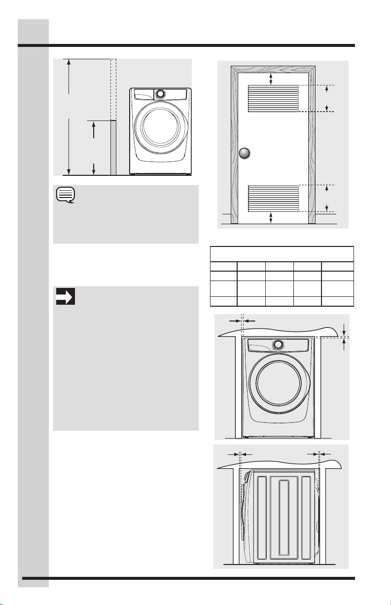
Installation in a recess or closet
If washer and dryer are installed in the
same closet, door ventilation is required:
A minimum of 120 square inches (774.2
cm²) of opening, equally divided at the
top and bottom of the door, is required.
Louvered openings should be located
3 inches (7.6 cm) from bottom and top
of door. Air openings are required to be
unobstructed when a door is installed. A
louvered door with equivalent air openings
for the full length of the door is acceptable.
60 sq. in.
(387.1cm²)
3"
(7.6cm)
closet door
MINIMUM INSTALLATION CLEARANCES -
Alcove 0” (0 cm) 0” (0 cm) 0” (0 cm) n/a
Under-
Counter
Closet 0” (0 cm) 0” (0 cm) 0” (0 cm) 1” (2.5 cm)
0"
(0 cm)
Inches (cm)
SIDES REAR TOP FRONT
0” (0 cm) 0” (0 cm) 0” (0 cm) n/a
0"
(0 cm)
(0 cm)

Installation Requirements
(135.5 cm)
Washer dimensions
(136 cm)*
53.5"
to clear open door
freestand washer
on floor
floor line
washer mounted on
optional pedestal
floor line
53.5" (136 cm)*
to clear open door
approved
stacking kit
(STACKIT7X)
required for
stacked
installation
32" (81.25 cm)*
to front of closed door
32" (81.25 cm)*
to front of closed door
water supply
connection on
rear of unit
drain hose on
rear of unit
75.75"
(192.5 cm)
water supply
connection
on rear
of unit
gas supply
pipe on rear
of gas unit
7
27.0"
(68.5 cm)
38.0"
1
(96.5 cm)
53.25"
electrical
supply on
rear of unit
centerline
height for
rear vent
3
power
3
cord
on rear
of unit
39.0"
(99 cm)
drain
hose on
rear of
unit
2
power
cord on
rear of
unit
(105 cm)
1
41.0"
floor line
*
Connection of water inlet hose on steam dryer adds 3/4 in. (2 cm) to installation depth.
1
Power supply cord length on washer approximately 60 inches (152.5 cm).
2
Drain hose length on washer approximately 59 inches (150 cm).
3
Power supply cord length on gas dryer or electric Canadian dryer approximately 60
inches (152.5 cm).

8
Unpacking Washer
Removing foam
packaging
WARNING
SUFFOCATION HAZARD
Dispose of the carton and plastic bags after
the washer is unpacked. Children might use
them for play. Cartons covered with rugs,
bedspreads, or plastic sheets can become
airtight chambers causing suffocation.
Place all materials in a garbage container
or make materials inaccessible to children.
1. Temporarily remove door tape.
2. Open washer
door and remove
everything from
the drum.
3. Close door and
reapply door
tape.
4. Using a rug,
blanket or piece
of cardboard to
protect the floor,
carefully lay the
washer on its
back.
6. Carefully
return the
washer to
an upright
position.
7. Carefully move the washer to within 4
feet (1 m) of its final location.
WARNING
ELECTRIC SHOCK HAZARD
Certain internal parts are intentionally
not grounded and may present a risk of
electrical shock if contacted during installation.
Do not contact the following parts while
the appliance is energized
• Pump
• Drive motor
• Electrical control boards
• Water valves
IMPORTANT
Save styrofoam base and shipping plug
for use to help prevent washer damage
during any future moves.
IMPORTANT
DO NOT place the washer onto its back
without the shipping bolts.
CAUTION
EXCESSIVE WEIGHT HAZARD
To avoid back or other injury, have more
than one person move or lift the washer.
5. Remove styrofoam base and shipping
plug and set them aside.
IMPORTANT
DO NOT tip washer upside down onto its
top or onto its right side for any reason.

Unpacking Washer
Removing shipping hardware
IMPORTANT
Failure to remove shipping hardware completely could result in damage to the appliance, damage to your home, or unexpected washing results.
Save all shipping bolts and spacers for future use. If the washer is to be transported at a
later date, the shipping hardware must be reinstalled to help prevent shipping damage
COLD Water Hose
HOT Water Hose
FRIA
CALIENTE
FROIDE
CHAUDE
P Clamps
Shipping Fork
(on select models)
Black Spacers
White Spacer
(on select models)
Shims
Bolts
9
For 300 Series:
Remove all of the following:
4 BOLTS
4 SHIMS
4 BLACK SPACERS
3 P CLAMPS
For 400, 500, and 600 Series:
Remove all of the following:
5 BOLTS
5 SHIMS
4 BLACK SPACERS
4 P CLAMPS
1 WHITE SPACER
1 SHIPPING FORK
NOTE
Rubber expansion material on spacers may need time to relax before they can be easily
pulled through shipping hole.
COLD Water Hose
HOT Water Hose
FRIA
CALIENTE
FROIDE
CHAUDE
x7
Installing hole plugs
Locate hole plugs in the small bag supplied with washer instruction guides. Insert
them in the holes in the washer back panel
where the shipping hardware has been
removed.

10
Installation Instructions
Leveling your washer
Excessive noise and vibration can be prevented by properly leveling the washer.
1. For free
standing
installation
and with the
washer within
4 feet (1 m) of
its final location, place a level on top of the washer.
2. Use the universal wrench to adjust the
leveling legs so
the washer is
level front-torear and sideto-side, and
stable cornerto-corner.
3. Press down
on alternate
corners and
sides and feel for the slightest movement. Adjust the appropriate leg(s) so
the washer sits
solidly on the floor
on ALL four legs.
Keep the leveling
leg extension at a
minimum for best
performance of
the washer.
raise
lower
NOTE
For pedestal installations, see additional
installation instructions included with the
pedestal.
Connecting inlet water
1. Run some water
from the hot and cold
faucets to flush the
water lines and remove
particles that might
clog the water valve
screens and to determine which faucet is
hot and which is cold
supply.
2. Check to ensure
that the inlet
hoses have the
rubber washer
firmly in place.
Rubber Washers
Must Be Present
Hoses are not included with washer
purchase. See “Accessories” section for
various inlet hose kits to fit your specific
installation.
3. Connect the HOT
inlet hose to the
HOT inlet connection on the
washer and the
COLD inlet hose
to the COLD
inlet connection
on the washer.
The cold water inlet will have a blue cap
cover on the inlet connection and the
hot water inlet will have a red cap cover
on the inlet connection. Additionally,
depending on the model, the hot and
cold inlet connections will be marked
with either an adhesive label or markings
directly on the unit to indicate which side
is cold and which side is hot.
Tighten by hand
until snug. Then
tighten each supply connection
another 2/3 turn
with pliers.
Do not cross thread or overtighten these connections.
4. Connect the HOT
inlet hose to the
HOT water supply
and the COLD inlet
hose to the COLD
water supply.
USE ONLY
NEW HOSES
NOTE
Cold Hot
Cold inlet shown
on left side (select
models only)
IMPORTANT

Installation Instructions
11
5. Tighten by hand
until snug. Then
tighten each
supply connection another 2/3
turn with pliers.
Do not bend, kink or pinch water
inlet hoses.
6. Turn on the water
and check for
leaks.
Connecting drain and
electrical
1. Verify the
anti-siphon
disc is
in place.
2. Form a “U”
shape on
the end of
the drain
hose with
the hose pointed toward the drain.
Place the formed end in a laundry tub
or a standpipe and secure the drain
hose with the cable tie (provided in the
enclosure package) to the standpipe,
inlet hose, laundry tub, etc. so the hose
does not pull out from the force of the
water.
Cable Tie
Anti-Siphon Disc
Insert Less
Than 8.5"
(21.5 cm)
NOTE
The standpipe inside diameter must be
1-1/4” (3.2 cm) minimum. There must be
an air gap around the drain hose in the
standpipe. A snug hose fit can cause a
siphoning action.
IMPORTANT
Check to ensure the power is off at a
circuit breaker/fuse box before plugging
the power cord into an outlet.
3. Plug the power cord into a grounded
outlet.
WARNING
ELECTRICAL SHOCK HAZARD
Improper connection of the equipment
grounding conductor can cause an electrical shock that may result in serious injury or death. Check with a licensed electrician if you are in doubt as to whether the
appliance is properly grounded.
See
Electrical System Requirements
Grounding Requirements
instruction for additional information.
4. Turn on the power at a circuit breaker/
fuse box.
5. Carefully slide the washer to its final
position. Recheck for level and rock
corners for stability. See “Leveling
your washer” section. Remove and
discard door tape.
6. Read the Use & Care Guide provided
with the washer. It contains valuable
and helpful information that will save
you time and money.
7. Run the washer through a complete
cycle, checking for water leaks and
proper operation.
8. If you have any questions during initial
operation, please review the “Service
Prevention Checklist” in your Use &
Care Guide before calling for service.
9. Place these instructions in a location
near the washer for future reference.
sections of this
and
NOTE
A wiring diagram and technical data
sheet are located under the washer top
panel, on top of the detergent dispenser
housing.
12
Reversing Door
NOTE
Door reversibility is available only on 500, or 600 series models.
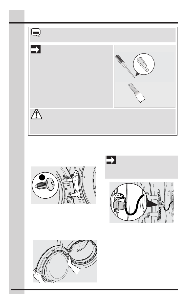
IMPORTANT
BEFORE YOU REVERSE WASHER DOOR:
1. Be sure you have adequate swing area
before reversing door.
2. Gather your tools - including a screw driver
with a #2 square bit and plastic knife (or small,
flat prying tool that won’t damage paint).
3. Protect flat work surface, such as top of
washer or floor near washer, with a soft
cloth or towel.
4. Be sure washer is unplugged from power
source!
Tools needed for reversal:
Plastic knife
Screwdriver
with #2
square bit
WARNING
Failure to disconnect power source before servicing could result in personal injury or
even death.
Removing Door Assembly
1. Completely open the door to expose all
four hinge screws.
2. Remove all four hinge screws with #2
square bit driver. Save for reinstalling later.
x4
ELECTRICAL SHOCK HAZARD
4. While supporting the door with one
hand, pinch the tabs to release the plastic terminal cap from the hinge plate.
IMPORTANT
Take care not to pull the door away from
the washer until you remove the wiring
harness terminal cap.
Fine Thread
3. Hold the door with one hand supporting the handle area and one hand
supporting the hinge. While supporting
the door at the hinge, press firmly with
the other hand until the locating pins
on the back of the hinge plate dislocate
from the front panel.
5. Set the door face down on a flat surface protected by soft cloth or towel.

Reversing Door
2
2
1
1
13
Removing Door Assembly, continued
6. Release wiring harness from retainer
on plastic terminal cap. Then release
terminal from terminal cap. Save the
cap to reinstall later.
Removing Door Lock and Plastic Hole Cover
1. Locate and remove both screws from
door lock. Save screws for later.
2. Rotate the lock as you pull it out
through the front panel. Take care not
to pull too hard or too far as the lock is
still attached to the wiring harness.
Front
x2
Coarse
Thread
3. Disconnect the wiring harness terminal
from the door lock. Set the door lock
aside for reinstallation later.
4. Pry the bottom of the plastic hole cover
upward to release it from the front
panel. You may have to use a nonscratching plastic knife if you are unable to release it manually. Then, slide
the cover down slightly and remove it
from the front panel.
Panel
Reinstalling Door Lock and Hole
Cover
1. Move the plastic cover to the other side
of the front panel. Position the cover so
the “hook” is at the bottom. Insert hook
into lower slot, slide the cover down,
and press upper retention tabs into
opening until they snap into place.
2. Insert wiring harness into door lock.
3. Insert door lock into front panel and
reinstall door lock screws.
1
2
Coarse
Thread
2
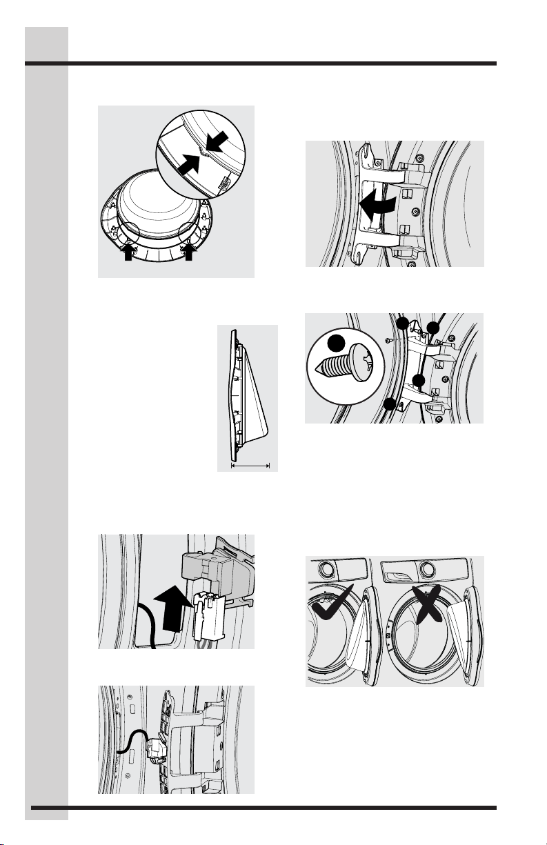
Reversing Door Assembly
1. Locate nine screws on inner door ring.
Remove each and save for reinstallation later. Remove inner door (with
hinge) and carefully set aside.
2. Lift door glass slightly and rotate 180
degrees, setting it back onto outer door.
1
180
14
Reversing Door
Reversing Door Assembly, continued
3. Make sure the alignment tabs reengage.
Connect to Notches
4. Reattach the inner door to the outer
door using the nine screws removed
earlier. See illustration, Step 1.
5. Check to verify that the
scoop (wider section) of
the door glass is situated
at the BOTTOM of the
door.
Reinstalling Door Assembly
1. Insert the wiring harness terminal into
the terminal cap and wrap the harness
into the harness retainer.
3. Insert hinge locating pins into the hole
that were previously covered by the
plastic hole cover. Press on the face
of the hinge to snap the other locating
pins into place.
4. Reinstall all four screws removed
earlier - two front screws first, then two
side screws.
1
3
x4
Fine Thread
4
2
Verify Reversed Door Operation
1. Test door for free, smooth swinging
operation and secure latching when
closed.
2. Verify inner door glass is in the correct
orientation with the “scoop” at the
bottom.
2. Slide terminal cap onto back of hinge
plate until tabs snap into place.
3. Plug in washer and close the door.
Test correct door lock operation by
starting a test cycle: lock should
engage, and door should not be able
to be opened until cycle is paused or
canceled.
Options
(67 cm)
15
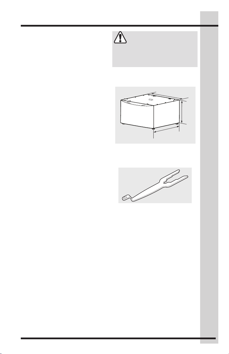
Accessories
MATCHING STORAGE PEDESTAL*
White Pedestal - P/N EPWD257UIW
Titanium Pedestal - P/N EPWD257UTT
A storage pedestal accessory, specifi-
cally designed for this washer may be
used to elevate the washer for ease of
use. This pedestal will add about 15”
(38 cm) to the height of your unit.
*Other colors may be available. Contact the
source where you purchased your washer.
DRYER STACKING KIT
P/N STACKIT7X
Depending on the model purchased, a
kit for stacking a matching dryer on top
of this washer may have been included
in the initial purchase of your dryer. If
your model did not include a stacking
kit or you desire another stacking kit,
you may order one.
INLET HOSE KITS
Please call 866-233-8353 (in Canada,
800-265-8352) to explore hose kit options that will meet your specific installation needs.
DRAIN HOSE EXTENSION KIT
P/N 137098000
In order to reach standpipe heights
or distances beyond the reach of the
drain hose supplied, order the Drain
Hose Extension Kit.
UNIVERSAL APPLIANCE WRENCH
P/N 137019200
A Universal Appliance Wrench is avail-
able to aid in dryer/washer/pedestal
feet adjustment.
TOUCH UP PAINT PENS*
White - P/N 5304468812
Titanium - P/N 5304475700
*Other colors may be available. Contact the
source where you purchased your washer.
CAUTION
Failure to use accessories manufactured
by (or approved by) the manufacturer
could result in personal injury, property
damage or damage to the washer.
27”
(68.5 cm)
15”
(38 cm)
26.5”
Storage Pedestal
Universal Appliance Wrench
Replacement parts in
U.S. and Canada:
If replacements parts are needed for
your dryer, you can contact the source
where you purchased your dryer, call
1-877-4ELECTROLUX (1-877-435-
3287) in the U.S. or 1-800-265-8352
in Canada, or visit our website,
www.electroluxappliances.com in the U.S.
or www.electroluxappliances.ca in Canada
for the Electrolux Authorized Parts Distributor nearest you.

electrolux.com/shop

EN FRONT LOAD WASHER
FR LAVEUSE À CHARGEMENT FRONTAL
ES LAVADORA DE CARGA FRONTAL
INSTALLATION INSTRUCTIONS
INSTRUCTIONS D’INSTALLATION
INSTRUCCIONES DE INSTALACIÓN
A11200201 Janvier 2018
 Loading...