

Page 1
PROline
GAS COOKER
EFG 502
Page 2

2
Page 3
CONTENTS
Instructions for the user Instructions for the installer
Important Safety Information
Description of the appliance
Technical Features
Using the appliance
- Before using the cooker for the
first time
- Using the oven
- Hints & Tips
- Cooking with the grill
- Using the Hob
Maintenance and Cleaning
Before you call for Service
How to read the instruction book
The symbols below will guide you when reading the
4
Safety Advice
5
Technical Data
6
Installation
7
7
7
Gas connections
8
9
Conversion to LP gas
10
12
14
instruction book
- Positioning
- Ventilation
- Location
- Fitting the adjustable feet
15
15
16
16
16
16
16
17
17
Safety instructions
Step by Step Operation
Advice and recommendations
Environmental Information
3
Page 4
IMPORTANT SAFETY INFORMATION
You MUST read these warnings carefully before installing or using the appliance.
Installation
• This cooker must be installed by qualified
personnel, according to the manufacturer’s
instructions and to the relevant British
Standards.
• This cooker is heavy. Take care when
moving it.
• Any gas installation must be carried out by a
registered CORGI installer.
• Remove all packaging before using the
cooker.
• Ensure that the gas and electrical supply
complies with the type stated on the rating
plate, located near the gas supply pipe.
• Do not attempt to modify the cooker in any
way.
Child Safety
• This cooker is designed to be operated by
adults. Do not allow children to play near or
with the cooker.
• The cooker gets hot when it is in use.
Children should be kept away until it has
cooled.
• Children can also injure themselves by
pulling pans or pots off the cooker.
During Use
• Ensure the control knobs are in the ‘OFF’
position when not in use.
• When using other electrical appliances,
ensure the cable does not come into contact
with the hot surfaces of the cooker.
• Unstable or misshapen pans should not be
used on the hob burners as unstable pans
can cause an accident by tipping or spillage.
• Never leave the cooker unattended when
cooking with oil and fats.
• This cooker should be kept clean at all times.
A build-up of fats or foodstuffs could result in
a fire.
• Never use plastic dishes in the oven or on
the hob burners. Never line any part of the
oven with aluminium foil.
• Always ensure that the oven vent, which is
located at the centre back of the hob, is left
unobstructed to ensure ventilation of the
oven cavity.
• Perishable food, plastic items and aerosols
may be affected by heat and should not be
stored above the cooker.
Service
• This cooker should only be repaired or
serviced by an authorised Service Engineer
and only genuine approved spare parts
should be used.
• This cooker is intended for domestic cooking
only. It is not designed for commercial or
industrial purposes.
• When in use a gas cooker will produce heat
and moisture in the room in which it has been
installed. Ensure there is a continuous air
supply, keeping air vents in good condition or
installing a cooker hood with a venting hose.
• When using the cooker for a long period
time, the ventilation should be improved, by
opening a window or increasing the extractor
speed.
• Do not use this cooker if it is in contact with
water. Do not operate the cooker with wet
hands.
• The grill pan will become hot during use,
always use oven gloves when removing or
replacing a hot grill pan.
Environmental Information
• After installation, please dispose of the
packaging with due regard to safety and the
environment.
• When disposing of an old appliance, make it
unusable, by cutting off the cable.
Keep this instruction book for future
reference and ensure it is passed on to any
new owner.
4
Page 5
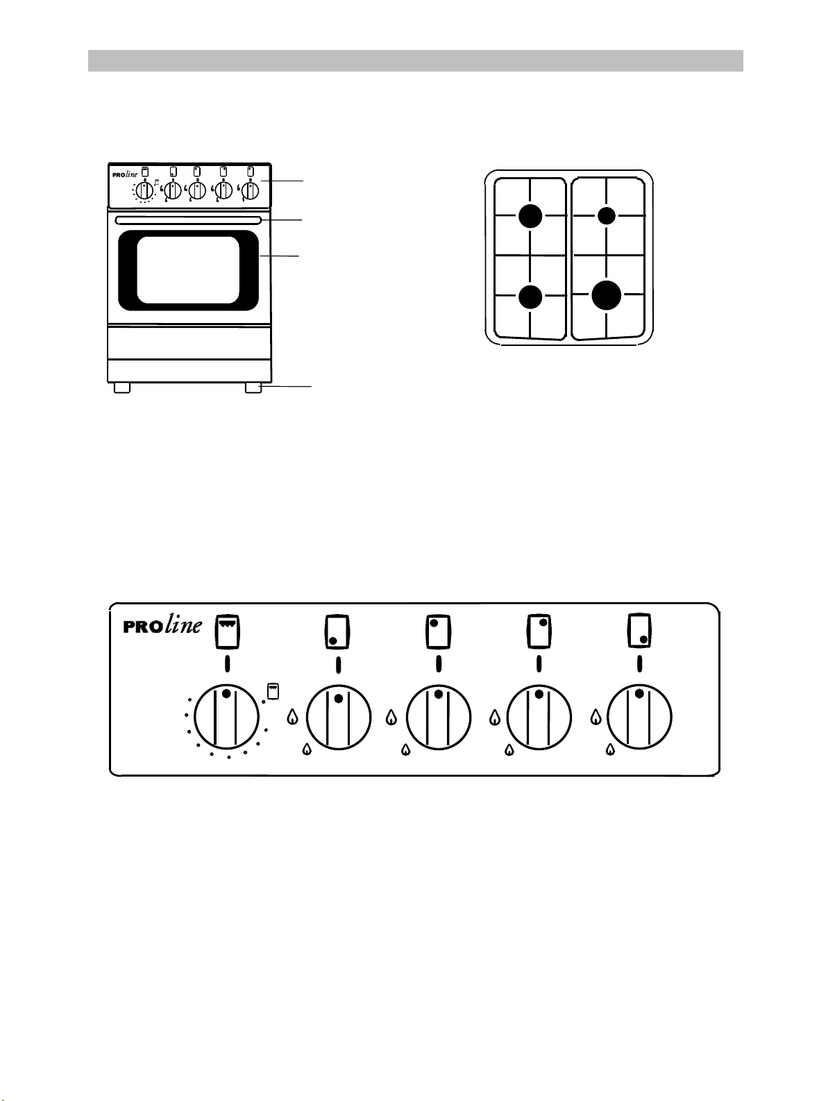
DESCRIPTION OF THE APPLIANCE
y
K
K
Hob
155
170
300
190
285
210
270
230
250
Control panel
Control panel
Door handle
Oven door
glass
Adjustable
feet
Model : EFG 502
2000W
semi-rapid
1000W
auxiliar
2
1
semi-rapid
2000W
1. Front left burner (semi-rapid)
2. Back left burner (semi-rapid)
3. Back right burner (auxiliary)
4. Front right burner (rapid)
rapid
2600W
3
4
150
162
225
237
250
FRONT
LEFT
BURNER
CONTROL
KNOB
BAC
LEFT
BURNER
CONTROL
KNOB
BAC
RIGHT
BURNER
CONTROL
KNOB
EFG 502
FRONT
RIGHT
BURNER
CONTROL
KNOB
175
187
200
212
OVEN
THERMOSTAT/
GRILL
CONTROL
KNOB
5
Page 6
TECHNICAL FEATURES
Free standing Class 1
Hob Pan support
Front right burner
Back right burner
Front left burner
Back left burner
Oven
Accessories
Dimensions
This appliance complies with the following
EEC Directives :
90/396 (Gas Appliance Directive)
93/68 (General Directives) and subsequent
modifications.
Oven power
Grill power
Oven shelf
Grill pan
Heat deflection shield
Height to the hob
Width
Depth
Enamelled
Rapid
Auxiliary
Semi rapid
Semi rapid
3,20 kW
2,50 kW
Chromed
Enamelled
Enamelled
880 - 890 mm
500 mm
600 mm
2,60 kW
1,00 kW
2,00 kW
2,00 kW
6
Page 7
USING THE APPLIANCE
Before using the cooker for the first time
Remove all packaging both inside and
outside of the cooker, before using it.
Before using for the first time, the oven should be
heated without food. During this time, an
unpleasant odour may be emitted. This is quite
normal.
1. Remove the oven accessories and ensure all
packaging has been removed.
2. Ignite the oven burner (see instructions) and
turn the control knob to 250 degrees C .
3. Open a window for ventilation.
4. Allow the oven to run empty for
approximately 45 minutes.
This procedure should be repeated with the grill
function for approximately 5-10 minutes.
Using the Oven
The cooker gets hot when it is in use.
Children should be kept away until it
has cooled.
Attention: when turning on the oven and
grill burner the oven door has to be
opened.
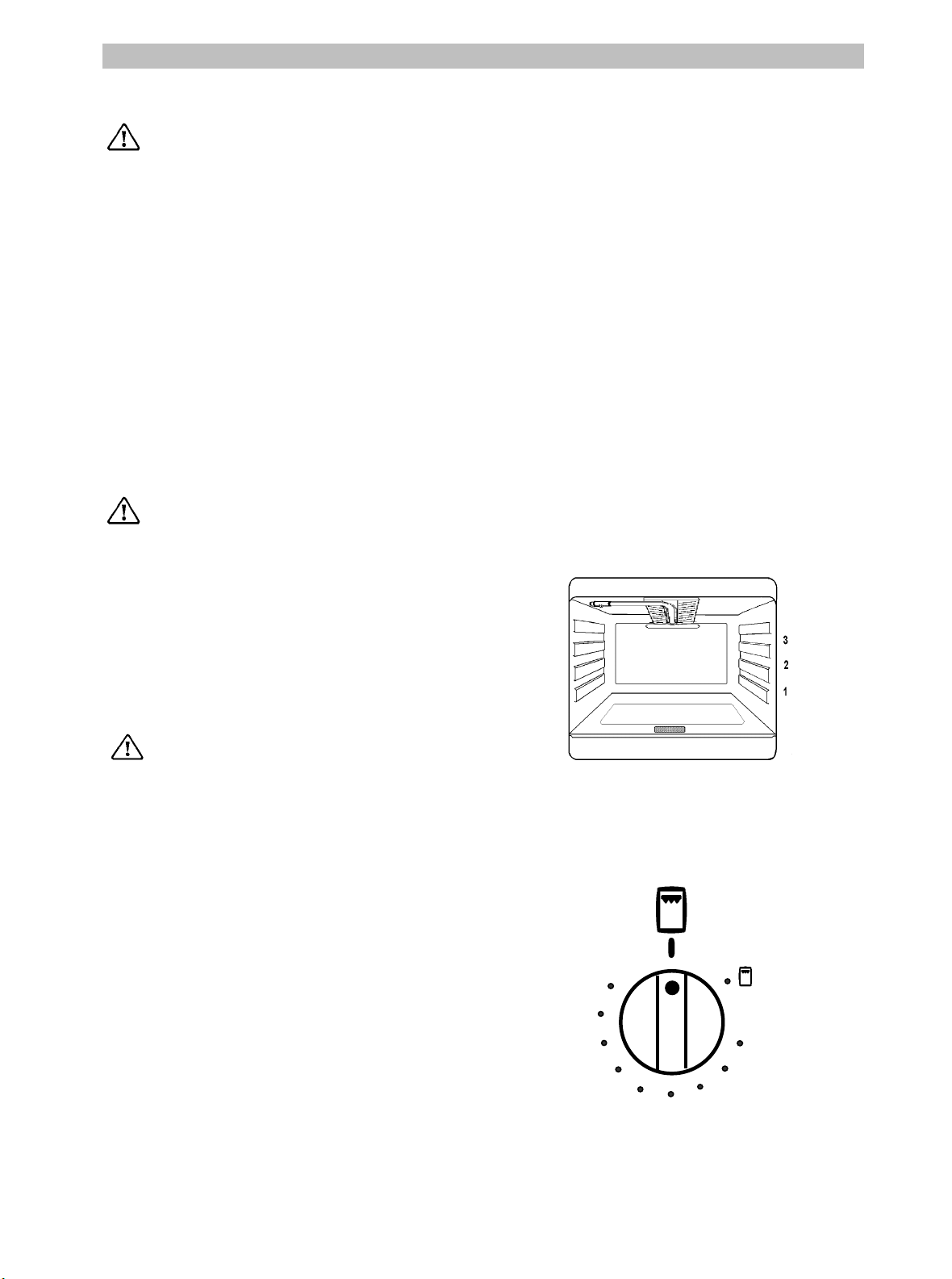
The oven has three shelf levels, and is supplied
with one shelf.
The shelf positions are counted from the bottom
of the oven as shown in the diagram.
Do not place cookware or foil directly
on the oven base.
Oven Safety device
The cooker features a thermocouple; if for
any reason the flame should extinguish, the
device will stop the gas flow.
Use
The oven can be used for traditional cooking, or
for grilling, but not both functions simultaneously.
By turning the oven thermostat control knob
anticlockwise different heat settings can be
selected between 150 - 250 degrees C for the
oven.
To select the grill function turn the oven
thermostat control knob fully anticlockwise to the
grill symbol.
150
162
175
187
200
212
250
237
225
7
Page 8

Ignition
Attention: when turning on the oven and
grill burner the oven door has to be
opened.
• Open the oven door and lift the small flap on
the bottom of the oven cavity.
• Hold a lit match or taper to the oven burner.
• Push and turn the oven thermostat control
knob in a anticlockwise direction to the
maximum position 250 degrees C.
• Hold in the knob for approximately 15
seconds to allow the flame failure device to
energise.
• Release the control knob, check that the
burner has ignited correctly.
• Close the flap and the oven door.
If for any reason the flame should extinguish turn
the control knob to the off position.
After a least 1 minute try to re-ignite the oven
following the procedure as above.
Cooking in the Oven
Traditional cooking is made by natural
convection; the heated air circulates on the
principle of ascending and descending draughts.
It is necessary to pre-heat the oven.
162
175
150
187
200
212
250
237
225
All cookers vary and it is important to be
aware of the approximate cooking
temperatures before you use the cooker.
It may be necessary to adjust the temperature to
suit your individual requirements. Only
experience will enable you to determine the
correct setting for your personal requirements.
Hints and Tips
Condensation and steam
When food is heated it produces steam in the
same way as a boiling kettle. The oven vents allow
some of this steam to escape. However, always
stand back from the oven when opening the
oven door to allow any build up of steam or heat
to release.
If the steam comes into contact with a cool surface
on the outside of the oven, e.g. a trim, it will
condense and produce water droplets. This is quite
normal and is not a fault with the oven.
To prevent discolouration, regularly wipe away
condensation and also soilage from surfaces.
Cookware
Use any ovenproof cookware, which will withstand
temperatures of 250
degrees C.
Oven dishes, etc. should not be placed directly
on the oven base.
8
Page 9

Cooking with the grill
A
Whenever the grill is in use the heat
deflection shield must be fitted to prevent
the overheating of the control knobs and
facia panel.
• First of all fit the heat deflection shield "A"
• Hold a lighted match or taper to the grill
burner.
• Push and turn the oven thermostat control
knob in a clockwise direction to the grill
symbol.
• Hold in the knob for approximately 15
seconds to allow the flame failure device to
energise.
• Release the control knob, check that the
burner has ignited correctly.
• If for any reason the flame should extinguish
turn the control knob to the off position.
• After a least 1 minute try to re-ignite the grill
following the procedure as above.
• The oven door must be left halfway open
when cooking with the grill.
150
162
You may find it useful to put a small amount of
water into the oven tray, the water will help to
prevent the fat splashing and keep the food
moist while cooking.
Accessible parts may become hot when
the grill is in us. Children should be kept
away.
The grill pan will become hot during
use, always use oven gloves when removing
or replacing a hot grill pan.
When grilling, only the top burner is heating. It is
not necessary to preheat the grill.
Safety
In the interest of safety, remember that the heat
deflection shield and accessible parts become
extremely hot when the grill is in use and will
stay hot for some time after the grill has been
turned off.
Avoid skin contact with all hot surfaces and
always keep children away from the cooker
when the grill or oven is in use.
162
150
175
187
200
175
212
187
225
200
237
250
212
250
237
225
Always use oven gloves when handling the oven
tray and oven shelf as they will become very hot
when in use.
In the interest of safety do not leave the grill
unattended when in use as the high
temperatures can quickly cause the food to burn
and could lead to a grill fire.
9
Page 10

Using the Hob
The Hob Burners
The symbol on the knob corresponds to a symbol
on the control panel (See description of appliance).
Off
Maximum level
Minimum level
Use the maximum position for boiling and the
minimum for simmering.
Always choose positions between the minimum
and maximum, never between maximum and off.
Ignition of the burners
• Push the corresponding control knob in
completely and turn it anti-clockwise to the
“large flame” symbol and ignite with a match.
• Release the control knob and ensure that the
burner has ignited. Upon ignition, adjust the
flame as required.
• If for any reason the flame should extinguish
turn off the relevant control knob, leave for at
least one minute and then re-ignite.
Extinguishing of burners
Turn thecontrol knob clockwise to the off positon
«
».
Safety
The hotplate has been designed to be as safe as
possible in use. Keep all pan handles turned to a
safe position so that they are out of reach of
children and they can not be accidentally
knocked as you walk past.
Safety Recommendations for Deep Fat Frying
Use a deep pan.
Never fill the pan more than one third full.
Do not overload the pan by trying to fry too much
food at one time.
The pan should never be more than two thirds
full with food and fat or oil.
Dry food thoroughly on kitchen paper before
frying and always lower the food slowly into the
fat or oil.
Keep the outside of the pan clean and free from
streaks of fat or oilt.
Never leave fat or oil unattended during the
heating or cooking period.
Do not put anything on the hob that is
liable to melt.
10
Page 11

Selecting the Correct burner
Above every control knob there is a symbol for the
corresponding burner.
For good cooking results, always choose pans,
which correctly fit to the diameter of the burner
used (see figs). Choose thick, flat bottom pans.
We recommend the flame is lowered as soon as the
liquid starts boiling.
The following diameter pans can be used:
Correct
Incorrect
Burner
Rapid 2,60 165 260
Semi-Rapid 2,00 140 220
Auxiliary 1,00 120 160
Power Diameter (mm)
(kW) min. max.
Accessories delivered with the
appliance
The following accessories are supplied with your
appliance.
- 1 Oven shelf
- 1 Oven tray
1 Heat deflection shield
-
In addition to the accessories supplied we
recommend you only use heatproof dishes/pans
(according to the instructions of the manufacturer).
11
Page 12

MAINTENANCE AND CLEANING
The oven should be kept clean at all
times. A build-up of fats or other
foodstuffs could result in a fire,
especially in the grill pan.
Before cleaning, ensure all control
knobs are in the OFF position, and the
appliance has cooled completely.
Cleaning materials
Before using any cleaning materials on your
oven, check that they are suitable and that their
use is recommended by the manufacturer.
Cleaners that contain bleach should
NOT be used as they may dull the
surface finishes. Harsh abrasives
should also be avoided.
External cleaning
Regularly wipe over the control panel, oven door
and door seal using a soft cloth well wrung out in
warm water to which a little washing up liquid
has been added.
locking parts
To prevent damaging or weakening the
door glass panels avoid the use of the
following:
• Household detergent and bleaches
• Impregnated pads unsuitable for non
stick saucepans
• Brillo/Ajax pads or steel wool pads
• Chemical oven pads or aerosols
• Rust removers
• Bath/Sink stain removers
Oven Door
- The door can be dismantled for cleaning as
follows:
- Open the door completely
- Revolv the two locking parts on the hinge
arms completely up.
- Partially close the door, to a 30
- Lift the door and pull out
The internal
removed for cleaning. For this purpose
remove the 2 fixing screws.
and inner door glass using warm soapy
water.
Always support the door while removing the
glass panel as the door may spring closed due
to its lighter weight.
oven door glass can be
o
angle
Clean the outer
DO NOT clean the oven door while the
glass panels are warm. If this
precaution is not observed the glass
panel may shatter.
If the door glass panel becomes
chipped or has deep scratches, the
glass will be weakened and must be
replaced to prevent the possibility of
the panel shattering.
Contact your local Service Centre who
will be pleased to advise further.
IMPORTANT: The inner door glass must be in
place when using the oven.
12
Page 13

Oven Cavity
The enameled oven cavity is best cleaned whilst
the oven is still warm.
Wipe the oven with a soft cloth soaked in warm
soapy water after each use. From time to time it
will be necessary to do a more thorough
cleaning, using a proprietary oven cleaner.
Hob
After every use wipe with a soft cloth well wrung
out in warm water to which a little washing up
liquid has been added, avoiding any leakage
through the holes of the hob. Rinse and dry with
a soft cloth.
To remove more stubborn stains, wet and leave
to dissolve, do not scratch and avoid the use of
abrasive or caustic products that could damage
the enamel.
Burner cap
Burners
The burner caps and crowns can be removed
for cleaning.
Wash the burners caps and crowns using hot
soapy water, and remove marks with a mild
paste cleaner. A well-moistened soap
impregnated steel wool pad can be used with
caution, if the marks are particularly difficult to
remove.
After cleaning, be sure to wipe dry with a soft cloth.
Do's and Don't
DO treat all glass surfaces with care to avoid
Damage or breakage
DO read the user instructions carefully before
Using the cooker for the first time.
DO Allow the oven to heat for 45 minutes
Before using for the first time, in order to
expel any smell from the new oven, without
introduction of any food
DO ensure that the stability chain has been
Fitted.
DO ensure that pan handles are turned to a safe
Position.
DO use pans with lids.
DO follow the safety information given on
Deep fat frying.
DO always fit the heat deflection shield when
Grilling and remember that it does become hot
When in use and will remain hot for some time
After the grill is turned off.
DO clean your oven regularly.
DO remove any spills as soon as they occur.
DO always use oven gloves when removing food
Shelves and trays from the oven.
DO NOT allow children near the
Cooker when in use.
Burner
ring
Burner
budy
DO NOT use small pans on large burners.
DO NOT overfill pans.
DO NOT allow fat or oils to build up in the
oven trays or oven base…
DO NOT place cooking utensils
Or plates directly onto the oven base.
DO NOT grill food containing
Fat without using the grid.
DO NOT cover the grilling
grid with aluminium foil.
DO NOT use the oven trays
for roasting.
DO NOT place hot enamel parts
In water, leave them to cool first.
DO NOT allow vinegar, coffee
Milk, salted water, lemon or
tomato juice to remain in contact
With enamel parts.
DO NOT use abrasive cleaners
Or powders that will scratch the
Surface of the enamel.
DO NOT attempt to repair the cooker.
Always consult a Qualified installer or contact
Your local Comet Service Centre
13
Page 14

BEFORE YOU CALL FOR SERVICE
If the appliance is not working correctly, please carry out the following checks, before contacting your
local Comet Service Centre.
Symptoms Solutions
1. No burner ignition
2. The gas ring burns unevenly
3. The oven or grill burner will not ignite.
4. Cooking results are not satisfactory
5. The oven smokes
Check that:
• Gas supply is completely open
• The position of gas pipe is right
• The burner is not wet
• The burner cap and ring have been replaced
correctly after cleaning
Check that:
• The main jet is not blocked and the burner
ring is clean of food particles
• The burner cap and ring have been replaced
correctly after cleaning
Check that:
• The burner is in its correct place
• The burner is not wet
• The control knob has been pressed in and
held for 15 seconds upon ignition
Check that:
• The correct temperature has been selected
Check that:
• The oven does not need cleaning
• The food has not spilled over onto the base
plate
• There is no excessive fat / juice on the oven
sides
If after these checks, the appliance still does not operate correctly, contact your local Comet Service
Centre or ring 0870 5425425 to arrange for a Service Engineer to call.
14
Page 15

SAFETY ADVICE
d
d
d
d
d
INSTRUCTIONS FOR THE INSTALLER
Important
This appliance is supplied for use on
NATURAL GAS ONLY and cannot be used
for any other gas without modification.
Conversion for use on other gases must only
be undertaken by a qualified person. For
information for use on other gases contact
your local Comet Service Centre.
The cooker must be installed by a qualified
person in accordance with the gas safety
(Installation and use) (amendment)
Regulations 1990 and the relevant building
/I.E.E. regulations.
Failure to install the appliance correctly
could invalidate any manufacturers warranty
and lead to prosecution under the above
quoted regulations.
In the UK C.O.R.G.I. registered installers are
authorised to undertake the installation and
service work in compliance with the above
regulations. All Comet authorised installers
are C.O.R.G.I. registered.
- Installation of flues and ventilation for
gas appliances of rated input not
exceeding 60 kW (1
st
, 2
n
and 3
r
family
gases) – Part 2 Specification for
installation of ventilation for gas
appliances – BS 5440;
- Gas burning appliances – Part 3
Domestic cooking appliances burning
gas – BS 5386;
- Specification for installation of low
pressure gas pipe work of up to 20mm
(R1) in domestic premises (2
n
family
gas) – BS 6891;
- Pipe threads for tubes and fittings where
pressure-tight joints are made on the
threads (metric dimensions) – BS 21:
1985;
- Flexible hoses, end fittings and sockets
for gas burning appliances – BS 669;
Installation of domestic gas cooking
appliances (1
st
, 2
n
and 3
r
family gases) – BS
6172: 1990;
TECHNICAL DATA
Normal
Burner
power
(kW)
RAPID 2.60 0.72 0.42
SEMIRAPID
2.00 0.43 0.32
AUXILIARY 1.00 0.35 0.29
OVEN 3.20 1.00 0.46
GRILL 2.50 - -
Economic
power
(kW)
Bypass
(mm)
Table no.1
(Cat : II
2H3+
Gas Type
Natural Gas
Butane
Propane
Natural Gas
Butane
Propane
Natural Gas
Butane
Propane
Natural Gas
Butane
Propane
Natural Gas
Butane
Propane
)
Pressure
20 mbar
28-30mbar
37mbar
20 mbar
28-30mbar
37mbar
20 mbar
28-30mbar
37mbar
20 mbar
28-30mbar
37mbar
20 mbar
28-30mbar
37mbar
(mbar)
Nozzle
diameter
(mm)
1.12
0,86
0,86
0.96
0,71
0,71
0.70
0,50
0,50
1.30
0,88
0,88
1,15
0,80
0,80
Cons
m3/h g/h
0.248
188,8
0.191
145,2
0.093
72,6
0.305
232,4
0,238
181,5
15
Page 16

INSTALLATION
3
3
2
3
3
3
3
Positioning
Remove all the packaging and install the cooker
in a dry well, ventilated room away from curtains,
paper, alcohol, petrol etc. (See figure).
This appliance is approved to class “1” regarding
overheating of surrounding surfaces.
It is mandatory to keep 20 mm distance from the
adjacent furniture.
L.P.G. cookers or ovens MUST NOT be
installed below ground level, i.e. in a
basement, or aboard any boat, yacht or
other vessel.
The cooking appliance must be fitted
with a stability chain firmly secured to
the wall (see fig)
Ventilation
The room containing the cooker should have an
air supply in accordance with B.S. 5440: Part 2:
Current Editions.
The following requirements for ventilation must
be met.
The cooker should not be installed in a bed
sitting room with a volume of less than 20m
is installed in a room of volume less 5m
vent of effective area of 110cm
is required; if it is
installed in a room of volume between 5m
, an air vent of effective area 50cm2 is
10m
required, while if the volume exceeds 11m
, if it
an air
and
no air
vent is required. However, if the room has a door,
which opens directly to the outside, no air vent is
required even when the volume is between 5m
and 11m3.
Fitting the adjustable feet
Unpack the support brackets with the feet
attached.Place a piece of cloth/cardboard onto
your floor to protect both your floor and the
cooker.
Lay the cooker on its back, fit the support
brackets (see fig) using the bolts, washers and
nuts supplied and ensure that the nuts are tight.
lift the cooker upright onto its feet.
660 mm
20 mm
Firmly fix
chain to rear
of cooker
Pro
line
Stability
chain
150 mm
20 mm
Stability
hook
610 mm
Chain to be as
short as
practicable
If there are other fuel burning appliances in the
same room, B.S. 5440: Part. 2: Current Editions
should be consulted to determine the requisite air
vent requirements.
Location
The cooker may be located in a kitchen, a
kitchen/diner or bed sitting room but not in a
bathroom, shower room or garage.
For information regarding the fitting of flexible
supply pipes, the highest temperature at the rear
of this cooker which may come into contact with
the supply pipe is 70°C above ambient.
L.P.G. cookers or ovens MUST NOT be
installed below ground level, i.e. in a
basement, or aboard any boat, yacht or other
vessel.
16
Page 17

1
Fitting the adjustable feet
Unpack the support brackets with the feet
attached. Place a piece of cloth/cardboard onto
your floor to prtect both your floor and the cooker.
Lay the cooker on its back, fit the support
brackets (see fig) using the bolts, washers and
nuts supplied and ensure that the nuts are tight.
lift the cooker upright onto its feet.
Levelling the cooker and fitting the plinth
• Unscrew the legs as far as possible (approx.
16mm from fully screwed in).
• Place the plinth (pos.3) so that the springs
(pos.2) reach the threaded area of the legs
and the clamp of the plinth (pos.4) is in front
of the holes (pos.5) on the under side of the
structure.
• Push the plinth towards the appliance with
both hands until the springs fasten on the legs
and the clamps go into the corresponding
holes.
4
5
3
2
1
• Adjust the legs as necessary.
GAS CONNECTIONS
Note: It is recommended that the gas
connection to the cooker is installed with a
flexible tube made to BS5386.
CONVERSION TO LP GAS
Your cooker is designed to work with natural
gas, propane or butane.
To purchase a LPG conversion kit speak to the
Retail Store from where you purchased the
product.
The conversion must only be carried out by a
corgi registered engineer and when cjhanging
injectors to a different type of gas supply the
instructions on adjustment and installation on
the particular category of gas supply must be
observed. After the conversion always carry out
the gas leak test, seal any adjustment or
preadjustment parts and affix a label to the
appliance in place of the old one, relative to the
new gas adjustment.
Stick the label supplied with the
appliance (in the nozzles bag) corresponding
to the gas type utilised.
17
Page 18

Hob burners
• Remove the pan support;
• Remove the caps and the burner crowns;
• Using a No 7 socket spanner unscrew the
injectors and replace them with those
required for the type of gas in use (see table
no. 1).
Reassemble the parts following the same
procedure in reverse.
These burners do not need any primary air
regulation.
Adjustment of minimum level for the hob
burners
The burner is correctly adjusted when the flame
is stable silent and goes out without any noise.
When changing the type of gas check that the
minimum
correct
length.
Check that, turning the control knob quickly from
the maximum position to the minimum one, the
flame does not go out.
level is correct. The air admission is
when the flame is about 4 mm in
Hob burners
To adjust the minimum level:
• Light the burner
• Turn the control knob to the position of the
minimum flame;
• Remove the control knob;
• Adjust the by pass screw (situated to the
right of the tap shaft) until a regular small
flame is reached.
• For LPG screw the by pass screw in
completely.
Reassemble the parts following the same
procedure in reverse.
Check that, when turning the control knob quickly
from the maximum position to the minimum one,
the flame does not go out.
Replace the injector of the oven burner
Oven burner
To replace the gas oven injector, follow this
procedure:
• Check the table no.1 for diameter of injector;
• Remove the oven base panel;
• Loosen the nut on the oven burner rod at the
rear of the oven;
• Remove the oven burner by pushing it
backwards.
• Replace the injector by means of a No 10
socket spanner;
Reassemble the parts following the same
procedure in reverse.
18
Page 19

Grill burner
a
To replace the grill injector, follow this procedure:
• Remove the grill burner after removing the
fixing screw.
• Replace the injector by means of a No 10
socket spanner;
• Refit all parts and test.
Flame adjustment
Oven burner
The burner is correctly adjusted when the flame is
stable, silent and goes out without any noise.
Table no.2
Gas type
G20 2,5 25,5
G30 3,5 24
G31 3,5 24
Air adjusting (mm)
Oven Grill
• When the flames are too short, the injector is
whistling or the flames have the tendency to
detach from the burner, it means that there is
too much air in the burner. If there is too much
air there is a risk that the flames will extinguish.
• But, if the flames are too long, soft, lighting,
there is not enough air in the burner. These
flames discolour the bottom of pans.
• Loosen screw M which secures the air adjuster A;
• Move the air adjuster A forward or backward
until achieving the right mixture (see table no.
2);
• Tighten the securing screw M.
Grill burner
• Loosen the screw securing the Venturi.
• Move the adjusting collar left or right until
achieving the correct flame patten (see table no.
2).
• Tighten the securing screw.
Adjustment of minimum level
Oven burn
• Remove the pan support as well as the burner
caps and the burner crowns.
• Unscrew and remove the 2 hob top fixing
screws and remove the hob top.
• Light the burner to 250 degrees C and leave
the oven door closed for about 10 min.
• Turn the thermostat control knob slowly to 150
degrees C.
• Pull off the thermostat control knob to adjust
minimum flow.
• Unscrew or screw the by-pass screw (it is
above the tap shaft) until a regular small flame
is reached.
• For LPG screw the by pass screw in
completely
The flame shouldn’t extinguish when closing the
oven door.
Grill burner
The grill temperature cannot be adjusted. To obtain
a lower temperature or slower cooking time the grill
pan must be lowered away from the flame.
AFTER COMPLETION OF ANY REPAIRS,
ADJUSTMENTS OR CONVERSION THE STATUTORY
SAFETY TESTS MUST BE CARRIED OUT.
air adjustment
opening
djustment collar screw
M
A
19
Page 20

.
Page 21

documentation manual, user maintenance, brochure, user reference, pdf manual
This file has been downloaded from:
User Manual and User Guide for many equipments like mobile phones, photo cameras, monther board, monitors, software, tv, dvd, and othes..
Manual users, user manuals, user guide manual, owners manual, instruction manual, manual owner, manual owner's, manual guide,
manual operation, operating manual, user's manual, operating instructions, manual operators, manual operator, manual product,
 Loading...