

Page 1

Installation
INSTALLATION PLANNING
A qualified installer must complete the installation of this built-in appliance. Proper
installation is your responsibility.
Carefully check the location where the hood is to be installed. The hood should be
placed for convenient access. Make certain that electrical power can be provided
in the selected location.
Plan the installation so that all minimum clearances are met or exceeded.
Dimensions shown provide minimum clearances, unless otherwise noted.
Make certain that you have everything necessary to ensure a proper
installation before proceeding.
Page 2
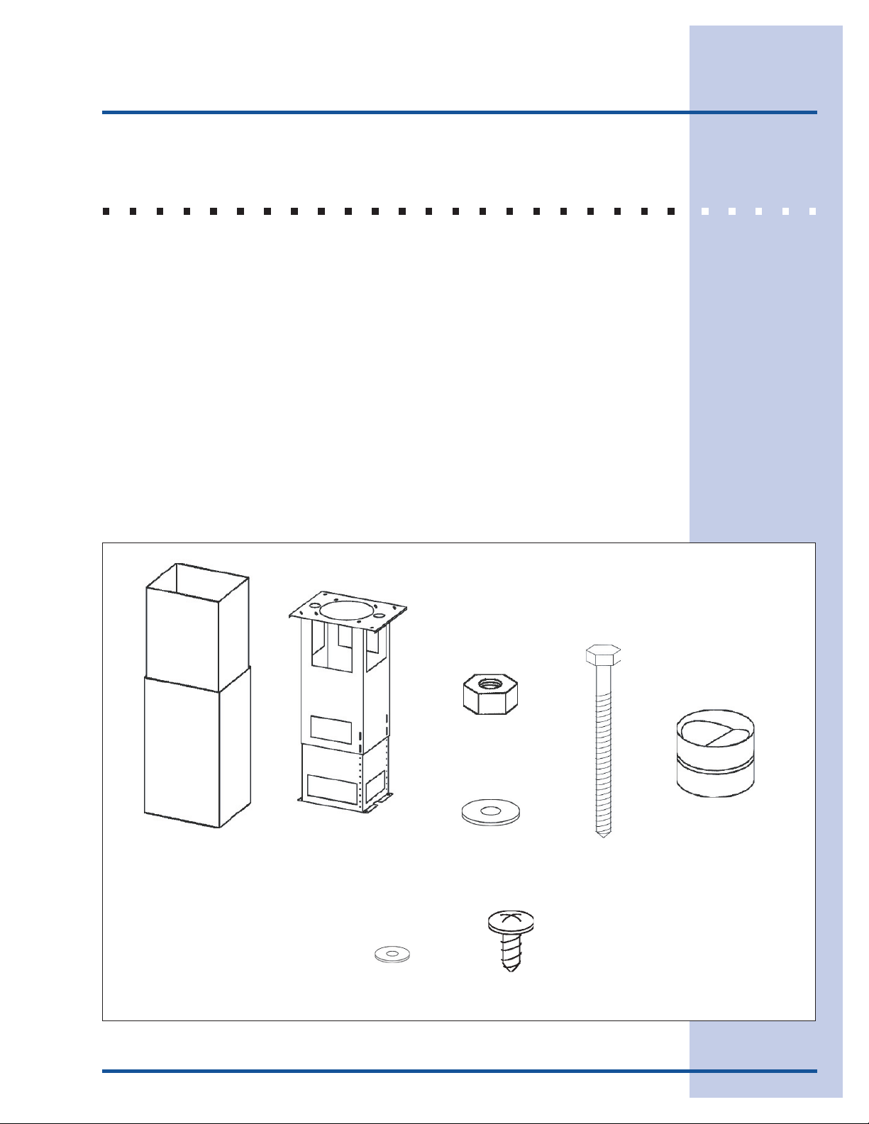
VERIFY PACKAGE CONTENTS
Unpack hood and check contents.
You should receive:
1 - Hood
1 - Decorative Flue Assembly
1 - Support Frame
1 - Duct Collar
1 - Parts Bag containing:
8 - Washers ø 6.4
4 - Washers ø 4.5
4 - Lag Bolts
8 - Mounting Screws (3.9 X 9.5mm Pan Head)
4 - Hex Nuts
1 - Installation Instructions
2 - Warranty Cards
Installation
DECORATIVE
FLUE
SUPPORT
FRAME
4 WASHERS
ø4.5
4 HEX NUTS
8 WASHERS
ø6.4
8 MOUNTING SCREWS
(3.9 x 9.5mm Pan Head)
4 Lag Bolts
(6x70mm)
DUCT COLLAR
Figure 4
Page 3
Installation
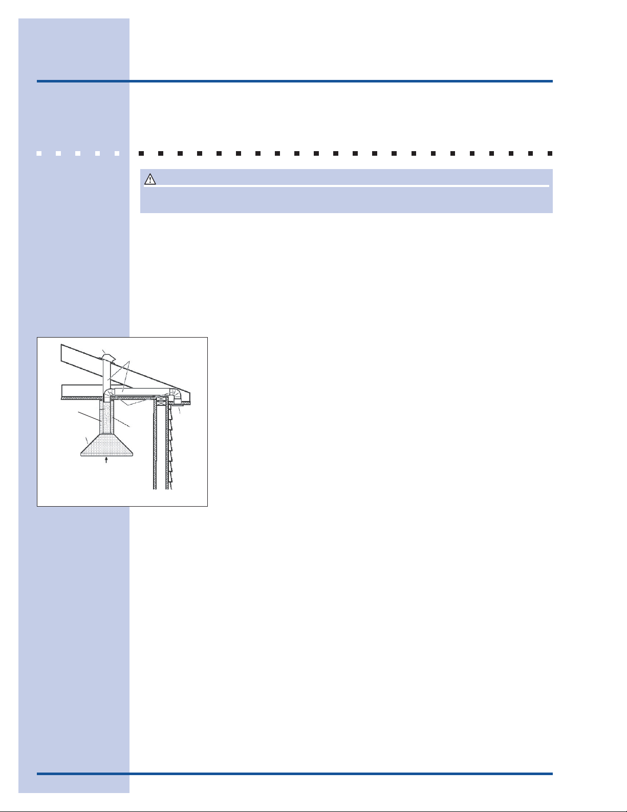
INSTALLING THE DUCTWORK
CAUTION
To reduce the risk of fire, use only metal ductwork.
1 Decide where the ductwork will run between the hood and the outside. Figure 5.
2 A straight, short duct run will allow the hood to perform most efficiently.
3 Long duct runs, elbows, and transitions will reduce the performance of the hood. Use
as few of them as possible. Larger ducting may be required for best performance
with longer duct runs.
4 Install a roof or wall cap. Connect round metal ductwork to cap and work back
towards hood location. Use duct tape to seal the joints between ductwork
sections.
ROOF CAP
DECORATIVE
FLUE
HOOD
24” to 30” ABOVE COOKING
SURFACE (See “Install Mounting
Bracket” section for mounting
restrictions).
8”
ROUND
DUCT
8”
ROUND
ELBOW
Figure 5
EAVE
VENT
Page 4

Installation
INSTALLING THE SUPPORT SYSTEM
1 At hood location, install 2 x 4 cross framing between ceiling joists
using dimensions shown in Figure 6.
2 Finish the ceiling surface. Be sure to mark the location of the
ceiling joists and cross framing.
3 Measure the ceiling height and determine distance between the cook
top and bottom of hood.
4 Per the chart, adjust overall length of the support frame as shown in
Figure 7. Remove and reinstall (4) screws in the height adjustment
slots to achieve proper length. Install (4) additional 3.9 x 9.5mm
screws and 4.5 diameter washers from the Hardware Parts Bag.
SUPPORT FRAME HEIGHT ADJUSTMENT CHART
CEILING
HEIGHT
8-FEET
9-FEET
10-FEET
(See note B)
25” 24” 23”
HOOD DISTANCE ABOVE 36” HIGH COOKTOP (SEE NOTE A)
24” 25” 26” 27” 28” 29”
SUPPORT FRAME LENGTH
46” 45” 44”
30”
31”
43”
TOP VIEW OF SUPPORT FRAME
9-13/16”
7-13/16”
Figure 6
SCREWS
9.5mm (8)
WASHERS
4.5 DIA (8)
3.9 X
NOTE
A. Minimum hood distance above the cook top must not be less than 24”.
A maximum of 30” above the cook top is highly recommended for best
capture of cooking impurities.
Distances over 30” above the cook top are at the installer’s and user’s
discretion - providing that the ceiling height and flue length permit.
B. Requires optional 10-foot flue extension model EXPV100S.
5 Secure the support frame to ceiling joists and cross framing with
(4) 6 x 70mm lag bolts and 6.4 diameter washers provided. Make
sure the bolts are driven into centers of joists and cross framing for
maximum strength. See Figure 8.
6 Run 2-wire plus ground electrical cable through the hole on top of
the support frame bracket. Cable length must extend at least 12”
below the bottom of the support frame. Secure cable to the support
frame with an appropriate cable connector.
9-13/16”
WASHER
MOUNTING
SCREWS
(6 x 70mm)
FRONT
DRYWALL
SUPPORT
FRAME
Figure 7
CROSS
FRAMING
CEILING
JOISTS
HEIGHT
ADJUSTMENT
SLOTS
Figure 8
Page 5

Installation
CONNECTING THE DECORATIVE FLUE
1 Secure the upper flue to the upper support frame with the mounting screws (3.9
x 9.5mm).
2 Insert the lower flue moving it completely towards the top and secure it temporarily
with retaining screws (3.9 x 9.5mm).
MOUNTING
SCREWS
(3.9 x 9.5mm)
UPPER
FLUE
INSERT THE LOWER FLUE
RETAINING
SCREW
(3.9 x 9.5mm)
RETAINING
SCREWS
(3.9 x 9.5mm)
TON-
LOWER
FLUE
Figure 9
Figure 10
INSTALLING THE DUCT COLLAR
1 Fold the 2 tongues outwards.
2 Secure the discharge collar to the hood with (2) retaining screws
(3.90 x 9.5mm).
DISCHAR-
GE COL-
Figure 11
Page 6

Installation
MOUNTING THE HOOD TO SUPPORT FRAME
1 Insert four (4) bolts through the top of the hood from the inside.
2 Use four (4) nuts and four (4) washers to secure hood to support frame.
INSTALLING THE ELECTRICAL
WASHER
NUT
BOLT
Figure 12
WARNING
Electrical wiring must be done by a qualified person(s) in accordance with all applicable
codes and standards. This range hood must be properly grounded. Turn off electrical power
at service entrance before wiring.
1 Remove the wiring box cover. Remove a knockout from the wiring
box.
2 Feed 6” of power cable through the knockout opening and secure
cable to the wiring box with an appropriate connector.
3 Make electrical connections. Connect white to white, black to black
and green to green.
4 Replace wiring box cover and screws. Check that wires are not
pinched between cover and box.
WIRING BOX COVER
Figure 13
Page 7

LOWER
FLUE
8” ROUND
METAL
DUCT
Installation
CONNECTING THE DUCTWORK
1 Use 8” round metal duct to connect the discharge collar on the hood to
the ductwork above.
RETAINING
SCREWS
Figure 14
MOUNTING
SCREWWS
(3.9 x 9.5 mm)
2 Use duct tape to make all joints secure and air tight.
3 Remove the two temporary retaining screws from the lower flue and set
it in place on the hood.
4 Secure decorative flue to hood with two mounting screws (3.9 x 9.5mm).
pan head mounting screws.
Figure 15
REPLACING THE BOTTOM TRIM
1 Remove the four (4) screws from the inside of the hood.
2 Remove the trim by pulling downward.
3 Slide the new trim upward into hood.
4 Replace the four screws inside hood.
Figure 16
Page 8

INSTALLING THE FILTER(S)
1 To remove the grease filter, grip the latch and pull it down. This will disengage the
filters from the hood. Tilt the filter downward and remove.
2 To install the grease filter, align rear filter tabs with slots in the hood. Pull latch
tab down, push filter up into position and release the tab. Make sure the filter is
securely engaged after installation.
NOTE
Prior to use, remove protective film from the filter frame.
GREASE
FILTERS
Figure 17
 Loading...